Universidade de Aveiro Departamento de Física, 2010
Berta Maria
Barbosa Neto
Técnicas alternativas para amplificação de Raman
em telecomunicações
“Sometimes, the reflection is far more present than the thing being reflected.”
— Jim Jarsmusch
in The Limits of Control
Universidade de Aveiro Departamento de Física, 2010
Berta Maria
Barbosa Neto
Técnicas alternativas para amplificação de Raman
em telecomunicações
Universidade de Aveiro Departamento de Física, 2010
Berta Maria
Barbosa Neto
Técnicas alternativas para amplificação de Raman
em telecomunicações
Dissertação apresentada à Universidade de Aveiro para cumprimento dos requesitos necessários à obtenção do grau de Doutor em Física, realizada sob a orientação científica de Paulo Sérgio de Brito André, Investigador auxiliar do Instituto de Telecomunicações (IT) e Professor auxiliar do Departamento de Física da Universidade de Aveiro . Apoio financeiro da FCT e do FSE no âmbito do VI Quadro Comunitário de Apoio
o júri / the jury
presidente / president Doutor João Manuel Nunes Torrão
Professor Catedrático da Universidade de Aveiro (por delegação da Reitora da Universidade de Aveiro)
vogais / examiners committee
Doutor João de Lemos Pinto
Professor Catedrático da Universidade de Aveiro
Doutor José Luís Campos de Oliveira Santos
Professor Professor Associado com Agregação da Faculdade de Ciências da Universidade do Porto
Doutor Hypolito José Kalinowsky
Professor Associado da Universidade Tecnológica Federal do Paraná, Brasil
Doutor Henrique José Almeida Silva
Professor Associado da Universidade de Coimbra
Doutor António Luís Jesus Teixeira
Professor Associado da Universidade de Aveiro
Doutor Paulo Sérgio de Brito André
Investigador auxiliar do Instituto de Telecomunicações (IT) e Professor Auxiliar da Universidade de Aveiro e (orientador)
agradecimentos O trabalho desenvolvido no âmbito desta tese contou, felizmente, com as contribuições de pessoas e instituições , pelo que quero expressar a todos os meus mais sinceros agradecimentos.
Ao Doutor Paulo André, pela atitude diligente com que orientou esta tese, nomeadamente o apoio prestado em todas as fases do trabalho, a disponibilidade para esclarecimento de dúvidas, alguma liberdade de ação que muito contribuiu para o meu desenvolvimento pessoal, e finalmente o apoio na revisão dos vários capítulos desta tese.
À Fundação para a Ciência e Tecnologia (FCT) pelo suporte específico dado a este trabalho através da bolsa (SFRH/BD/28904/2006) e pelo financiamento providenciado através dos projectos ARPA (POSC/EEA-CPS/55781/2004), TECLAR (POSI/V.5/A0072/2005) e FEFOF (PTDC/EEA-TEL/72025/2006). Ao Instituto de Telecomunicações (IT) por ter disponibilizado os recursos materiais que permitiram a realização desta dissertação. Ao National Intitute of Information and Communications Technology (NICT), Tóquio, Japão, pelo acolhimento e disponibilização de recusos labororatoriais de topo no âmbito de um estágio de curta duração, ao Doutor Hideaki Furakawa pelo acompanhamento experimental e ao Doutor Nayoa Wada pela sua atenta supervisão. Aos Doutores António Teixeira, Rogério Nogueira e Natasa Pavlovich, investigadores do IT e da Nokia Siemens Networks, pela pela interação, aprendizagem, por muitas e úteis informações que me ajudaram a perspectivar outros pontos de vista sobre o meu trabalho e pelos constantes incentivos e amizade.
Ao Mestre Claunir Pavan pela imprescindível ajuda e apoio com a edição da tese. Aos Mestres Ana Rocha, Donato Sperti, Cláudia Reis, Rogério Dionísio, Jacklyn Reis, Rui Morais, João Ferreira, Albano Baptista e Rodolfo Andrade, Engs. Pedro Teixeira, João Andrade, Andreas Klingler e José Pedro Girão, agradeço a colaboração no trabalho experimental e outras aprendizagens paralelas aos trabalhos desta tese.
Finalmente, aos meus colegas do grupo de comunicações óticas, pelo companheirismo e boa disposição com que engrandeceram o meu dia-a-dia.
Palavras Chave Redes de acesso, amplificadores de Raman em fibra ótica, otimização do ganho, redes óticas de rajadas/pacotes, efeitos transitórios
Resumo O presente trabalho centra-se no estudo dos amplificadores de
Raman em fibra ótica e suas aplicações em sistemas modernos de comunicações óticas. Abordaram-se tópicos específicos como a simulação espacial do amplificador de Raman, a equalização e alargamento do ganho, o uso de abordagens híbridas de amplificação através da associação de amplificadores de Raman em fibra ótica com amplificadores de fibra dopada com Érbio (EDFA) e os efeitos transitórios no ganho dos amplificadores. As actividades realizadas basearam-se em modelos teóricos, sendo os resultados validados experimentalmente.
De entre as contribuições mais importantes desta tese, destaca-se (i) o desenvolvimento de um simulador eficiente para amplificadores de Raman que suporta arquitecturas de bombeamento contraprogantes e bidirecionais num contexto com multiplexagem no comprimento de onda (WDM); (ii) a implementação de um algoritmo de alocação de sinais de bombeamento usando a combinação do algoritmo genético com o método de Nelder-Mead; (iii) a apreciação de soluções de amplificação híbridas por associação dos amplificadores de Raman com EDFA em cenários de redes óticas passivas, nomeadamente WDM/TDM-PON com extensão a região espectral C+L; e (iv) a avaliação e caracterização de fenómenos transitórios em amplificadores para tráfego em rajadas/pacotes óticos e consequente desenvolvimento de soluções de mitigação baseadas em técnicas de clamping ótico.
Key words Optical access networks, Raman fiber amplifiers, gain optimization, optical burst/packet switching networks, transient effect in optical amplifiers.
Abstract The present work is based on Raman Fiber Amplifiers and their
applications in modern fiber communication systems. Specific topics were approached, namely the spatial simulation of Raman fiber amplifiers, the gain enlargement and equalization the use of hybrid amplification approaches by association of Raman amplifiers with Erbium doped fiber amplifiers (EDFA) and the transient effect on optical amplifiers gain. The work is based on theoretical models, being the obtained results validated experimentally.
Among the main contributions, we remark: (i) the development of an efficient simulator for Raman fiber amplifiers that supports backward and bidirectional pumping architectures in a wavelength division multiplexing (WDM) context; (ii) the implementation of an algorithm to obtain enlargement and equalization of gain by allocation of pumps based on the association of the genetic algorithm with the Nelder-Mead method; (iii) the assessment of hybrid amplification solutions using Raman amplifiers and EDFA in the context of passive optical networks, namely WDM/TDM-PON with extension the C+L spectral bands; (iv) the assessment and characterization of transient effects on optical amplifiers with bursty/packeted traffic and the development of mitigation solutions based on optical clamping.
Contents
Contents i
List of Acronyms iii
List of Symbols vii
List of Tables ix
List of Figures xi
1 Introduction 1
1.1 Background and motivation . . . 1
1.2 Raman amplification - state of the art . . . 5
1.3 Objectives and thesis organization . . . 8
1.4 Summary of results . . . 9
1.4.1 List of publications . . . 10
References . . . 14
2 Raman amplification theory 19 2.1 Introduction . . . 19
2.2 Theory . . . 20
2.3 Single pump amplification . . . 22
2.3.1 Pump depletion . . . 27
2.4 Performance limiting factors . . . 29
2.4.1 Amplified spontaneous emission (ASE) . . . 29
2.4.2 Multipath interference . . . 33
2.4.3 Pump noise transfer . . . 34
2.5 Chapter summary . . . 34
References . . . 35
3 Modeling Raman fiber amplifiers 37 3.1 Introduction . . . 37
3.2 Mathematical model . . . 38 i
List of Figures
3.3 Numerical approaches . . . 40
3.3.1 Shooting Method . . . 40
3.3.2 Collocation Method . . . 43
3.4 Stability analysis . . . 44
3.4.1 Lyapunov second method . . . 47
3.4.2 Second equilibrium point . . . 48
3.5 Average Power Analysis . . . 49
3.6 Experimental validation . . . 52
3.7 Chapter summary . . . 54
References . . . 55
4 Gain optimization of Raman amplifiers 59 4.1 Introduction . . . 59
4.2 Multi-pump allocation . . . 61
4.3 Metaheuristics . . . 62
4.4 Hybrid Genetic Algorithm . . . 67
4.5 Simulation implementation . . . 69 4.5.1 Dimensioning of operators . . . 69 4.5.2 Dimensioning hybrid GA . . . 73 4.6 Experimental validation . . . 75 4.7 Chapter summary . . . 81 References . . . 82
5 Optical amplifiers in access networks 87 5.1 Introduction . . . 87
5.2 Transients in Raman amplifiers . . . 91
5.3 Raman amplification in hybrid WDM/TDM-PON . . . 95
5.4 Hybrid amplification schemes . . . 101
5.4.1 EDFA modeling . . . 101
5.4.2 EDFA transients . . . 106
5.4.3 EDFA transient mitigation . . . 114
5.4.4 Transmission at 10 Gb/s . . . 127
5.5 Chapter summary . . . 135
References . . . 135
6 Conclusions 143 6.1 Conclusions . . . 143
6.2 Directions for future work . . . 145
List of Acronyms
Notation Description
APA Average Power Analysis.
ASE Amplifier Spontaneous Emission. ATM Asynchronous Transfer Mode. AWG Arrayed-Waveguide Grating. BERT Bit Error Rate Tester.
BPON Broadband PON.
BVP Boundary Value Problem.
CapEx Capital Expenditures.
CO Central Office.
CW Continuous Wave.
CWDM Coarse Wavelength Division Multiplexing. DCF Dispersion Compensating Fiber.
DFB Distributed Feed-Back.
DS Down-Stream.
DSF Dispersion Shifted Fiber.
DWDM Dense Wavelength Division Multiplexing.
EDF Erbium Doped Fiber.
EDFA Erbium Doped Fiber Amplifier.
EPON Ethernet PON.
FBG Fiber Bragg Grating.
FTTH/P Fiber-to-the-Home/Premise.
FWM Four-wave Mixing.
GA Genetic Algorithm.
GPON Gigabit PON.
List of Acronyms
Notation Description
IP Internet Protocol.
IVP Initial Value Problem. MPI Multi Path interference.
MZI Mach-Zehnder Interferometer. ODE Ordinary Differential equation. OLT Optical Line Terminal.
ONU Optical Network Unit.
OpEx Operational Expenditures. OSNR Optical Signal to Noise Ratio. PON Passive Optical Network. PRBS Pseudo Random Bit Sequence. QoS Quality-of-Service.
RFA Raman Fiber Amplifier.
RN Remote Node.
SARDANA Scalable Advanced Ring-based passive Dense Access Network Architecture.
SOA Semiconductor Optical Amplifier. SRS Stimulated Raman Scattering. SSMF Standard Single Mode Fiber.
TDM-PON Time Division Multiplexing - Passive Optical Network.
US Up-Stream.
VOA Variable Optical Attenuator.
WDM Wavelength Division Multiplexing.
WDM-PON Wavelength Division Multiplexing - Passive Optical Network.
WDM/TDM-PON Wavelength Division Multiplexing/Time Division Multiplexing - Passive Optical Network.
List of Acronyms
Notation Description
YDFA Ytterbium Doped Fiber Amplifier.
List of Symbols
List of Symbols
Symbol Description
h Planck Constant.
c Speed of the light in vaccum. kB Boltzmann Constant.
PP Pump power.
Ps Data signal power.
PASE Amplified spontaneous emission power.
PSRB Single Rayleigh backscattering power.
PDRB Double Rayleigh backscattering power.
αp Fiber attenuation at the pump wavelength.
αs Fiber attenuation at the data signal wavelength.
gR Raman gain efficiency.
γR Raman gain coefficient.
TR Raman time constant.
Lef f Effective length.
Gon/of f On/off gain.
Gnet Net gain.
ns data signal number of photons.
np pump number of photons.
T Absolute temperature. η(T ) Phonon occupancy factor. N F Noise figure.
N Fef f Effective noise figure.
RIN Relative intensity noise.
V Group velocity.
J Jacobi matrix.
n Refractive index.
n2 Nonlinear refractive index.
χ(3) Third order nonlinear susceptibility.
τ Fluorescence lifetime.
D Relative inversion of population. vii
List of Symbols
Symbol Description
σ12 Absorption cross section.
σ21 Emission cross section.
S Active area.
PIS Intrinsic saturation power.
τe Characteristic decay time.
γ Saturation factor.
List of Tables
3.1 Stability properties of linear systems. . . 45 4.1 Optimized pumps wavelengths and powers. . . 70 4.2 Optimized ripples (means and standard deviations) obtained in 10 trials
at the end of the first generation for population sized with 25, 50, 75 and 100 individuals. . . 71 4.3 Optimized ripples (means and standard deviations) obtained in 10 trials
for different types of selection methods at the end of 10 generations. . . 72 4.4 Optimized ripples (means and standard deviations) obtained in 10 trials
for different types of crossover methods at the end of 10 generations. . . 72 4.5 Optimized ripples (means and standard deviations) obtained in 10 trials
for different types of mutation methods at the end of 10 generations. . . 73 5.1 Tested bit sequence. . . 93 5.2 Summary of possible scenarios of deployment of SARDANA network. . 97 5.3 Channel dropping order along the ring (2 channels per node) for
Situation A. . . 98 5.4 Channel dropping order along the ring (2 channels per node) for
Situation B. . . 98 5.5 Tested bit sequences. . . 113
List of Figures
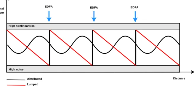
1.1 Representation of the ITU wavelength grid [4]. . . 2 1.2 Optical signal power evolution in a distributed and in a lumped
amplification scheme. . . 3 1.3 Number of citation in the IEEE database of optical amplifiers namely
RFA, EDFA and SOA from 1975 to the present. Lines are visual guides for the eyes. . . 4 2.1 Sheme describing inelastic spontaneous Raman Scattering (top) with
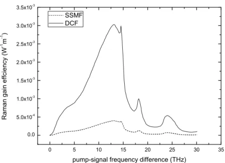
the Sokes radiation, (middle) anti-skokes radiation. (bottom) Elastic Rayleigh radiation. . . 20 2.2 Sheme describing stimulated Raman scattering. . . 21 2.3 Raman gain coefficient spectra for two germanosilicate fibers: Standard
Single Mode Fiber (SSMF) and Dispersion Compensating Fiber (DCF), for a pump wavelength of 1450 nm. . . 22 2.4 General scheme for a distributed Raman amplifier. For simplicity the
optical isolators used to protect the pumps and signals sources, were omitted. . . 23 2.5 Pump power evolution along 40 km of SSMF in the small signal
approximation and considering pump depletion for an input signal power equal to 1 mW, 10 mW and 50 mW. . . 25 2.6 Signal power evolution along 40 km of SSMF in the small signal
approximation and considering pump depletion. The initial pump power is equal to 500 mW. . . 25 2.7 Pump power evolution along 40 km of SSMF in the small signal
approximation and considering pump depletion for an input signal power equal to 1 mW, 10 mW and 50 mW. . . 26 2.8 Net gain and effective noise figure spectra for a system with two
bidirectional pumps and 25 × 400 GHz data signals along a span of 50 km SSMF. . . 31 2.9 Noise Figure spectra for temperatures equal to 300 K, 200 K, 100 K and
0 K. . . 33 xi
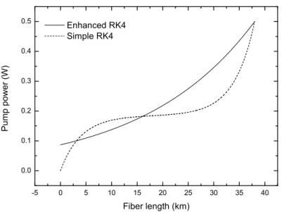
List of Figures 3.1 Pump power solutions obtained through direct shooting along the fiber
length. (solid line) - Enhanced RK4, (dashed line) - Simple RK4. . . 43 3.2 Phase portrait. . . 48 3.3 Sheme of the implemented method for one data signal and one
backward pump. . . 50 3.4 Raman gain efficiency spectrum. The points were obtained
experimentally according to [27]. . . 50 3.5 Spatial evolution of 2 counter propagated pumps, 1 co propagate pump
and 4 probe signal along a 40 km SSMF fiber span amplifier. Probe signals evolution. . . 51 3.6 Spatial evolution of 2 counter propagated pumps, 1 co propagate pump
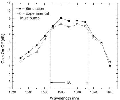
and 4 probe signal along a 40 km SSMF fiber span amplifier. Pump signals evolution. . . 52 3.7 Scheme of the experimental setup. . . 52 3.8 Measured optical spectrum for the 4-pump Raman module at 20
percent of the total power (A 3 dB attenuator was considered in this measurement). . . 53 3.9 Measured and simulated on/off gain. . . 53 4.1 Gain enlargement and equalization using multi-pump allocation. . . 61 4.2 Crossover and mutation operation scheme. . . 64 4.3 The generic evolutionay algorithm. . . 64 4.4 Scheme of the Nelder-Mead algorithm. . . 69 4.5 Scheme of the implemented setup for the 5 pumps scenario. . . 70 4.6 Optimized ripples at the end of the GA and the hybrid GA for different
number of generations for a population size of 50 individuals. The line is the exponential interpolation. . . 74 4.7 Relative Nelder-Mead time and the corresponding ripple variation. The
lines are visual guides. . . 74 4.8 The GA, the Nelder-Mead and the total simulation times for a hybrid
GA against the number of generations for a population size of 50 individuals. The lines are visual guides. . . 75 4.9 Scheme of the used experimental setup. . . 76 4.10 Gain spectrum for the single pump scheme. Only the experimental
bandwidth is assigned in the graphs. . . 77 4.11 Gain spectrum for multipump scheme. Only the experimental
bandwidth is assigned in the graphs. . . 78 4.12 Measured and simulated on/off gain for optimized pumping power. . . 79 4.13 Power evolution of optimized pumps along 20 km of SMF (lines). The
geometric shapes stand for the used experimental values. . . 80 xii
List of Figures
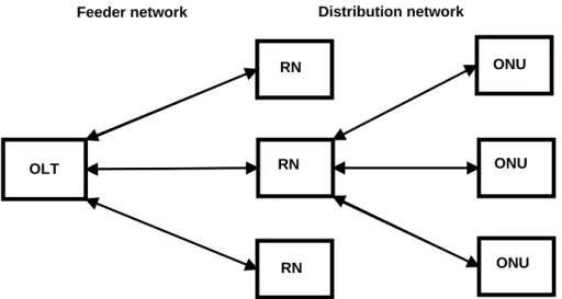
4.14 Experimental (arrows) and simulation (line) on/off spectral gain for the 20 probe signals and 7 counter propagated pumps, over 20 km of SMF fiber. . . 81 5.1 General scheme of a PON and its subnetworks: feeder and distribution. 87 5.2 Two different PON architectures: (left) TDM-PON; (rigth) WDM-PON [5]. 89 5.3 Bit sequence at the receiver: top - Raman amplification, bottom- EDFA
amplification. The vertical scale is arbitrary and the horizontal scale is 500 ns/div. . . 93 5.4 Experimental BER for the Raman and EDFA amplification, and the back
to back situation. The lines are visual guides. . . 94 5.5 Packet signals bit sequences, the time between burst is 2 µs. Packet
occupancy densities: from left to right and from top to bottom: 90, 70, 50, and 20 percent. The vertical scale is arbitrary and the horizontal scale is 500 ns/div. . . 94 5.6 Q factor as function of the packet occupancy density. The lines are
visual guides.. . . 95 5.7 SARDANA architecture scheme. . . 96 5.8 Net gain and OSNR spectra after dropping for normal scenario. Lines
are guides for the eyes. . . 99 5.9 Net gain spectrum after dropping for resilient scenario. Lines are
guides for the eyes. . . 99 5.10 OSNR spectrum after dropping for the resilient scenarios. Lines are
guides for the eyes. . . 100 5.11 Pump power value in each node. . . 100 5.12 Energy level diagram corresponding to a Stark split three level laser
system. The symbols A±N Rindicate the thermalization between adjacent Stark sub-levels, while W and A denote stimulated and spontaneous emission or absorption rates, respectively and R pump rate. . . 102 5.13 Erbium ion energy-level scheme. . . 102 5.14 Emission and absoption cross sections spectra for alumino
germanosilicate Er3+glass fibers. . . 103
5.15 Gain coefficient spectra for different relative inversion of population for an alumino-germanosilicate Er fiber. D = −1 indicates that all the ions are in the gound state, while D = +1 denotes a fully inversion of population. . . 104 5.16 Net gain spectra at the output of three EDFA with 2.5 m , 5.0 m and
7.5 m, respectively. The pump is a 1480 nm diode laser with 100 mW of power forwardly injected into the EDF. . . 106
List of Figures 5.17 216−1 bit PRBS packet - 50000 bit idle obtained in the oscilloscope at the
receiver for a Raman amplification with 40 km of SSMF. The horizontal scale is 5.000 µs/div and the vertical scale is arbitrary. . . 110 5.18 Visualized packets and their envelope exponential fit. . . 112 5.19 Packet decaying time as a function of the idle time. The line represents
an exponential fit in the form A0exp (B0) + C0. A0 = 3.32 ± 0.27 µs,
B0 = 36.39 ± 10.22 µs, C0 = 1.35 ± 0.25 µs, r2 = 0.9803. . . 113
5.20 Visualized sequences at the receiver: (a) Sequence C, (b) Sequence D. Horizontal scale 20.00 µs/div and vertical scale is arbitrary. . . 114 5.21 Visualized sequences at the receiver: (a) Sequence A, (b) Sequence B.
Horizontal scale 5.000 µs/div and vertical scale is arbitrary. . . 114 5.22 Q factor as a function of the occupancy density. The lines are visual
guides. . . 115 5.23 Scheme of the experimental setup used for the gain clamping. . . 116 5.24 Spectra captured by the OSA. Horizontal scale 0.47 nm/div, vertical
scale 10 dB/div. . . 117 5.25 Spectra captured by the OSA. Horizontal scale 0.47 nm/div, vertical
scale 10 dB/div. . . 118 5.26 (left) Packets gain excursion as a function of the re-injected signal
power. (right) System signal-to-noise ratio as a function of the re-injected signal power with traffic based on packets and PRBS of length 231− 1 and 215− 1. The receiver power is kept constant equal to -8 dBm. 119
5.27 Gain excursion as a function of the feedback signal power for packets with idle time equal to 5 µs (50000 bits), 10 µs (100000 bits) and 20 µs (200000 bits) at 10 Gb/s. The receiver power is kept constant equal to -8 dBm. . . 120 5.28 Signal-to-noise ratio as a function of the feedback signal power for
packets with idle time equal to 5 µs (50000 bits), 10 µs (100000 bits) and 20 µs (200000 bits) at 10 Gb/s. The receiver power is kept constant equal to -8 dBm. . . 121 5.29 Generic clamping scheme feasible in a WDM/TDM-PON remote node
(RN) in which two channels are dropped / added. . . 122 5.30 Packet gain excursion as function of control signal power for an EDF
with 15 m. (black squares) fForward clamping, (red circles) backward clamping. . . 123 5.31 Scheme of the implemented experimental setup. . . 123 5.32 Back-to-back. (Left)-Pattern- horizontal scale 10.00 µs/div, vertical scale
30 mV/div. (Right) eye diagram- horizontal scale 200 ps/div, vertical scale 30 mV/div. . . 124
List of Figures
5.33 Receiver output with the CW signal off. (Left)-Pattern- horizontal scale 10.00 µs/div, vertical scale 100 mV/div. (Right) eye diagram- horizontal scale 100 ps/div, vertical scale 100 mV/div. . . 124 5.34 Packet gain excursion as function of control signal power. Continuous
lines are linear fits. (squares) - Simple clamping, adjusted r square= 0.79; (circles) enhanced clamping, adjusted r square = 0.73. The dashed line stands for the gain excursion level for the unclamped situation. . . . 125 5.35 Q factor at the receiver as a function of the clamping control signal
power. (squares) - Simple clamping and (circles) enhanced clamping. The dashed line stands for the Q-factor level for unclamped situation. . 126 5.36 Scheme of the implemented experimental setup. . . 127 5.37 Optical spectrum at the output of (a) the negative dispersion fiber and
(b) the receiver. The vertical and horizontal scales are 10 dB/div and 2.00 nm/div, respectively. . . 128 5.38 Eye diagram at the receiver when all the low frequency modulated
channels are (left) off and (rigth) on. . . 129 5.39 Signal pattern, of the test signal, in the presence of add/drop function.
The vertical scales are arbitrary. . . 129 5.40 BER versus the optical power at the receiver. The squares represent the
back-to-back, circles represent all the channels on and triangle shown the situation where only channels X is on. Lines are guides for the eyes. 130 5.41 Pattern and eye diagram at the end of the: (a) Tx, (b) Rx with fiber 1 and
(c) Rx with fiber 2. . . 131 5.42 BER curves for back to back, fiber 1 and fiber as a function of the power
at receiver. . . 132 5.43 Raman gain efficiency for pumping at 1480 nm. The channels are
represented by arrows (black-C band and red-L band). The curve was obtained by interpolation of experimental data [57]. . . 133 5.44 (Top)- Net gain dropping spectrum after dropping. Squares- simple
Raman. Circles- optimized hybrid Raman/ in line EDFA. The horizontal dashed line settles a detection threshold. (Middle)-Optimized spans of EDF and their positions along the ring. The vertical dashed lines are used to place the dropped channel wavelength along the ring. The total pump power is equal to 1 W. (Bottom) - Available power to pump the EDF along the ring. . . 134
Chapter 1
Introduction
1.1
Background and motivation
The unprecedented popularity of Internet and its derived new services such as video streaming delivery (HDTV, IPTV, etc) and file sharing applications (Peer-to-Peer for example) have pressed out the competition among providers in order to reduce the cost of the transmission systems.
In the 90s, the use of optical amplifiers brought a great development in the simplification of those systems by eliminating expensive and limitative optoelectronic regeneration. Thus substantial improvements have been brougth to transmission systems in terms of cost, flexibility design and capacity. Before them, the standard method to compensate the power loss in optical fiber was to use periodically spaced electronic regenerators along the transmission link.
In those expensive devices, the signal in the optical domain was converted to the electric domain using a photodetector, being processed, amplified and then reinjected into the optical fiber by a transmitter. One advantage of this technology is that the transmission impairments such as noise, dispersion and nonlinearities do not accumulate along the link, being compensated in each node. However, system upgrades, such as bit rates and modulation formats are expensive and difficult to implement because all the regenerators of the link have to be replaced. Besides that, the huge bandwidth of the optical fiber cannot be exploited properly.
The introduction of wavelength division multiplexing (WDM) is of great importance because it enabled the implementation of the actual high capacity optical fiber networks by fully exploiting the fiber bandwidth [1]. WDM exists in several frequency patterns which differ in the spacing of the wavelengths, number of channels, and the optical amplification ability. Conventional WDM systems provide up to 16 channels in the 3rd transmission window (C-Band) of Silica fibers around
1550 nm, while dense wavelength division multiplexing (DWDM) uses the same transmission window but with denser channel spacing. Channel plans vary, but a typical system would use 40 channels at 100 GHz spacing or 80 channels with 50 GHz spacing. Some technologies are capable of 25 GHz spacing (sometimes called ultra dense WDM). These solutions are extensively used in long haul systems, sending as much information as possible. New amplification options (Raman amplification)
1. Introduction
enable the extension of the usable wavelengths to the L-band by doubling these numbers [2]. Coarse wavelength division multiplexing (CWDM) uses increased channel spacing to reduce the network cost by the use of less sophisticated transceiver designs. Thus, to provide 16 channels on a standard single mode fiber (SSMF), CWDM uses the entire frequency band between the second and third transmission window (1310/1550 nm respectively) including both windows (minimum dispersion window and minimum attenuation window) but also the critical region where OH absorption may occur [3]. A representation of the ITU wavelength grid is depicted in Figure 1.1.
Figure 1.1: Representation of the ITU wavelength grid [4].
CWDM is a good solution whenever less information is transmitted over short distances in a less expensive way than DWDM. Their progressive introduction had become possible with the development of optical amplification, in particular, Erbium doped fiber amplifier (EDFA) which have revolutionized the field of optical communications due to the high deployed gain with relatively low power optical pumps. However, as the channels in CWDM systems are far apart, optical amplification is still a matter of concern because the EDFAs bandwidth (20 − 40 nm) cannot support the full band of CWDM channels [5].
Nevertheless, the EDFAs had undergown progressive improvements, and their initial bandwidth was enlarged from the C band to the L band, increasing the capacity of WDM systems. Besides that, new rare-earth fiber amplifiers had been implemented, namely Ytterbium doped fiber amplifier (YDFA), which presents high absorption/emission bands (from 850 nm to 1200 nm) [6]. Ytterbium can also be used together to Erbium as a co-dopant increasing the absorption because they can be pumped eith by the core or by the cladding [7], [8].
However, the EDFA bandwidth and its co-doped derivants was still must lower 2
1.1. Background and motivation
than the transmission band of low loss fibers. Furthermore, EDFAs also have other disadvantages, such as the use of a lumped amplification scheme. In this scheme, a span of optical fiber is followed by a span of pumped Erbium doped fiber (EDF) at every 40-50 km. This distance is determined by the span loss and by the limit imposed from the maximum admissible power allowed in the fiber, without inducing nonlinear effects and the minimum acceptable power that avoids a large degradation of the optical signal-to-noise ratio (OSNR). The use of distributed amplification scheme could increase the transmission distance because it allows the the contention of the signal inside the limits imposed by the nonlinearities and of the signal-to-noise-ratio degradation resulting from higher span distances. This advantage of the distributed (Raman) over lumped amplification in containing the signal power is illustrated in Figure 1.2. The distributed amplification scheme can be used to cover very long span links or to increase the distance of ultra-long haul systems.
Signal Power
Distance
EDFA EDFA EDFA
High nonlinearities
High noise
Distributed Lumped
Figure 1.2: Optical signal power evolution in a distributed and in a lumped amplification scheme.
As a consequence, the interest on broad-band distributed amplifiers has been increasing, as depicted in Figure 1.3, where a number of optical amplifiers, (EDFA, Raman and SOA) citations in the IEEE database is plotted from 1975 to the present [9]. On looking at this plot, we notice that there is a research interest on Raman amplification since the 80s of the XX century. However, with the emergence of the EDFA in the 90s, the attention given to Raman amplification had decreased in that period. In the begging of the XXI century, the interest in Raman amplification was renewed, in part because the high power pump become available commercially at a reasonable cost and also because the bandwidth of the EDFA was already fully utilized, enabling the need for more optical channels and wider optical bandwidth.
The research interest in semiconductor optical amplifier (SOA) has also augmented 3
1. Introduction
in last years. Given their relatively broad gain bandwidth, and applicability to all optical communication bands from 1300 through 1600 nm and beyond, SOAs are natural candidates for applications requiring a versatile, inexpensive broad-band amplifier [10], [11]. SOA are also becoming noticed due to other applications, such as optical switchers in optical packet networks [12] or integrated with Mach-Zehnder interferometer (MZI) to provide optical logic XOR gate for several kinds of all-optical device, such as comparators, adders and counters [13].
1975 1980 1985 1990 1995 2000 2005 2010 1 10 100 I E E E E xp l o r e r C i t a t i o n s Year Raman EDFA SOA
Figure 1.3: Number of citation in the IEEE database of optical amplifiers namely RFA, EDFA and SOA from 1975 to the present. Lines are visual guides for the eyes.
One possible solution for a near future amplification solution could rely on Raman fiber amplifiers, because they present flexible transmission band given the pumps frequencies. This behaviour is actually different from the rare-earth doped fiber amplifiers that depend on the energy bands of the dopants. Another benefit is that the transmission medium is also the gain medium (the amplification scheme is distributed not lumped). Hence, it allows the contention of the signal inside the limits imposed by the nonlinearities and by the OSNR degradation resulting from higher span distances. It must be stessed out that the distributed amplification scheme can be used to cover very long span links or to increase the distance of ultra-long haul systems. Besides the above mentioned merits, others advantages can be accounted for [14], [15], [16]:
• the gain depends only on the frequency separation between pump and signal and not absolute frequencies. Therefore, it is possible to obtain gain at any wavelength by choosing properly the pump frequency. The addition of 4
1.2. Raman amplification - state of the art
more pumping lasers enlarges the gain bandwidth necessary for broadband applications.
• the gain does not depend on the relative direction of propagation of a pump and signal.
• the noise performance is very good when compared to EDFA. • the gain transience with burst traffic is negligible.
Besides that, Raman amplifiers have the merit of arbitrary gain band. The technique to shape the gain profile over a wide bandwidth is quite simple because it deals only with the optimization of pumping parameters, initial powers and wavelengths.
High bitrate optical networks with burst traffic are expected to be the next generation of photonic transmission systems. Optical burst switching (OBS) has been proposed as a technique to overcome issues related to WDM deployment, like lack of fine granularity in wavelength routing and electronic speed bottleneck in SONET/SDH. In these networks the traffic is, in a certain scale, uniform, due to the use of the protocol coding, which restricts the number of adjacent zero binary bits. However, the future optical networks can have packet traffic directly over the optical channels, imposing a lack of optical signal for a large period of time. This will lead to possible gain transients on the optical amplifiers. In fact one of the constrains for burst traffic in fiber networks arises from optical amplification, where the Erbium Dopped fiber amplifiers (EDFAs) present some limitations, ensuing from their long carrier lifetime [17]. The key point is, in fact, to enhance WDM technologies so that higher bit-rates per channel OBS traffic can be transmitted, moving them from the transport segment up to the Metro and Access segment [10]. It was unavoidable that the pursuit of such improvements in WDM technologies would narrow the margins of system design. For this reason, researchers have begun seeking alternative enabling technologies capable of mitigating system impairments, such as noise, transients, non-linear effects and handling wider bandwidths [1]. Raman amplification can be pointed out as a potential solution for the amplification of burst optical networks. Potentially, Raman amplifiers can overcome the EDFAs performance.
1.2
Raman amplification - state of the art
The fundamentals of Raman scattering was established on 1928 [18] but their application as optical amplifiers was only proposed in the 70s and 80s of the XX century [19], [20], with the discovery of stimulated Raman scattering (SRS) in 1962 [21]. Yet, since those initial amplifiers were not very competitive due to the 5
1. Introduction
cost and lack of reliability of the needed high power pumping lasers, they had remained underestimated, especially after the invention of the EDFA. However, recent developments in the field of high power lasers had enabled the emergence of affordable devices and as a consequence, the interest on Raman fiber amplifier (RFA) was renewed [22].
Raman fiber amplifiers are based on the power transfer from pump(s) signal(s) to information carrying signals (usually described as probes) due to SRS which occurs when there is sufficient pump power within the fiber. Since the gain peak of this amplification is obtained for signals downshifted approximately by 13.2 THz (for Silica), relative to the pump signal frequency, to achieve gain at any wavelength we need to select a pump signal whose frequency complies with this relation. In this way, it is possible to optimize the number of pumps to obtain a wide and flat gain [23], [24], [25]. However, it is necessary to bear in mind that due to the pump-to-pump interaction, the shorter wavelength pump-to-pumps demand more power to be effective [26], [27].
From a telecommunications point of view, the pump signals wavelengths must be placed around 1450 nm because the probe signal wavelengths used on the so called 3rdtransmission window are centered around 1550 nm and the maximum gain occurs
for a Stokes frequency shift of 13.2 THz. Typically a high power laser for Raman amplification, provide an optical power of 300 mW, launched over an optical fiber, which for a SSMF is equivalent to a power density of 3.75 GW/m2. This high power
injected in to the fiber, especially when multi-pump lasers are utilized, imposes new concerns in terms of safety. One of the problems arising from the high powers is the fiber fuse effect, named due to the similarity with a burning fuse. This phenomenon can lead to the destruction of the optical fibers along kilometers. The fiber fuse is initiated by a local heating of an optical fiber, causing a strong light absorption that increases the temperature up to the Silica vaporization value. In this high temperature region the core of the fiber vaporizes emitting a visible radiation. Due to the heating transmitted to the neighboring regions the process propagates towards the high-power light sources [28], [29].
In terms of implemented systems, several architectures have been proposed, based in all Raman or hybrid Raman/EDFA amplification [30]. The use of bidirectional Raman amplification has also been reported for long reach access networks. Experimental results have shown the feasibility of systems with symmetric up-and-downstream signals with bitrates up to 10 Gb/s, supported by distributed Raman amplification over 80 km of fiber [31]. Field transmission experiments have been reported with 8 × 170 Gb/s over 210 km of single mode standard fiber, achieving spectral efficiency of 0.53 bit/s/Hz [32].
As said previously, RFA provide the feasibility of wide and flat spectral gain profiles with the combination of several pumping lasers operating at specific powers
1.2. Raman amplification - state of the art
and wavelengths. The composite amplification is determined from the mutual interactions among the pump and signal wavelengths. Gain spectra as large as 100 nm were obtained using multiple pumps. Emori et al [33] have presented an experimental Raman amplifier with a 100 nm bandwidth using a WDM laser diode unit with 12 wavelengths ranging from 1405 to 1510 nm, whose maximum total power was equal to 2.2 W. By this way, a gain equal to 2 dB is obtained over a 25 km SSMF link and a 6.5 dB gain using a 25 km dispersion shifted fiber (DSF) link, both with 0.5 dB of maximum ripple. Kidorf et al [26] provided a mathematical model to implement a 100 nm Raman amplifier using low power pumps with maximum power of each pump equal to 130 mW. They used 8 pumps from 1416 nm to 1502 nm along 45 km of SSMF, obtaining a gain around 4 dB with a maximum ripple equal to 1.1 dB.
Enlargement of the bandwidth of Raman amplifiers is also achieved using incoherent pumping instead of multi-pump schemes [34], [35], [36]. Vakhshoori et
al proposed a high-power incoherent semiconductor pump prototype, that use a
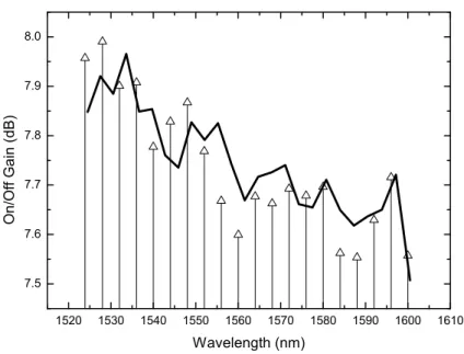
low-power seed optical signal, coupled into a long-cavity semiconductor amplifier, has achieved 400 mW of optical power over a 35 nm spectral window [37]. A 50 nm bandwidth amplifier was obtained with an on/off gain equal to 7 dB. It was also demonstrated that the use of six coherent pumps is less efficient, in terms of flatness, than the use of two incoherent pumps [4]. The signal wavelengths were comprised between 1530 nm and 1605 nm and the transmission occurs over 100 km of optical fiber. Another advantage of using incoherent pumping is the reducing of nonlinear effects, such as Brillouin scattering, four-wave mixing (FWM) induced by pump-pump, pump-signal and pump-noise interactions [38].
The growing maturity of high pump module technologies is providing competitive solutions based on Raman amplification and currently many alternative techniques are being developed to overcome the ordinary one pump and dual pumping methods [39]. In particular, two major techniques are highlighted. First, the use of low power pumping lasers provides gain comparable to the ordinary one pump Raman amplification. This technique is especially interesting for combining commercial and low cost lasers [40]. The second particular technique corresponds to an evolution of the cascaded Raman amplification. Actually, a sixth order cascade Raman amplifier was recently proposed [41]. In the cascade Raman amplification, the pump power is downshifted in frequency by using a pair of fiber Bragg gratings (FBGs) placed in spectral positions multiples of 13 THz, from the pump frequency. In a particular case, the generation of the fiber pump laser is obtained by using only one passive reflector element and distributed reflectors over the long optical fiber, establish by a nonlinear fiber intrinsic effect called Rayleigh backscattering.
1. Introduction
1.3
Objectives and thesis organization
The goal of this thesis is to study the RFA in the scope of modern optical communication systems, accounting for their principal challenges [42]. Specific topics such as, the development of an efficient simulator for Raman amplified links, the gain enlargement and equalization, hybrid Raman/EDFA schemes and the effect of transients are important and thus addressed both theoretically and experimentally.
The work reported here was mainly performed in the facilities of the Instituto de Telecomunicações (IT) in Aveiro and had the advantage of being framed by both portuguese (TECLAR, ARPA, FEFOF, TOMAR-PON) and European projects (BONE, SARDANA and EURO-Fos). A short period training in the National Intitute of Information and Communications Technology (NICT) sitted in Tokyo, Japan, supervised by Professor Nayoa Wada, enabled the access to top laboratorial facilities and the accompliment of important work.
This thesis is organized in six chapters, in which several aspects of Raman amplification in telecommunications are studied.
Chapter 1 provides a background and a motivation for this work and an overview of Raman amplification within the frame of optical communications systems. Raman amplification principles of operation are introduced, being their pros and cons discussed. The most relevant challenges relating this topic are presented as well as state of the art work. Chapter 1 also presents a summary of results provided by a list of published work.
Chapter 2 presents the Raman amplification theory, namely SRS. A mathematical model for propagation in optical fibers is then introduced and the relevance of pumping shemes in optical communications analyzed. Since the computation of solutions is a cumbersone task, a relevant approximation, small-signal approximation, is presented, and its most important results discussed. The effect outside the approximation, pump depletion, is also discussed. An analysis of the noise behaviour of RFA is also presented, being their implications for communications systems discussed.
Chapter 3 is focused on modeling of RFA. Hence, a general mathematical model for multi-pump, multi-signal given by a system of nonlinear ordinary differential equation (ODE) is presented. Possible methodologies to solve the equations are presented and discussed. The latter, can be either numerical (shooting, collocation, etc) or semi-analytical. The use of average power analysis (APA) is introduced and their improvements in terms of accuracy and efficiency discussed. Other qualitative analytical approaches, such as the linearization in the vicinity of critical points or Lyapunov-second methods are also analyzed and applied to the problem of RFA.
Chapter 4 is devoted to the topic of gain enlargement and optimization by allocation of pumps, which is a very important application of RFA. A method based 8
1.4. Summary of results
on an hybrid Genetic Algorithm is introduced. This method uses a combination of an heuristic, GA, with a local search, Nelder-Mead. It is demonstrated that the proper configuration of this method allows a improvement of a factor of 2 in its efficiency. An experimental validation of the gain optimization and gain enlargement is also provided.
Chapter 5 regards the practical application of optical amplifiers in access networks. The work presented is mainly focused on amplifiers transients, RFA and EDFA, in the scope of optical bursty/packeted traffic. The latter were demonstrated to be more penalizing for EDFA, and experimental characterizations were carried on to assess the decays times. Two mitigation solutions based on optical gain clamping are proposed, one based on a feed-back ring and another based on enhanced bidirectional clamping with FBG. Their efficiency for WDM/TDM-PON is also discussed. This chapter also addresses the topic of hybrid Raman/EDFA amplification, namely for C+L band. Some practical situation are assessed, namely WDM ring in rural scenarios. The feasibility of this amplification schemes for normal and resilient modes is also discussed.
This thesis ends with chapter 6 where the main conclusions are summarized and directions for future work are pointed out.
1.4
Summary of results
The most important results accomplished from this thesis are:
• The development of an efficient and accurate simulator for Raman fiber amplifiers using average power analysis and its experimental validation .
• The implementation of a pump allocation algorithm for gain equalization using a combination of genetic algorithm and Nelder Mead method and its experimental validation.
• The assessment of extended and equalized gain in C+L transmission bands using hybrid Raman/EDFA for WDM/TDM PON solutions in rural scenarios.
• The assessment and charaterization of transients, Raman and EDFA and the combination of both in networks with bursty traffic.
• The implementation of mitigation solutions for EDFA transients based on optical gain clamping, suitable for metro and access networks.
• The evaluation of the above mentioned effect of transmission systems at 10 Gb/s. The work accomplished within the period of this thesis resulted in 10 published papers in journals and another under peer revision, 26 conference proceedings and 9
1. Introduction
also a chapter in a book. The work has also originated colaborations within other researchers in the optical communications group, which were also published. The publication are listed bellow .
1.4.1
List of publications
Chapters in books
1. J. Schlesinger, Optical Fibers Research Advances. Nova Science Pub Inc, 2007.
Papers in journals
1. B. Neto, A. Teixeira, N. Wada, and P. André, “Efficient use of hybrid genetic algorithms in the gain optimization of distributed raman amplifiers,” Optics
Express, vol. 15, no. 26, pp. 17 520–17 528, 2007.
2. D. Sperti, P. André, B. Neto, A. Rocha, A. Bononi, F. da Rocha, and M. Facão, “Experimental assessment of some Raman fiber amplifiers solutions for coarse wavelength division multiplexing applications,” Photonic Network
Communications, vol. 16, no. 3, pp. 195–202, 2008.
3. A. Rocha, B. Neto, M. Facao, and P. Andre, “Study of raman amplification with low cost incoherent pumps,” Microwave and Optical Technology Letters, vol. 50, no. 2, pp. 301–303, 2008.
4. P. André, B. Neto, A. Teixeira, and N. Wada, “Raman amplification impact in packet base networks,” Microwave and Optical Technology Letters, vol. 50, no. 12, pp. 3083–3085, 2008.
5. A. Rocha, B. Neto, M. Facao, and P. Andre, “Low cost incoherent pump solution for Raman fiber amplifier,” Optica Applicata, vol. 39, no. 2, pp. 287–293, 2009. 6. J. Reis, B. Neto, P. André, and A. Teixeira, “WDM ring performance
improvement by means of four-wave mixing crosstalk minimization algorithm,”
Microwave and Optical Technology Letters, vol. 51, no. 8, pp. 1949–1952, 2009.
7. B. Neto, J. Ferreira, N. Wada, A. Pinto, and P. André, “Evaluation of the effect of channel add/drop impact on power transients on the performance of a 10-GB/S DWDM transmission system with hybrid EDFA/Raman amplification,”Microwave and Optical Technology Letters, vol. 52, no. 6, pp.1225– 1228, 2010.
8. M. T. M. R. Giraldi, A. M. Rocha, B. Neto, C. Correira, M. E. V. Segatto, M. J. Pontes, A. P. L. Barbero, J. C. W. Costa, M. A. G. Martinez, O. Frazão, 10
1.4. Summary of results
J. M. Baptista, H. M. Salgado, B. M. Marques, A. L. J. Teixeira, P. S. André, “Rayleigh assisted Brillouin effects in distributed Raman amplifiers under saturated conditions at 40 Gb/s,Microwave and Optical Technology Letters, vol. 52, no. 6, pp.1331–1335, 2010.
9. C. Reis, A. Maziotis, C. Kouloumentas, C. Stamatiadis, M. Bougioukos, N. Calabretta, P. Andre, R. Dionisio, B. Neto, H. Dorren, H. Avramopoulos, and A. Teixeira, “All optical synchronous SR flip-flop based on active interferometric devices”, Electronics Letters, vol. 46, no. 10, pp. 709 –710, May 2010.
10. B. Neto, C. Reis, R. P. Dionísio, J. M. Ferreira, J. A. Lazaro, G. Tosi-Beleffi, A. N. Pinto, R. Nogueira, A. Teixeira, J. Prat, P. S. André “Assessment and mitigation of EDFA gain transients in hybrid WDM/TDM PON in the presence of packet based traffic, Optoelectronics, IET, to be published, 2010.
11. B. Neto, A. Klingler, C. Reis, R. P. Dionísio, R. N. Nogueira, A. Teixeira, P. S. André “Enhanced optical gain clamping for upstream packet based traffic on hybrid WDM/TDM-PON using Fiber Bragg Grating, Journal of Optical
Communications and Networking, OSA, submitted, July 2010.
Papers in conference proceedings
1. P. Andre, A. Pinto, A. Teixeira, B. Neto, S. Junior, D. Sperti, F. da Rocha, M. Bernardo, M. Fujiwara, A. Rocha, and M. Facao, “Raman amplification using incoherent pump sources,” in Transparent Optical Networks, 2007. ICTON ’07. 9th
International Conference on, vol. 1, July 2007, pp. 136–139.
2. P. André, A. Rocha, B. Neto, and M. Facão, “Improvement of Raman Amplification Gain Tilt Using Incoherent Pump Sources,” Laser Science, 2007. 3. A. Teixeira, P. Teixeira, B. Neto, R. Nogueira, and P. Andre, “Automatic
apodization profiling of super structured fiber Bragg gratings for OCDMA coding applications,” in Optical Fiber Conference OFC’08, February 2008, pp. JThA29.
4. P. Teixeira, B. Neto, R. Nogueira, P. Andre, and A. Teixeira, “Code cardinality maximization using highly reflective SSFBG with optimum apodization profiles,” in 10th Anniversary International Conference on Transparent Optical
Networks, 2008. ICTON 2008, 2008, pp. 55–57.
5. C. Reis, A. M. Rocha, B. Neto, N. Wada, P. Andre, “Raman amplification in high 10 Gbit/s and 40 Gbit/s packet optical networks,” in Mediterranean Winter, 2008.
ICTON-MW 2008. 2nd ICTON., 11-13, pp. 1 –4.
1. Introduction
6. J. Andrade, B. Neto, A. Rocha, C. Reis, A. Teixeira, and P. Andre, “Raman amplification in the context of next-generation passive optical networks,” in
Mediterranean Winter, 2008. ICTON-MW 2008. 2nd ICTON, 11-13 2008, pp. 1
–4.
7. J. Reis, B. Neto, P. Andre, and A. Teixeira, “WDM ring performance improvement by means of a nonlinear effects crosstalk minimization algorithm,” in Optical Fiber Communication - incudes post deadline papers, 2009. OFC 2009.
Conference on, 22-26 2009, pp. 1 –3.
8. A. Rocha, B. Neto, A. Martins, G. Incerti, D. Forin, G. Bellefi, M. Facao, J. Pinto, A. Teixeira, R. Nogueira, M. Lima, and P. Andre, “The effect of high power propagation in bended fibers,” in Telecommunications, 2009. ConTEL 2009. 10th
International Conference on, 8-10 2009, pp. 303 –304.
9. P. Coelho, J. Reis, B. Neto, P. Andre, and A. Teixeira, “Monitoring of fiber nonlinearities in wdm based passive optical networks,” in Telecommunications,
2009. ConTEL 2009. 10th International Conference on, 8-10 2009, pp. 277 –281.
10. P. Andre, B. Neto, C. Reis, A. Rocha, N. Wada, G. Beleffi, and A. Teixeira, “Raman amplification challenges for next generation networks,” in Transparent Optical
Networks, 2009. ICTON ’09. 11th International Conference on, june 2009, pp. 1 –2.
11. C. Reis, B. Neto, R. Dionisio, G. Incerti, G. Tosi-Beleffi, D. Forin, A. Rocha, A. Teixeira, and P. Andre, “Transience analysis of bursty traffic with erbium doped fiber amplifiers,” in Transparent Optical Networks, 2009. ICTON ’09. 11th
International Conference on, june 2009, pp. 1 –3.
12. J. Reis, B. Neto, P. Andre, and A. Teixeira, “Optimization of passive optical networks by means of fiber nonlinearities interference reduction,” in Transparent
Optical Networks, 2009. ICTON ’09. 11th International Conference on, june 2009, pp.
1 –4.
13. B. Neto, M. Rodrigues, E. Rocha, and P. Andre, “Stability analysis of raman propagation equations,” in Transparent Optical Networks, 2009. ICTON ’09. 11th
International Conference on, june 2009, pp. 1 –4.
14. B. Neto, A. Klingler, C. Reis, J. Girao, A. Teixeira, and P. Andre, “EDFA transient assessment for bursty traffic,” in ICTON Mediterranean Winter Conference, 2009.
ICTON MW 2009. 3rd, 10-12 2009, pp. 1 –4.
15. B. Neto, C. Reis, A. Teixeira, P. André,
and N. Wada, “Gain equalization technique for raman amplification systems based on the hybrid optimization algorithm,” in Microwave and Optoelectronics
Conference (IMOC), 2009 SBMO/IEEE MTT-S International, 3-6 2009, pp. 687 –689.
1.4. Summary of results
16. M. Rocco Giraldi, A. M. Rocha, B. Neto, C. Correia, M. Segatto, M. Pontes, A. Barbero, J. Costa, M. Martinez, O. Frazao, J. Baptista, H. Salgado, M. Marques, A. Teixeira, and P. Andre, “Brillouin effects in distributed raman amplifiers under saturated conditions,” in Microwave and Optoelectronics International
Conference (IMOC), 2009 SBMO/IEEE MTT-S, 3-6 2009, pp. 841 –845.
17. N. Pavlovic, A. Baptista, B. Neto, A. Rocha, P. Andre, D. Form, G. Beleffi, J. Lazaro, J. Prat, and A. Teixeira, “Demonstration of improved osnr in ring-based pons with remotely pumped amplification,” in OptoElectronics and
Communications Conference, 2009. OECC 2009. 14th, 13-17 2009, pp. 1 –2.
18. P. S. Andre, A. M. Rocha, B. Neto, A. Martins, M. Facao, J. L. Pinto, A. L. J. Teixeira, R. N. Nogueira, M. J. Lima, G. Incerti, D. Forin, G. T. Beleffi“Optical fiber bending limits for optical fiber infraestructures,” in
AFRICON, 2009. AFRICON ’09., 23-25, pp. 1 –3.
19. B. Neto, C. Reis, A. Rocha, J. P. Girão, R. P. Dionísio, , S. Chatzi, F. Bonada, J. Lazaro, J. A. and, and A. L. J. Teixeira, “Impact of transient response of optical amplifiers operating with burst traffic,” in 7th Conference on Telecommunications,
2009. Conftele ’09., vol. 1, May 2009, pp. —.
20. A. Martins, A. M. Rocha, B. Neto, A. Teixeira, M. Facão, R. N. Nogueira, M. Lima, P. S. André, “Modeling of Bend Losses in Single-Mode Optical Fibers,” in 7th
Conference on Telecommunications, 2009. Conftele ’09., vol. 1, May 2009, pp.
21. B. Neto, C. Reis, A. Rocha, A. L. J. Teixeira, N. Wada, and P. S. André, “Transience response of traffic based on optical packets with optical amplifiers,” in Networks
and Optical Communications, 2009. NOC ’09. 14th European Conference on, vol. 1,
June 2009, pp. 545–550.
22. N. B. Pavlovic, A. Baptista, B. Neto, A. Rocha, D. Forin, J. A. Lazaro, J. Prat, and A. L. J. Teixeira, “Joint raman and remote add/drop amplification scheme for next generation pons,” in Networks and Optical Communications, 2009. NOC ’09.
14th European Conference on, vol. 1, June 2009, pp. 435–442.
23. C. Reis, R. Dionisio, B. Neto, A. Teixeira, and P. Andre, “All-optical XOR based on integrated MZI-SOA with co-and counter-propagation scheme,” in ICTON
Mediterranean Winter Conference, 2009. ICTON-MW 2009. 3rd. IEEE, 2010, pp. 1–4.
24. B. Neto, R. P. Dionísio, A. M. Rocha, C. Reis, S. Chatzi, F. Bonada, J. A. Lazaro, A. L. J. Teixeira, and P. S. André, “C+L band extended reach next generation access networks through raman amplification: assessment in rural scenario,” in 13
1. Introduction OptoElectronics and Communications Conference, 2010. OECC 2010. 15th, 5-9 2010,
pp. 1 –2.
25. B. Neto, A. Rocha, J. P. Girão, R. P. Dionísio, C. Reis, S. Chatzi, F. Bonada, J. A. Lazaro, A. L. J. Teixeira, and P. S. André, “C+L band gain equalization for extended reach wdm-ring pon using hybrid raman/in line edfa amplification,” in Transparent Optical Networks, 2010. ICTON ’10. 12th International Conference on, vol. 1, June 2010, pp. 136–139.
26. B. Neto, A. Rocha, J. P. Girão, R. P. Dionísio, C. Reis, S. Chatzi, F. Bonada, J. Lazaro, J. A. and, and A. L. J. Teixeira, and P. S. André, “Comparative analysis of hybrid in line edfa/raman with simple Raman amplification in WDM ring pon for C+L band,” in Networks and Optical Communications, 2010. NOC ’10. 15th
European Conference on, vol. 1, June 2010, pp. —.
References
[1] J. Prat, Next-Generation FTTH Passive Optical Networks: Research Towards Unlimited
Bandwidth Access. Springer Verlag, 2008.
[2] T. ITU, “694.2,” Spectral grids for WDM applications: CWDM wavelength grid (6.02). [3] M. Bredol, D. Leers, L. Bosselaar, and M. Hutjens, “Improved model for OH absorption in optical fibers,” Lightwave Technology, Journal of, vol. 8, no. 10, pp. 1536–1540, 1990.
[4] W. Mostert and D. Emms, “O band wdm,” June 2008,
http://www.cable360.net/ct/sections/features/30007.html.
[5] E. Desurvire, Erbium-doped fiber amplifiers: principles and applications. Wiley New York, 1994.
[6] M. Digonnet, Rare-earth-doped fiber lasers and amplifiers. CRC, 2001.
[7] M. Wright and G. Valley, “Yb-doped fiber amplifier for deep-space optical communications,” Journal of Lightwave Technology, vol. 23, no. 3, p. 1369, 2005. [8] G. Valley, “Modeling cladding-pumped Er/Yb fiber amplifiers,” Optical Fiber
Technology, vol. 7, no. 1, pp. 21–44, 2001.
[9] P. Andre, B. Neto, C. Reis, A. Rocha, N. Wada, G. Beleffi, and A. Teixeira, “Raman amplification challenges for next generation networks,” in Transparent Optical
Networks, 2009. ICTON ’09. 11th International Conference on, june 2009, pp. 1 –2.
1.4. References
[10] D. Zimmerman and L. Spiekman, “Amplifiers for the masses: Edfa, edwa, and soa amplets for metro and access applications,” Lightwave Technology, Journal of, vol. 22, no. 1, pp. 63 – 70, jan. 2004.
[11] K. C. Reichmann, P. P. Iannone, X. Zhou, N. J. Frigo, and B. R. Hemenway, “240-km CWDM Transmission Using Cascaded SOA Raman Hybrid Amplifiers With 70-nm Bandwidth,” Photonics Technology Letters, IEEE, vol. 18, no. 2, pp. 328–330, 2006.
[12] S. Zsigmond, H. Furukawa, and N. Wada, “Scalability study of SOA based optical switch for optical packet networks,” in Photonics in Switching, 2009. PS’09.
International Conference on. IEEE, 2009, pp. 1–2.
[13] C. Reis, R. Dionisio, B. Neto, A. Teixeira, and P. Andre, “All-optical XOR based on integrated MZI-SOA with co-and counter-propagation scheme,” in ICTON
Mediterranean Winter Conference, 2009. ICTON-MW 2009. 3rd. IEEE, 2010, pp. 1–4.
[14] C. Headley and G. Agrawal, Raman amplification in fiber optical communication
systems. Elsevier Academic Press, 2005.
[15] M. Yan, J. Chen, W. Jiang, J. Li, J. Chen, and X. Li, “Automatic design scheme for optical-fiber raman amplifiers backward-pumped with multiple laser diode pumps,” Photonics Technology Letters, IEEE, vol. 13, no. 9, pp. 948–950, Sep 2001. [16] J. Bromage, P. Winzer, and R. Essiambre, “Multiple path interference and its
impact on system design,” Raman Amplifiers for Telecommunications 2, pp. 491–568, 2004.
[17] Y. Awaji, H. Furukawa, N. Wada, E. Kong, P. Chan, and R. Man, “Guidelines for amplification of optical packets in WDM environment regarding impact of transient response of erbium-doped fiber amplifier,” Computer Networks, vol. 52, no. 10, pp. 2087–2093, 2008.
[18] C. Raman and K. Krishnan, “A new type of secondary radiation,” Nature, vol. 121, no. 3048, p. 501, 1928.
[19] R. Stolen and E. Ippen, “Raman gain in glass optical waveguides,” Applied Physics
Letters, vol. 22, p. 276, 1973.
[20] Y. Aoki, S. Kishida, K. Washio, and K. Minemura, “Bit error rate evaluation of optical signals amplified via stimulated Raman process in an optical fibre,”
Electronics Letters, vol. 21, p. 191, 1985.
1. Introduction
[21] E. Woodbury and W. Ng, “Ruby laser operation in the near IR,” Proc. Ire, vol. 50, no. 11, p. 2367, 1962.
[22] S. Namiki, K. Seo, N. Tsukiji, and S. Shikii, “Challenges of Raman amplification,”
Proceedings of the IEEE, vol. 94, no. 5, pp. 1024–1035, 2006.
[23] J. Hu, B. Marks, and C. Menyuk, “Flat-gain fiber raman amplifiers using equally spaced pumps,” Lightwave Technology, Journal of, vol. 22, no. 6, pp. 1519 – 1522, june 2004.
[24] M. Giltrelli and M. Santagiustina, “Semianalytical approach to the gain ripple minimization in multiple pump fiber Raman amplifiers,” IEEE Photonics
Technology Letters, vol. 16, no. 11, pp. 2454–2456, 2004.
[25] S. Cui, J. Liu, and X. Ma, “A novel efficient optimal design method for gain-flattened multiwavelength pumped fiber raman amplifier,” Photonics Technology
Letters, IEEE, vol. 16, no. 11, pp. 2451 –2453, nov. 2004.
[26] H. Kidorf, K. Rottwitt, M. Nissov, M. Ma, E. Rabarijaona, T. Ltd, and N. Eatontown, “Pump interactions in a 100-nm bandwidth Raman amplifier,”
IEEE Photonics Technology Letters, vol. 11, no. 5, pp. 530–532, 1999.
[27] J. Bromage, “Raman amplification for fiber communications systems,” Journal of
Lightwave Technology, vol. 22, no. 1, p. 79, 2004.
[28] A. Rocha, B. Neto, A. Martins, G. Incerti, D. Forin, G. Bellefi, M. Facao, J. Pinto, A. Teixeira, R. Nogueira, M. Lima, and P. Andre, “The effect of high power propagation in bended fibers,” in Telecommunications, 2009. ConTEL 2009. 10th
International Conference on, 8-10 2009, pp. 303 –304.
[29] P. Andre, M. Facao, A. Rocha, P. Antunes, and A. Martins, “Evaluation of the fuse effect propagation in networks infrastructures with different types of fibers,” in Optical Fiber Communication (OFC), collocated National Fiber Optic Engineers
Conference, 2010 Conference on (OFC/NFOEC), 21-25 2010, pp. 1 –3.
[30] D. Chen, T. Xia, G. Wellbrock, J. Peterson, D.L., S. Park, E. Thoen, C. Burton, J. Zyskind, S. Penticost, and P. Mamyshev, “"long span" 10 times;160 km 40 gb/s line side, oc-768c client side field trial using hybrid raman/edfa amplifiers,” in
Optical Communication, 2005. ECOC 2005. 31st European Conference on, 25-29 2005,
pp. 15 – 16 vol.1.
[31] I. T. Monroy, R. Kjaer, B. Palsdottir, A. M. J. Koonen, and P. Jeppesen, “10 gb/s bidirectional single fibre long reach pon link with distributed raman amplification,” in Optical Communications, 2006. ECOC 2006. European Conference
on, 24-28 2006, pp. 1 –2.
1.4. References
[32] M. Schneiders, S. Vorbeck, R. Leppla, E. Lach, M. Schmidt, S. Papernyi, and K. Sanapi, “Field transmission of 8 times;170 gbit/s over high loss ssmf link using third order distributed raman amplification,” in Optical Fiber Communication
Conference, 2005. Technical Digest. OFC/NFOEC, vol. 6, 6-11 2005, p. 3 pp. Vol. 5.
[33] Y. Emori, K. Tanaka, and S. Namiki, “100 nm bandwidth flat-gain raman amplifiers pumped and gain-equalised by 12-wavelength-channel wdm laser diode unit,” Electronics Letters, vol. 35, no. 16, pp. 1355–1356, 1999. [Online]. Available: http://link.aip.org/link/?ELL/35/1355/1
[34] B. Han, X. Zhang, G. Zhang, Z. Lu, and G. Yang, “Composite broad-band fiber raman amplifiers using incoherent pumping,” Opt. Express, vol. 13, no. 16, pp. 6023–6032, 2005. [Online]. Available: http://www.opticsexpress.org/abstract.cfm?URI=oe-13-16-6023
[35] T. Zhang, X. Zhang, and G. Zhang, “Distributed fiber Raman amplifiers with incoherent pumping,” IEEE Photonics Technology Letters, vol. 17, no. 6, pp. 1175– 1177, 2005.
[36] S. Wen, “Design of the pump power spectrum for the distributed fiber Raman amplifiers using incoherent pumping,” Optics Express, vol. 14, no. 9, pp. 3752– 3762, 2006.
[37] D. Vakhshoori, M. Azimi, P. Chen, B. Han, M. Jiang, K. Knopp, C. Lu, Y. Shen, G. Rodes, S. Vote et al., “Raman amplification using high-power incoherent semiconductor pump sources,” in Optical Fiber Communication Conference, 2003. [38] X. Zhou, M. Birk, and S. Woodward, “Pump-noise induced FWM effect and
its reduction in a distributed Raman fiber amplifier,” IEEE Photonics Technology
Letters, vol. 14, no. 12, pp. 1686–1688, 2002.
[39] D. I. Chang, D. S. Lim, M. Y. Jeon, H. K. Lee, K. H. Kim, and T. Park, “Dual-wavelength cascaded raman fibre laser,” Electronics Letters, vol. 36, no. 16, pp. 1356–1358, 2000. [Online]. Available: http://link.aip.org/link/?ELL/36/1356/1 [40] A. Teixeira, P. Andre, S. Stevan, T. Silveira, A. Tzanakaki, and I. Tomkos, “Raman
Amplification based on Multiple Low-Power lasers,” in International Conference
on Internet and Web Applications and Services/Advanced International Conference on Telecommunications, 2006. AICT-ICIW’06, 2006, pp. 85–85.
[41] S. Papernyi, V. Ivanov, Y. Koyano, and H. Yamamoto, “Sixth-order cascaded Raman amplification,” in Optical Fiber Commun. Conf.(OFC), Anaheim, CA, 2005. [42] J. Schlesinger, Optical Fibers Research Advances. Nova Science Pub Inc, 2007.
Chapter 2
Raman amplification theory
2.1
Introduction
To understand the basics behind Raman amplification, it is necessary to understand the phenomenon that describes it, stimulated Raman scattering (SRS). A complete description of Raman amplification would approach thoroughly nonlinear optics and complex mathematics. We choose an intermediate approach that explains the physics of the amplifiers but keeping in mind an imediate application using a telecommunication perspective. Thus, the work described in four major references, Headley and Agrawal [1], J. Bromage [2]and Auyeung and Yariv [3], is followed in order to provide a description as as relevant as possible.
The theory is approached for the first time and a brief description of spontaneous and stimulated Raman scattering is provided in a quantum mechanical point of vue. The Raman gain coefficient is introduced analytically and the efficiency of Raman amplification is discussed for several types of fibers. Then, single pump amplification is approached and the pumping architecture is discussed. The physical model to predict the power evolution for data and pump signals is also presented. The model is mathematically described by a set of coupled nonlinear differential equations for which no analytical solution is available. Nevertheless, the topic of Raman amplifiers modeling will be discussed with more detail in chapter 3. However, to provide some physical insight, simplifications can be made, in particular, the one pump and one signal situation small-signal approximation. An analytical approach that follows the work developed by Auyeung and Yariv that considers pump depletion is presented, although this method is only valid for forward single pumping.
We proceed with a description of the performance limiting factors of Raman amplifiers, which are amplified spontaneous emission, single and double Rayleigh backscattering, also known as multipath interference (MPI) and pump noise transfer. Since amplified spontaneous emission is the dominant effect, it is examined with more detail and the related concept of noise figure and effective noise figure are approched, being their temperature dependence analysed for broadband amplifiers.