CONTROL SYSTEM FOR ATLAS TileCal HVRemote BOARDS
F. Martins
∗, L. Gurriana, L. Seabra, LIP, Portugal
G. Evans
1, A. Gomes
2, A. Maio
2, C. Rato, J. Sabino, J. Soares Augusto
3Faculdade de Ciências da Universidade de Lisboa, Portugal
1
also at BioISI, Universidade de Lisboa, Portugal
2also at LIP, Portugal
3
also at Inesc-ID, Portugal
Abstract
For the high luminosity LHC one of the proposed solu-tions for upgrading the high voltage (HV) system of the ATLAS central hadron calorimeter (TileCal), consists in removing the HV regulation boards from the detector and deploying them in a low-radiation room where there is per-manent access for maintenance. This option requires many ∼100 m long HV cables but removes the requirement of radiation hard boards.
This solution simplifies the control system of the HV reg-ulation cards (called HVRemote). It consists of a Detector Control System (DCS) node linked to 256 HVRemote boards through a tree of Ethernet connections. Each HVRemote includes a smart Ethernet transceiver for converting data and commands from the DCS into serial peripheral interface (SPI) signals routed to SPI-capable devices in the
HVRe-mote. The DCS connection to the transceiver and the control
of some SPI-capable devices via Ethernet has been tested successfully.
A test board (HVRemote-Ctrl) with the interfacing sub-system of the HVRemote was fabricated. It is being tested through SPI-interfaces and several devices were already val-idated. A next version adds a few more ADC/DAC devices for checking their suitability for the final design.
INTRODUCTION
The Tile Calorimeter (TileCal) [1] is the central hadronic calorimeter of ATLAS [2], one of the two multi-purpose experiments at the Large Hadron Collider (LHC) at CERN. The high luminosity LHC (HL-LHC) aims to deliver a lu-minosity increased by a factor of 5 to 10 compared to the LHC design value [3]. The HL-LHC environment presents several challenges for TileCal and an upgrade program is being prepared for the detector. TileCal uses iron plates as absorber and plastic scintillating tiles as the active material. Light produced in the scintillators is transmitted by wave-length shifting fibres to photomultiplier tubes (PMTs). An electronic system currently being upgraded is that in charge of the control and distribution of high-voltage (HV) to the approximately 104PMTs of the TileCal detector. In the
cur-rent operational version, its core comprises two cards [4]: the HVOpto and the HVMicro. In the current ATLAS setup, this system is located inside the detector, so it operates under high doses of radiation. Current TileCal HV electronics is
in operation for more than 10 years and, as a result, is ageing despite its design accounted for radiation hardness. Another severe constraint is the difficulty in maintaining and replac-ing faulty HVOpto or HVMicro cards: it is never possible to replace them when the LHC is running, and the maintenance is possible only during the yearly winter shutdowns.
To alleviate these constraints, the solution proposed for the upgrade [5, 6] moves the TileCal’s HVOpto electronic control system from the detector innards, to a location in the USA15 room which is a low radiation environment far away (100 m) from the detector. This will improve the lifetime of the system and provides for immediate maintenance and replacement. On the other hand, the HVRemote1board will
now be connected to the PMTs through several 100 m long cables, which may worsen slightly their stability and noise levels. Since the current electronic design is about 20 years old, some components in the HVOpto, such as the ADCs and DACs2, are obsolete and have to be replaced by modern alternatives.
In addition, an HV system was developed by Argonne Na-tional Laboratory team, which keeps the HV regulation and distribution electronics in the detector [7], and is a possible alternative solution for the upgrade.
In this note we describe the ongoing work regarding the upgrade of the control system of the HV cards for the
HVRe-mote version. Most of the tests presented here, which aim at
evaluating and validating several design options, were based in prototype boards, called HVRemote-Ctrl cards, which contain downsized replicas of the hardware of the commu-nications interface of the full HVRemote board. One of the
HVRemote-Ctrl cards is described below.
THE HVRemote CONTROL SYSTEM
The HVRemote Control Path and Hardware
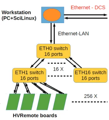
The architecture of the upgraded electronics system of the TileCal is shown in Fig. 1. The control master is a PC/workstation configured as a node of the DCS of ATLAS. The DCS commands sent to, and the data read from the
HVRemote boards, flow through a tree of Ethernet links,
connecting the PC and 256 boards, each of these managing 48 PMT channels.
1The "old" HV system, now in operation is referred to as HVOpto and the
upgraded system is referred to as HVRemote.
2DAC refers to a generic Digital-Analogue Converter; ADC refers to a
generic Analogue-Digital Converter.
Content from this w ork ma y be used under the ter ms of the CC BY 3.0 licence (© 2017). An y dis tribution of this w ork mus tmaintain attr ibution to the author(s), title of the w ork, publisher ,and
The control software consists of DCS (high-level com-mands), C++ and Python programs, running in the PC, which use the DCS API (Application Programming Interface), and also C programs running in the Tibbo EM1206 modules (de-scribed below). Each HVRemote board includes one Tibbo EM1206 module which is used to read commands from the Ethernet channel, convert them into raw digital signals and send them to HVRemote’s digital control circuits through a SPI link. The Tibbo EM1206 modules also manage the reverse data flow (from the HVRemote to the upstream DCS computers.)
Figure 1: Architecture of the HVRemote control tree.
The HVRemote-Ctrl Testing Card
To evaluate the supervising and control system of the
HVRemote before this complex and costly board is fully
assembled, a test card was built, called HVRemote-Ctrl (Figs. 2 and 3), which has the same control/interfacing components of the HVRemote, but misses the front-end electronics of the 48 PMTs. This allows the testing of both the digital control hardware and the Tibbo module, and the assessment of the transfer speeds. The HVRemote-Ctrl has already been assembled and tested. The DAC and ADC in this card are platforms for evaluating test algorithms to be applied to the
HVRemote board in the future.
The hardware of theHVRemote-Ctrl card A DC level
translator MAX3002 provides compatibility for the 3.3 V and 5 V signals shared by the Tibbo module and the CMOS hardware. The HVRemote-Ctrl card has a 16-bit port ex-pander with SPI interface (MCP23S17), a 12-bit DAC (DAC7568), a 16-bit analogue multiplexer (MPC506), an in-strumentation amplifier (INA128), a 12-bit ADC (TLV2541),
a temperature sensor (TMP17) and a voltage reference (AD589).
These are the same components (but in less quantity), and interfacing architecture, found in the HVRemote full card undergoing fabrication at present. The HVRemote-Ctrl card also allows applying the histogram test to each individual data converter using several digital pseudorandom uniform noise generators (UNGs). In some of the current test settings used with the card, an Arduino replaces the commercial mod-ule EM1206+RJ203 (shown in the centre of Fig. 2) in the role of SPI master and so the DC/DC converter MAX3002 is not needed and is tested separately.
To access and control the electronic components in the
HVRemote-Ctrl card, the serial data from the SPI is
con-verted to a parallel format. This is required due to the pin-count constraints of the Tibbo module. That serial-to-parallel conversion occurs in the MCP23S17 expander: the data in parallel configures the DAC, ADC and multiplexer’s parameters (Fig. 4). The MCP23S17 has 16 general pur-pose input/output pins (two byte-wide ports, GPA and GPB) backed and configured by several internal registers. The signals relayed by the expander link the Tibbo module to the functional devices. There are four lines dedicated to the SPI protocol (CS, SCK, SI and SO) which interface with the
Tibbo module.
Software for testing theHVRemote-Ctrl card A user
interface written in Python was developed to test the board’s components. The test of the expander has already been com-pleted with success. In the user interface window for testing the expander, the user sends 16 bits as two-byte strings (cor-responding to the two ports, GPA and GPB) and the data written in the ports will be sent back, received by the Arduino
Uno and saved in a file.
The communication with the expander is done through the Arduino IDE. Since the user interface is developed in Python and runs in the PC, a logical serial communication channel is established between the Arduino and the Python user interface, such that this interface can send/receive the data to/from the expander which is in the HVRemote-Ctrl card.
In the user interface, the received data is assembled in an array, processed and saved to a file. All the read/write tests already done ended with success, and so it was concluded that it is safe to use the expander to configure and test the other components in the HVRemote-Ctrl card.
Testing of converters with pseudorandom noise gen-erators and histogram tests The components in the
HVRemote-Ctrl card have already been fully tested. The
static characterization of both DACs and ADCs was done with histogram tests, performed with two digital pseudoran-dom uniform noise generators (NGs): the Mersenne-Twister algorithm for the uniform NG [8] and the Box-Muller algo-rithm for the Gaussian NG [9]. The technique has proven to be a powerful method to characterize converters [10, 11].
Content from this w ork ma y be used under the ter ms of the CC BY 3.0 licence (© 2017). An y dis tribution of this w ork mus tmaintain attr ibution to the author(s), title of the w ork, publisher ,and
Figure 2: Protocols in the HVRemote monitoring, supervising and control system. The first HVRemote-Ctrl prototype is shown.
Figure 3: Simplified block diagram of the HVRemote-Ctrl card. Not all signals are shown.
Figure 4: MCP23S17 signals in the HVRemote-Ctrl card.
In the first step, the offset voltage and gain error of the converter are obtained. After the correction of these errors, the differential (DNL) and integral (INL) non-linearities are calculated. The evaluation of the static errors profile of the
ADCs and DACs is important to the calibration of the HV levels applied to the PMTs.
The user interfaces for orderly applying these tests and characterizing the converters are finished and the test algo-rithms are fully operational and have already been used.
Evaluation of the Tibbo EM1206+RJ203 Module
and Connection with the DCS System
Along with the testing of the hardware used in the inter-face of the HVRemote card, the digital communication link between the DCS system and the HVRemote interface have been fully tested. This means that the Ethernet link between the DCS and the Tibbo module, as well as the operation of this module acting as a SPI Master device, have been tested. This task comprises the two channels and protocols shown in Fig. 2. The important systems in this test task are the
Tibbo module EM12016+RJ203 (or the evaluation board),
the DCS software and the MCP23S17 expander.
Testing Ethernet communication with theTibbo mod-ule In preliminary tests aiming to probe the Ethernet in-terfacing solution, a Tibbo EM1206-EV evaluation board was used and, in more recent tests, the Tibbo module EM12016+RJ203 itself (see Fig. 2). One of these modules will be soldered to each HVRemote. Tibbo supplies an
inte-Content from this w ork ma y be used under the ter ms of the CC BY 3.0 licence (© 2017). An y dis tribution of this w ork mus tmaintain attr ibution to the author(s), title of the w ork, publisher ,and
grated development system for the board, which includes C libraries for sockets programming and SSH communications, two important libraries for our work. Tibbo also supplies a standalone tool, the IO Ninja, which allows testing the Eth-ernet communication channel between the Tibbo module, or evaluation board, and the PC.
The Tibbo module is programmed either in C or in BASIC. A raw Ethernet client using sockets was developed in C and deployed in the module. It succeeded in communicating with an Ethernet master in the PC, programmed in Python, and also worked flawlessly as an Ethernet/sockets master when using the IO Ninja.
Interfacing DCS withHVRemote-Ctrl The DCS
sys-tem was installed and runs with full functionality in a work-station in our laboratory. This platform was used to perform communication tests. The main goal was to exercise the hand-shaking between DCS and the Tibbo Ethernet hard-ware.
A DCS user interface which sends/receives commands and data to/from the Tibbo module has been developed. These commands are applied to external hardware – the MCP23S17 expander –, a process that simulates the access to the HVRemote interface through an SPI channel. In Fig. 5 it is shown a small part of a DCS control panel prepared to drive each channel of the HVRemote board, which was developed using a supervision, control and data acquisition system, the WinCC Open Architecture, belonging to the SCADA SIMATIC development system [12].
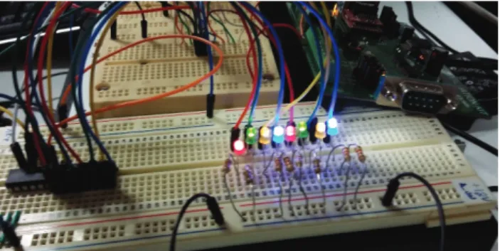
Before the HVRemote-Ctrl board was fabricated, these tests were performed in a setup where the Tibbo module communicated with a MCP23S17 expander mounted in a breadboard (Fig. 6).
Figure 5: Partial view of the WinCC DCS interface devel-oped for the HVRemote card.
Figure 6: Tibbo evaluation card communicating with an MCP23S17 through an SPI channel. The Tibbo evaluation card is driven by DCS commands coming from the worksta-tion.
TheTibbo module and the SPI interface The
perfor-mance of the SPI interface in the Tibbo module was tested in several setups. For instance, SPI connection with two devices in a same SPI bus was established using two
Ar-duino boards as SPI slaves, because the module will have
to manage three MCP23S17 port expanders when linked to the full HVRemote card. In Fig. 7 it is shown a test signal where the SPI clock in the Tibbo was set to a frequency of 200 kHz.
Figure 7: SPI signal (MOSI or SI) during communication. The transmission clock in the Tibbo was set to a period of about 5 μs (2 periods per oscilloscope division in this image).
RESULTS AND CONCLUSION
The development of the HVRemote was driven by knowl-edge gained from evaluating the HVRemote-Ctrl card. The following tasks have been completed:
• Development and assembly of the HVRemote-Ctrl card, to evaluate the digital control and supervising system. This prototype card is already partially tested (Fig. 2). • Development, in Python, of a panel to manage the
HVRemote-Ctrl cards. Content from this w ork ma y be used under the ter ms of the CC BY 3.0 licence (© 2017). An y dis tribution of this w ork mus tmaintain attr ibution to the author(s), title of the w ork, publisher ,and
• Evaluation of the Tibbo EMS1206 module as a suitable Ethernet controller for the HVRemote board.
• Evaluation of the Tibbo EMS1206 module as SPI mas-ter, using multiple microcontrollers (Arduinos) config-ured as SPI slaves.
• Development of a DCS control panel, underlying func-tions, and establishment of Ethernet communications between DCS and the Tibbo module (Fig. 5).
The speeds measured in both Ethernet and SPI communica-tions with the Tibbo module are suitable to monitor in real time all the 256 HVRemote boards and∼104PMTs in the TileCal (each PMT is monitored every few seconds). The
assembly of a prototype of a full HVRemote card is almost finished and the software already developed will be adapted and scaled to target that board instead of the HVRemote-Ctrl test board.
ACKNOWLEDGEMENTS
This work is funded in part by the "Fundação para a Ciên-cia e a Tecnologia", Portugal, under the project "Colaboração na Experiência ATLAS", CERN/FIS-NUC/0005/2015.
REFERENCES
[1] ATLAS TileCal Collaboration, "Tile Calorimeter Technical Design Report", ATLAS Internal Note, CERN/LHCC/96-42 (1996).
[2] ATLAS Collaboration, "The ATLAS Experiment at the CERN Large Hadron Collider", 2008 JINST 3 S08003. [3] ATLAS Collaboration, "ATLAS Phase-II Upgrade Scoping
Document", CERN-LHCC-2015-020, (2015).
[4] R. Chadelas et al., "High voltage distributor system for the Tile hadron calorimeter of the ATLAS detector", ATLAS-TILECAL-2000-003, 2000, https://cds.cern. ch/record/436230
[5] F. Vazeille, "Performance of a remote High Voltage power supply for the Phase II upgrade of the ATLAS Tile Calorime-ter", JINST 11 C02050, 2016.
[6] A. Gomes, "The new front-end electronics for the ATLAS Tile Calorimeter Phase 2 Upgrade", JINST 11 C02015, 2016.
[7] G. Drake, "The New Front-End Electronics for
the ATLAS Tile Calorimeter Phase 2 Upgrade",
ATLAS note ATL-TILECAL-PROC-2015-023,
https://cds.cern.ch/record/2114792
[8] M. Matsumoto, and, T. Nishimura, "Mersenne Twister: A 623-Dimensionally Equidistributed Uniform Pseudorandom Number Generator", ACM Transactions on Modeling and Computer Simulation, vol.8, no. 1, pp.3–30, 1998.
[9] D.-U. Lee, J. D. Villasenor, W. Luk and P. H. W. Leong, "A Hardware Gaussian Noise Generator Using the Box-Muller Methods and Its Error Analysis", IEEE Transactions on Com-puters, vol. 55, no. 6, pp. 659-671, June 2006.
[10] J. Alves and G. Evans, "Digital Pseudorandom Uniform Noise Generator for ADC Histogram Test", DCIS 2015 – XXX Conference on Design of Circuits and Integrated Systems, pp. 1- 6, Estoril, Portugal, November 2015, DOI: 10.1109/DCIS.2015.7388592.
[11] J. D. Alves and G. Evans, "A Digital Pseudorandom Uniform Noise Generator for ADC Built-In Self-Test", 2015 10th IEEE International Conference on Design & Technology of Integrated Systems in Nanoscale Era (DTIS), pp. 1-5, Naples, Italy, April 2015.
[12] http://w3.siemens.com/mcms/human-machine-interface/en/visualization-software/scada/
pages/default.aspx, https://en.wikipedia.org/
wiki/WinCC, (Siemens, SIMANTEC SCADA system), January 2017. Content from this w ork ma y be used under the ter ms of the CC BY 3.0 licence (© 2017). An y dis tribution of this w ork mus tmaintain attr ibution to the author(s), title of the w ork, publisher ,and