Ângela Marisa Pereira Carvalho
Development of nanostructured and bioactive surfaces
onto ceramic substrates
Development of nanostructured and bioactive surfaces
onto ceramic substrates
Work presented to the Faculty of Engineering of the University of Porto as part of the requirements for the Degree of Master in Biomedical Engineering under the supervision of Professor Fernando Jorge Monteiro from Faculty of Engineering of the University of Porto, and having Dr. Alejandro Pelaez-Vargas from INEB, as advisor
Recent developments in biomaterials are associated to changes in concepts and applications. Some biomaterials that were used in the past for a certain application may not be used nowadays due to improvements or substitutions for a better material. The constant search for a biomaterial that might last for the whole patient‟s life is still a challenge in almost every clinical application.
In oral surgery, teeth are likely candidates for replacement by artificial components such as orthodontic implants. Overall, this approach is highly successful; however, restorative surgery involving implants generally have a finite lifespan and may require replacement at a future time. The main material used as implant in dentistry is titanium. This has shown good properties to be applied as a dental implant, as the fact that it promotes osseointegration; it is biocompatible and has excellent mechanical properties. However, titanium is also associated to some disadvantages. This material is associated with allergic reactions in some persons, gingival tarnishing and peri-implantitis, an infection in the support tissues around the implant provoked by bacterial colonization and reduced tissue attachment that causes bone loss.
In this work, a new approach to modify ceramic (zirconia) dental implants surface is presented. The main goal is to use a bioactive and micropatterned silica coating to increase osteointegration and cell modulation for guided tissue regeneration and to diminish the bacterial adhesion and proliferation at the implant-tissue interface, eliminating also gingival tarnishing problems.
Silica was produced by the sol-gel method to obtain a more homogeneous and purer glass. Soft-lithography was used to generate Polydimethylsiloxane (PDMS) negative molds with line-shaped features. Nanohydroxyapatite was added to the silica in two different percentages: 1% and 5%.
The three types of silica coatings were produced by stamping a small amount of the solutions onto a glass substrate with the PDMS mold and a flat silica control was produced by spin-coating. Thin films surfaces were characterized in terms of composition, hydrophobicity and relative elemental percentages.
In vitro biological studies in terms of bacterial adhesion and proliferation and cell citocompatibility, viability and oriented proliferation were performed. Human pulp derived mesenchymal stem cells were cultured over the various types of materials and their differentiation into osteoblast was also assessed. Streptococcus mutans initial adhesion and proliferation to the various surfaces was also evaluated.
all time points. Mesenchymal stem cells differentiation into osteoblasts was also achieved as confirmed by ALP activity, alizarin red staining, mineralization process detection and RT-PCR results. Overall, the cultured cells on the different thin films showed similar results in all the evaluated parameters.
Regarding the bacterial adhesion, S.mutans was able to attach and proliferate to all the thin films and EPS production was observed after 90 minutes of adhesion time and 72h of biofilm formation. It was observed that the inclusion of the patterns and of nanoHA particles significantly increased bacterial adhesion.
O desenvolvimento de biomateriais está relacionado com mudanças em conceitos e aplicações. Alguns biomateriais que foram usados no passado para uma certa aplicação podem já não ser utilizados actualmente devido a optimizações ou substituições por um material melhor. A constante procura por um biomaterial que possa durar toda a vida de um paciente ainda constitui um desafio em quase todas as aplicações clínicas.
Em cirurgia oral, os dentes são candidatos óbvios à substituição por componentes artificiais tais como implantes dentários. Globalmente, esta abordagem é bem sucedida, no entanto, as cirurgias restaurativas que envolvem implantes têm em conta que os implantes possuem um tempo de vida finito e a sua substituição pode ser necessária no futuro.
O principal material usado como implante dentário é o Titânio. Este material tem demonstrado boas propriedades para ser utilizado como implante nesta aplicação, pelo facto de promover a osteointegração, ser biocompatível e ter excelentes propriedades mecânicas. No entanto, o titânio também demonstra algumas desvantagens. Este material tem sido associado a reacções alérgicas em alguns pacientes, coloração das gengivas e peri-implantite, uma infecção nos tecidos que circundam o implante, provocada por colonização bacteriana e baixa adesão tecidular, o que induz perda óssea.
Neste trabalho, é apresentada uma nova abordagem para modificar a superfície de implantes dentários cerâmicos (Zircónia). O principal objectivo é recorrer ao uso de um revestimento bioactivo e microtexturado de sílica para aumentar a osteointegração e modular a proliferação celular, criando regeneração guiada do tecido e diminuindo a adesão e proliferação bacteriana no interface implante-tecido, eliminando também os problemas associados à coloração das gengivas.
A sílica foi produzida pelo método de Sol-gel de forma a gerar um vidro mais puro e homogéneo. A técnica de Litografia Suave foi utilizada para produzir moldes negativos de
polidimetilsiloxano (PDMS) com um padrão de linhas. Partículas de
nanohidroxiapatite foram adicionadas à sílica em duas percentagens diferentes: 1% e 5%.Os três tipos de revestimentos de sílica foram obtidos recorrendo à estampagem, com os moldes de PDMS, de uma pequena quantidade das soluções num substrato de vidro, comparando com uma superfície controlo de sílica lisa que foi preparada por
Os revestimentos foram avaliados em estudos biológicos in vitro no que diz respeito a adesão e proliferação bacteriana e citocompatibilidade, viabilidade e proliferação orientada das células. Células estaminais mesenquimais derivadas de polpa humana foram cultivadas nos vários materiais e a sua diferenciação em osteoblastos foi avaliada. A adesão inicial e proliferação de Estreptococos mutans nas várias superfícies foram também estudadas.
Os resultados demonstram que as superfícies padronizadas eram biocompativeis e influenciavam a orientação celular, que apresentava uma morfologia alongada relacionada com a orientação dos micropadrões, para todos os tempos de cultura. Foi também conseguida a diferenciação das células estaminais mesenquimais em osteoblastos, confirmada através dos resultados da actividade da ALP, coloração com alizarina vermelha, detecção de mineralização e RT-PCR. Globalmente, as células cultivadas nos vários materiais apresentaram resultados semelhantes em todos os parâmetros avaliados.
No que diz respeito à adesão bacteriana, estreptococos mutans pode aderir e proliferar em todos os revestimentos e a produção de substâncias poliméricas extracelulares foi observada após os 90 minutos de adesão e as 72 horas de formação de biofilme. Foi também observado que quer a existências dos padrões quer a adição das nanopartículas de hidroxiapatite aumentavam significativamente a adesão bacteriana.
First of all, I would like to thank my supervisor, Professor Fernando Monteiro, for all the help, support, counseling and availability and for giving me the opportunity of working in such an interesting project.
I would also like to thank my advisor, Alejandro Pelaez-Vargas, for all the help, opportunities and patience and for giving me the freedom to test all my ideas.
An acknowledgment to Prof. Maria Pia Ferraz and Prof. Maria Helena Fernandes for the support, transmitted knowledge and for helping me every time I needed.
To all my lab partners and friends, I thank for the companionship, the good lab environment and for everything they taught me. A special thanks to Liliana Grenho and Marta Laranjeira for helping me in specific tasks of my work.
I would like to thank Mónica Garcia, Ricardo Vidal, Ricardo Silva, Daniela Silva and Liliana Alves, the technicians from FMDUP, INEB, CEBIMED and CEMUP for all the support and the help with all the equipments.
Finally, I would like to thank my family, my friends and Leonardo for the unconditional support and for trying to understand exactly what I was doing because their contribution was determinant for the success of this work.
i
ILLUSTRATIONS SUMMARY ... III TABLES SUMMARY ... VI ABBREVIATIONS ... VII
I. LITERATURE REVIEW ... 1
1. ZIRCONIA ... 1
1.1. Source and manufacturing Zirconia ... 1
1.2. Phase Structure ... 1
1.3. Stabilization ... 2
1.4. Low Temperature Degradation and Transformation Toughening ... 2
1.5. Processing zirconia... 3
1.6. Zirconia Properties ... 4
2. THIN FILMS PRODUCTION ... 6
2.1. Sol gel method for Silica Glasses ... 6
2.2. Hybrid silica glasses ... 7
2.3. Advantages of Sol-gel method ... 8
2.4. Thin films production... 8
2.5. Silica biological properties ... 9
2.6. Addition of Nanoparticles ... 11
3. MICROPATTERNING ... 13
3.1. Micropatterning Aspects ... 13
3.2. Soft-Lithography ... 13
3.3. Cell behavior ... 15
4. MESENCHYMAL STEM CELLS AND BONE REMODELING ... 17
4.1. Mesenchymal Stem Cells ... 17
4.2. Dental Pulp Stem Cells ... 18
4.3. Bone Remodeling ... 20
5. ORAL INFECTIONS ... 22
5.1. Infections ... 22
5.2. Bacteria causing the infection ... 23
II. MATERIALS AND METHODS... 25
1. MATERIALS PREPARATION ... 25 1.1. Silica preparation ... 25 1.2. Molds preparation ... 25 1.3. Microstamping ... 26 1.4. Sintering ... 26 2. SURFACE CHARACTERIZATION ... 27
2.1. Scanning Electron Microscopy / Energy Dispersive X-ray Spectroscopy ... 27
2.2. Contact Angle ... 27
2.3. X-Ray photoelectron spectroscopy analysis ... 28
3. IN VITRO BIOLOGICAL STUDIES ... 28
3.1. Basal conditions cell culture ... 28
3.1.1. Metabolic activity ... 28
3.1.2. Morphology ... 29
3.2. MSCs Osteogenic differentiation ... 29
3.2.1. Metabolic activity ... 29
3.2.2. Alkaline phosphate activity and total protein content ... 29
3.3. Osteogenic conditions cell culture ... 30
ii
3.3.5. Reverse transcriptase polymerase chain reaction (RT-PCR) ... 31
3.4. Bacterial adhesion ... 31
3.4.1. Number of adherent bacteria colonies ... 31
3.4.2. Morphology ... 32
3.5. Biofilm Formation ... 32
4. STATISTICAL ANALYSIS ... 32
III. RESULTS ... 33
1. SURFACE CHARACTERIZATION ... 33
1.1. Scanning Electron Microscopy / Energy Dispersive X-ray Spectroscopy ... 33
1.2. Contact angle ... 34
1.3. X-Ray photoelectron spectroscopy analysis ... 34
2. IN VITRO BIOLOGICAL STUDIES ... 35
2.1. Basal conditions cell culture ... 35
2.1.1. Metabolic Activity ... 35
2.1.2. Morphology ... 36
2.2. MSCs osteogenic differentiation ... 39
2.2.1. Metabolic activity ... 39
2.2.2. Alkaline Phosphatase Activity ... 39
2.3. Osteogenic conditions cell culture ... 40
2.3.1. Metabolic activity ... 40
2.3.2. Alkaline Phosphatase Activity ... 41
2.3.3. Morphology ... 42
2.3.4. Alizarin Red Staining ... 49
2.3.5. Reverse transcriptase polymerase chain reaction (RT-PCR) ... 50
2.4. Bacterial adhesion ... 51
2.4.1. Number of adherent bacteria colonies ... 51
2.4.2. Morphology ... 52
2.5. Biofilm Formation ... 54
IV. DISCUSSION ... 56
V. CONCLUSIONS AND FUTURE WORK ... 59
1. CONCLUSIONS ... 59
2. FUTURE WORK ... 60
iii
Figure 1. 1 – Temperatures in the three phases of Zirconia [4]. ... 1 Figure 1.2 - Structure of the three phases of Zirconia [5]. ... 2 Figure 1. 3 - Resistance to cracking in transformation-toughened zirconia. In a ceramic composed of tetragonal zirconia dispersed in a zirconia matrix, the stress field advancing ahead of a propagating crack transforms the small tetragonal particles to larger monoclinic particles. The larger particles exert a crack-closing force in the process zone behind the crack tip, effectively resisting propagation of the crack [9]. ... 3 Figure 1. 4 – Zirconia sintering stages. A - Powder particles compacted together; B - Particles beginning to bind together; C- Fully sintered ceramic [8]. ... 4 Figure 1. 5 – Summarizing scheme of Sol-gel technique for glass production. Adapted from [14]. ... 7 Figure 1. 6 - Scheme representing the dip-coating process. The stages of the dip coating process represented are: dipping of the substrate into the coating solution, wet layer formation by withdrawing the substrate, gelation and drying of the layer by solvent evaporation [23]. ... 9 Figure 1. 7 - Scheme representing the spin-coating process. First, there is the deposition of the sol, then the spin-up in the spin coating machine and finally the gelation and drying by solvent evaporation [23]. ... 9 Figure 1. 8 - Soft–Lithography process to obtain a final elastomeric negative mold with the desired pattern. Adapted from [37]. ... 14 Figure 1. 9 - Two microstamping techniques associating soft-lithography and solutions prepared by sol-gel method. a) Microtransfer molding and b) Micromolding in capillaries. Adapted from [38]. ... 15 Figure 1. 10 - Depiction of broad range of nanoscale topography effects observed in cellular and protein adsorption. Both cell specificity and extent of cell adhesion are altered. Depending on the nano-architecture cell spreading may be increased or decreased. By presently undefined mechanisms, cell proliferation appears to be enhanced by nanoscale topography [33]. ... 16 Figure 1. 11 - Multilineage differentiation potential of mesenchymal stem cells (MSCs). Adapted from [48]. ... 17 Figure 1. 12 - Collection site of dental pulp stem cells from the dental pulp [53]. ... 19 Figure 1. 13 - Cycle of bone remodeling [58]. ... 21 Figure 1. 14 - Diagram showing the development of a biofilm as a five-stage process where, stage 1: initial attachment of cells to the surface. Stage 2: production of extracellular polymeric substance. Stage 3: early development of biofilm architecture (colonization). Stage 4: maturation of biofilm architecture. Stage 5: dispersion of single cells from the biofilm. In the final stage, when environmental conditions become unfavorable, some of the bacteria may detach and swim away to find a surface in a more favorable environment [63]. ... 23 Figure 1. 15 - Comparison between a healthy tooth and a tooth with peridontal disease [69]. .. 24
iv
Figure 3. 1 – SEM images of the three types of micropatterned samples produced. (A,D) SiO2; (B,E) SiO2 + 1% nanoHA and (C,F) SiO2 + 5% nanoHA. ... 33 Figure 3. 2 – EDS analysis of Silica sample (A) and a nanoHA particle (B). ... 34 Figure 3. 3 - Mesenchymal Stem cells viability/proliferation at 1, 7 and 14 days using Resazurin.
a, b represent significant different statistical values at day 7. ... 35
Figure 3. 4 – Cellular morphology on the micropatterned samples and the TCP control at 1, 7 and 14 days of culture. ... 37 Figure 3. 5 – SEM evaluation of cell morphology on the micropatterned samples and on the TCP control at days 1, 7 and 14 of culture. ... 38 Figure 3. 6 – Metabolic activity of MSC cultured in different conditions at day 4, 7, 14 and 21. a represents a significantly different statistical value at day 21 (p<0,05). ... 39 Figure 3. 7 – Alkaline Phosphatase Activity at days 4, 7, 14 and 21. a represents a statistically significant difference (p<0,05). ... 40 Figure 3. 8 – Metabolic activity in the various materials at all time points of the culture. a,b and c represent statistically significant differences (p<0,05). ... 41 Figure 3. 9 – Alkaline Phosphatase activity at days 7, 14 and 21. ... 41 Figure 3. 10 - CLSM observation at day 1 of culture, where: (A) Flat SiO2; (B) SiO2; (C) SiO2 + 1% nanoHA; (D) SiO2 + 5% nanoHA and (E) TCP. Nuclei were stained with propidium iodide and actin filaments with phalloidin. ... 43 Figure 3. 11 - CLSM observation at day 7 of culture, where: (A) Flat SiO2; (B) SiO2; (C) SiO2 + 1% nanoHA; (D) SiO2 + 5% nanoHA and (E) TCP. Nuclei were stained with propidium iodide and actin filaments with phalloidin. ... 43 Figure 3. 12 - CLSM observation at day 14 of culture, where: (A) Flat SiO2; (B) SiO2; (C) SiO2 + 1% nanoHA; (D) SiO2 + 5% nanoHA and (E) TCP. Nuclei were stained with propidium iodide and actin filaments with phalloidin. ... 44 Figure 3. 13 - CLSM observation at day 21 of culture, where: (A) Flat SiO2; (B) SiO2; (C) SiO2 + 1% nanoHA; (D) SiO2 + 5% nanoHA and (E) TCP. Nuclei were stained with propidium iodide and actin filaments with phalloidin. ... 44 Figure 3. 14 – SEM images at day 1 of culture, where: (A) Flat SiO2; (B) SiO2; (C) SiO2 + 1% nanoHA; (D) SiO2 + 5% nanoHA and (E) TCP. ... 45 Figure 3. 15 - SEM images at day 7 of culture, where: (A) Flat SiO2; (B) SiO2; (C) SiO2 + 1% nanoHA; (D) SiO2 + 5% nanoHA and (E) TCP. ... 46 Figure 3. 16 - SEM images at day 14 of culture, where: (A) Flat SiO2; (B) SiO2; (C) SiO2 + 1% nanoHA; (D) SiO2 + 5% nanoHA and (E) TCP. ... 47 Figure 3. 17 - SEM images at day 21 of culture showing mineralization deposits, where: (A) Flat SiO2 and (B) respective mineralization; (C) SiO2 and (D) respective mineralization;
v
Figure 3. 18 – Alizarin Red Staining shows calcium deposits in orange/red. (A) Flat SiO2; (B) SiO2; (C) SiO2 + 1% nanoHA; (D) SiO2 + 5% nanoHA; (E) TCP; (F) SiO2 + 1% nanoHA material control and (G) SiO2 + 5% nanoHA material control. ... 50 Figure 3. 19 - RT-PCR analysis of RUNX2 for all the materials at days 14 and 21. (A) Representative agarose gel of the PCR results and (B) Densitometric analysis of RUNX2 results, normalized with the corresponding GADPH value. ... 51 Figure 3.20 – Number of adherent bacteria colonies per mm2
after 90 minutes of incubation. a and b represent significantly statistical differences (p<0,05). ... 52 Figure 3. 21 – S. mutans morphology and distribution after 90 minutes incubation visualized by SEM. (A) Flat SiO2; (B) SiO2; (C) SiO2 + 1% nanoHA; (D) SiO2 + 5% nanoHA; (E) Glass control and (F) Biofilm formation on SiO2. ... 53 Figure 3. 22 – S.mutans biofilm formation after 72h of incubation. (A, B, C) Flat SiO2; (D, E, F) SiO2; (G, H, I) SiO2 + 1% nanoHA; (J, K, L) SiO2 + 5% nanoHA and (M, N, O) Glass control. .. 55
vi
Table 1. 1-Values of some mechanical properties of Yttria-Polycrystalline Tetragonal
Zirconia. Adapted from [4]. ... 5
Table 2. 1 - Primers for PCR amplification ... 31
Table 3. 1 – Contact angle values of the thin films. ... 34
vii
ALP – Alkaline PhosphataseBHI – Brain Heart Infusion CFU – Colony Forming Unit
CLSM – Confocal Laser Scanning Microcopy DPSC – Dental Pulp Stem Cells
EDS – Energy Dispersive X-ray Spectroscopy EPS – Extracellular Polymeric Substances
GAPDH – Glyceraldehyde- 3-phosphate Dehydrogenase HA – Hydroxyapatite
HCA – Hydroxycarbonate apatite layer MSC – Mesenchymal Stem cells MTES – Methyltriethoxisilane
NanoHA – Nanophased Hydroxyapatite PBS – Phosphate buffered saline solution PDMS – Polydimethylsiloxane
RT-PCR – Reverse transcriptase polymerase chain reaction SEM – Scanning Electron Microscopy
TCP – Tissue culture poliestirene TEOS – Tetraethylorthosilicate TSB – Tryptic soy broth
1
I. Literature Review
1. Zirconia
1.1. Source and manufacturing Zirconia
Zirconium was discovered by the German chemist Martin H. Klaproth in 1789. Pure zirconia can be obtained from chemical conversion of zircon (ZrSiO), which is an abundant mineral deposit [1, 2].
Zircon is first chlorinated to form ZrCl4 in a fluidized bed reactor in the presence of
petroleum coke. A second chlorination is required for high-quality zirconium. Zirconium is precipitated with either hydroxides or sulfates, and then calcinated to its oxide [2].
Zirconia (ZrO2) has been widely used in orthopedic and dental applications [3].
1.2. Phase Structure
There are three low-pressure phases of zirconia: the monoclinic, tetragonal, and cubic, which are stable at increasingly higher temperatures. Zirconia undergoes an allotropic phase transition from monoclinic to tetragonal at 1000~1200ºC, and from tetragonal to cubic at 2370ºC, as it is shown in figure 1.1. [3]
Figure 1. 1 – Temperatures in the three phases of Zirconia [4].
The phase transition from cubic to monoclinic and tetragonal is diffusionless and takes place simultaneously with a volume expansion of about 7%. The phase transition from tetragonal to monoclinic occurs upon cooling the material and is associated with a volume expansion of 3-5%, which is sufficient to exceed the material strength and results on its fracture. However, the addition of stabilizers allows maintaining the cubic
2 and tetragonal phases at room temperature [3-6]. In the following figure (Fig.1.2) are shown the three types of phase structure.
Figure 1.2 - Structure of the three phases of Zirconia [5].
1.3. Stabilization
In order to use tetragonal or cubic zirconia, these are doped with oxides such as Yttria (Y2O3), Magnesia (MgO), Calcium oxide (CaO), Ceria (CeO2), that stabilize the
high-temperature phases at room temperature. This procedure affects both the mechanical and electrical properties. Doping of zirconia results in stabilization of the tetragonal phase at lower dopant concentrations (for mechanical toughness) or the cubic phase at higher dopant concentrations (for high ionic conductivity) at room temperature [3, 5].
1.4. Low Temperature Degradation and Transformation Toughening
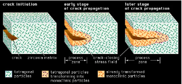
Zirconia ceramics can spontaneously revert the tetragonal phase into monoclinic phase, producing stresses, surface microcracking and lost of structural integrity in a phenomenon known as hydrothermal degradation or low temperature degradation (LTD). The stability of the tetragonal structure can be controlled by three factors: the grain size, the constraint from a surrounding matrix, and the amount of dopant additions. Transformation toughening is a mechanism that can be used to improve the toughness of zirconia by controlling the transformation process in the stress field ahead of the crack tip [7, 8]. What happens during the transformation toughening is that the volume expansion associated with the transformation from the tetragonal to monoclinic phase acts on the crack in such a way as to reduce its potential to propagate (Fig. 1.3) [4, 8].
3
1.5. Processing zirconia
The correct processing of zirconia affects the overall properties and the behavior of this ceramic, being a really important step.
A problem existing with ceramics, zirconia included, is that they exhibit high melting points, so they cannot be easily heated to their melting temperatures to be processed, as it happens with most metals and polymers. Therefore, one alternative route to this problem is the processing of powders to form the ceramic. This process involves the packing together of fine powders, their consolidation and heating to form bonds [8, 10].
The compacting of the zirconia powders will allow obtaining a dense compact material with reduced grain size, to optimize the ceramic mechanical properties [5, 10, 11]. Finally, the compact ceramic is sintered. The conventional sintering in ceramics uses high temperatures and it can be divided in three stages, shown in figure I.5. In the first stage, the powder is already compacted and the particles are in contact with each other but they are not physically bonded (Fig. 1.4 a) [8, 11].
In the second stage the compacted powder is heated to a temperature that is usually about 2/3 of its melting point. At this stage „necks‟ begin to form between the particles, binding them together (Fig. 1.4 b). Finally, the small contact areas between particles expand, and at the same time the density of the compact increases and the total void volume decreases. In the third stage, individual particles can no longer be seen because they are fully bond together leaving residual porosity in the form of closed-off
Figure 1. 3 - Resistance to cracking in transformation-toughened zirconia. In a ceramic composed of tetragonal zirconia dispersed in a zirconia matrix, the stress field advancing ahead of a propagating crack transforms the small tetragonal particles to larger monoclinic particles. The larger particles exert a crack-closing force in the process zone behind the crack tip, effectively resisting propagation of the crack [9].
4
pores that have sufficiently small diameter so as not to have a detrimental effect on the mechanical properties of the final material (Fig. 1.4 c).
The powder particle size will control the final pore size and distribution: the smaller the particle size the smaller the pores and the better the mechanical properties will be [4, 5, 8].
Figure 1. 4 – Zirconia sintering stages. A - Powder particles compacted together; B - Particles beginning to bind together; C- Fully sintered ceramic [8].
1.6. Zirconia Properties
Zirconia is a bioinert ceramic. This property classifies the material according to its reactivity with living tissues, where a bioinert material cannot form a direct bond with natural bone.
Bioinert ceramics are generally corrosion-resistant and wear resistant. They aren‟t significantly toxic, and don‟t induce serious inflammatory, and allergic reactions and also, these ceramics possess common ceramic characteristics such as hardness, low friction coefficient, and resistance to compressive stress [12].
Zirconia is highly biocompatible, has high mechanical strength, fracture toughness, good wear resistance, good resistance to corrosion and to chemicals and aesthetic appearance. However, some of zirconia drawbacks include the fact that it exhibits high density, low hardness, and phase transformations under stress in aqueous conditions, which can degrade their mechanical properties [5, 7]. Some values of mechanical properties of zirconia are shown below, in table 1.1.
5
Table 1. 1-Values of some mechanical properties of Yttria-Polycrystalline Tetragonal Zirconia. Adapted from [4].
Properties Young´s modulus (GPa) Flexural Strength (MPa) Hardness (Vickers, HV0.5) Fracture toughness (MPa/m2) Weibull modulus Density Y-TZP (Yttria- Polycrystalline Tetragonal Zirconia) 210 950 1250 10,5 18 6
Although zirconia presents good mechanical properties, the fact that it is bioinert has prevented its use in the field of biomaterials and clinical devices in a wider way, as its limited use in dental implants. So, it is important to create new approaches that make possible its wider use. The use of bioactive coatings on zirconia substrates can be a good approach to allow a connection with the surrounding tissue in the oral cavity. Next, a technique to product silica bioactive thin films will be described.
6
2. Thin films production
2.1. Sol gel method for Silica Glasses
The sol-gel process is a wet-chemical technique widely used in materials science and ceramic engineering. It allows to produce glasses, ceramics, metals and polymers. This method is an attractive alternative for the synthesis of glasses for many reasons, as its low temperature, simplicity of required equipments, simple operation schemes, relatively low cost, low environmental impact and, of course, the properties of the obtained material [13].
In recent years, sol–gel process has been increasingly employed for the processing of bioactive glasses, including silica glasses.
The sol-gel process for glasses leads to the formation of gels from mixtures of liquid reagents (sols) at room temperatures. It involves several steps: the evolution of inorganic networks, formation of colloidal suspension (Sol) and gelation of the sol to form a network in a continuos liquid phase (Gel). Drying of the obtained gels, even at room temperature, produces glass-like materials called xerogels (xero-dry) [14, 15]. The sol-gel process for silica glass comprises several steps. First, a silicate precursor is mixed with a solvent and a catalyst and stirred for a few hours. This process leads to hydrolysis. The hydrolysis reaction can be catalyzed by acids (acetic acid, nitric acid, etc.) or alkalis (Sodium hydroxide, Ammonium hydroxide, etc.).
In the gelation process the sol transforms into a gel. This step consists in the establishment of bonds between the solution molecules to form a three dimensional network. It is important to stand out that this process is different from the solidification of a mixture, since the solid structure remains completely impregnated with the liquid of the sol [16].
During the aging step the sol-gel derived material expels the liquid phase (solvent) in the process called syneresis [14, 17]. The pore size of the material depends on factors such as time and temperature of the hydrolysis and kind of catalyst used. The average pore diameter is directly related to the shrinkage of the “wet” gels. During the drying process the gel volume decreases even several times (which is the main reason for cracking. After the drying process a glasslike material is obtained – Xerogel [14].
Finally, the material is heat-treated in order to favor further polycondensation and obtain a material with more adequate mechanical properties, lower pores sizes and structural stability via sintering and densification of the material. In the following scheme the general process to obtain a silica glass through Sol-gel technique is presented.
7
2.2. Hybrid silica glasses
Hybrid glasses are obtained by adding organically-modified alcoxides to the sol. These precursors contain organic groups linked to silicon through a non-hydrolysable covalent bond. Hybrid coatings present critical thicknesses over 2 μm, much thicker than inorganic ones and with better mechanical properties. Organic groups affect the physicochemical properties at the pore surfaces, reducing drying stresses and
Syneresis Liquid Percursors Solvent Catalyzator Hydrolysis Aging Gelation Drying Sintering Xerogel Glass
Figure 1. 5 – Summarizing scheme of Sol-gel technique for glass production. Adapted from [14].
8 consequently the risk of cracking of the film. Methyltriethoxisilane (MTES) is one of the organically modified precursors most employed for the introduction of organic methyl groups. The MTES methyl groups act as network modifiers, reducing the connectivity, increasing plasticity and allowing for higher material densification. Therefore, high MTES contents lead to lower film shrinkage after thermal treatment, as well as to a higher film stability. This precursor usually is used together with Tetraethyl orthosilicate (TEOS) [18].
2.3. Advantages of Sol-gel method
There are several advantages of a sol–gel-derived glass over a melt-derived one, such as:
Lower processing temperatures;
The potential of improved purity, required for optimal bioactivity due to low processing temperatures and high silica and low alkali content;
Improved homogeneity;
Wider compositions ranges can be used (up to 90mol% SiO2) while maintaining bioactivity:
Better bioactivity control by changing composition or microstructure;
Structural variation can be produced without compositional changes by controlling hydrolysis and polycondensation reactions during synthesis;
Increased bioactivity;
Interconnected nanometer scale porosity that can be changed to control dissolution kinetics or be impregnated with biologically active phases such as growth factors;
Can be foamed to provide interconnected pores of 10– 200 μm, mimicking the architecture of trabecular bone [16, 19, 20]
2.4. Thin films production
Manufacturing sol–gel derived coatings is a promising application of sol–gel technology, since a variety of coating materials can be applied on various substrates, such as metals, glasses and ceramics, and without expensive equipment. Furthermore, these coatings allow for improvement in the mechanical, thermal, protective, bioactive and electrical properties of the substrate material. Nowadays, many biomaterials are
9 coated with thin films to modify their surface and interface properties and many studies have been carried out in this area [13, 21]
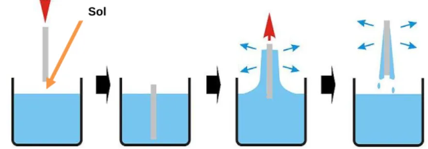
Thin film formation by sol–gel method involves preparation of a sol, deposition of the sol onto a surface, formation of a gel state and drying of the gel. The surface of the substrate is coated, normally by a dip-coating or a spin-coating technique. The resulting film is dried at a temperature near room temperature to preserve the film porosity. Film thickness is determined by the withdrawal speed or spin speed in the case of dip and spin-coating [13, 17, 22]. The following figures (Figure 1.6 and figure 1.7) show the operations schemes of both dip and spin coating, respectively.
2.5. Silica biological properties
The high biocompatibility and the positive biological effects of silica glasses and their reaction products (both leached or formed at the surface) after implantation, have made silica-based glasses one of the most interesting biomaterials during the last 40 years. This type of glasses is bioactive, binds to and interacts with living bone in the body without forming fibrous tissue around it nor promoting excessive inflammation or
Sol
Sol
Figure 1. 6 - Scheme representing the dip-coating process. The stages of the dip coating process represented are: dipping of the substrate into the coating solution, wet layer formation by withdrawing the substrate, gelation and drying of the layer by solvent evaporation [23].
Figure 1. 7 - Scheme representing the spin-coating process. First, there is the deposition of the sol, then the spin-up in the spin coating machine and finally the gelation and drying by solvent evaporation [23].
10 toxicity, provides molecular control over the incorporation and biological behavior of proteins and cells, and provides osteoconductivity and osteointegration [16, 24-26] So, due to the high surface area and porosity derived from the sol–gel process, the range of bioactive compositions is wide, also exhibiting high bone bonding rates together with excellent degradation/ resorption properties [27]. Sol–gel derived glasses also exhibit significant bioresorbability when their pores reach a particular size. Bioresorption is defined as the resorption of a material in vivo, due to the action of osteoclasts, which in this case is enhanced by the interconnected pore network, high surface areas and low particle density. These materials degrade gradually while the biological tissue is formed [20].
A common characteristic of all known bioactive materials is the formation of a biologically active hydroxycarbonated apatite (HCA) layer, due to surface dissolution, in a physiological environment. The higher the solubility of the glass, the more pronounced is the effect on bone tissue growth. In addition, degradation ionic products, especially silica species, have shown osteoconductive properties. This formation of HCA on bioactive glasses and the release of soluble silica and calcium ions to the surrounding tissue are key factors in the rapid bonding of these glasses to tissue, stimulating of tissue growth and application in tissue engineering scaffolds [16, 20, 26]. There are two classes of bioactivity. The silica glasses belong to the Class A bioactive materials. These materials show fast bone bonding, enhanced bone proliferation and, they also bind to soft connective tissues. Class A bioactive materials exhibit 11 reaction stages that lead to enhanced proliferation and differentiation of osteoblasts and recreation of trabecular bone architecture in situ. These are described below. Stages 1-5 are chemical and stages 6-11 are concerned to the biological response:
1. Rapid exchange of Na+ and Ca2+ with H+ or H3O+ from solution (diffusion controlled with t1/2 dependence, causing hydrolysis of the silica groups, which creates silanols);
The pH of the solution increases as a result of H+ ions in the solution being replaced by cations.
2. The cation exchange increases the hydroxyl concentration in solution, which leads to etching of the silica glass network. Soluble silica is lost to the
O
Na
H
O
H
Si
O
H
Na
O
H
Si
a q11 solution as Si(OH)4 resulting from the breaking of Si-O-Si bonds and the
continued formation of Si-OH (silanols) at the glass solution interface:
This stage is an interface-controlled reaction with a t1.0 dependence.
3. Condensation and re-polymerization of a SiO2-rich layer on the surface,
depleted in alkalis and alkali-earth cations.
4. Migration of Ca2+ and PO43- groups to the surface through the SiO2-rich layer,
forming a CaO-P2O5-rich film on top of the SiO2-rich layer, followed by growth
of the amorphous CaO-P2O5 -rich film by incorporation of soluble calcium
and phosphates from solution.
5. Crystallization of the amorphous CaO-P2O5 film by incorporation of OH- and
CO32- anions from solution to form a mixed hydroxyl carbonate apatite (HCA)
layer.
6. Adsorption and desorption of biological growth factors, in the HCA layer (continues throughout the process), to activate differentiation of stem cells. 7. Action of macrophages to remove debris from the site allowing cells to
occupy the space.
8. Attachment of stem cells on the bioactive surface.
9. Differentiation of stem cells to form bone growing cells osteoblasts. 10. Generation of extracellular matrix by the osteoblasts to form bone
11. Crystallization of inorganic calcium phosphate matrix to enclose bone cells in a living composite structure [16, 20, 26].
2.6. Addition of Nanoparticles
Ceramic nanoparticles can be added to the silica thin films in order to increase bioactivity and contact surface area. Hydroxyapatite (HA) has been widely used as a biocompatible ceramic in many areas of medicine, but mainly for contact with bone tissue. HA possesses exceptional biocompatibility, bioactivity and osteoconductive properties with respect to bone cells and tissues, probably due to its similarity with the hard tissues of the body [28, 29].
Compared to conventional ceramic formulations, nanophase HA properties such as surface grain size, pore size, wettability, etc, could control protein interactions (for
Si
O
H
O
H
Si
O
H
Si
O
Si
2
12 example, adsorption, configuration and bioactivity); therefore, modulating subsequent enhanced osteoblast adhesion and long-term functionality. Previous studies discovered that these enhanced osteoblast functions are proliferation, alkaline phosphatase synthesis and calcium containing mineral deposition. Nanometer grain size topography and surface wettability are nanoceramic material properties that not only promote increased selective vitronectin adsorption (a protein that mediates osteoblast adhesion) but also affect conformations that enhance osteoblast functions [28, 30, 31].
13 3. Micropatterning
3.1. Micropatterning Aspects
Topographic modulation of tissue response can be one of the most important considerations during the design and manufacture of a biomaterial. If tissue and cell types differ in their response to topographic variations, this phenomenon may be exploited to design implant materials.
Surface microfabrication techniques have been widely utilized for the spatial control of cells in culture. Many strategies have employed changes in surface charge, hydrophilicity, and topology to regulate cell functions such as attachment. The surface-patterning techniques enabled visualization of the effect of surface properties on cell functionality and spatial control of cellular micro-organization [32, 33].
Among the strategies to modify implant surfaces is micropatterning. This technique, allied to sol-gel method provides promising and cost-effective micropatterning processes. The general aspects of this technique are that an initially liquid/gel is allowed to acquire its final geometry by solidifying in a mold. This technique allows the reproduction of the mold fine details. The molds may have structures with tens of nanometer size features and can be generated in elastic polymers such as polydimethylsiloxane (PDMS).The micropatterning method can be used to produce micropatterns even on curved substrates. Although, it is important that in the molding process the solution covers the surface of the substrate and allows the contact of the elastic stamp with the substrate. The patterning required in microfabrication is usually carried out by photolithography. Although it is difficult to find a better technology, photolithography nonetheless has disadvantages. The size of the features that it can produce is limited by optical diffraction, and the high-energy radiation needed for small features requires complex facilities and technologies. Photolithography is an expensive technique, it cannot be easily applied to non-planar surfaces and it provides almost no control over the chemistry of patterned surfaces, especially when complex organic functional groups of the sorts required in chemistry, biochemistry, and biology are involved [34-36].
3.2. Soft-Lithography
Soft-lithography is a general term for a variety of techniques, all of them employing an elastomeric (PDMS) mold to develop patterns on a planar surface.
14 Micropatterning by soft-lithography as a bench type processing technique is remarkable for its economy and simplicity, as well as for its potential to produce a variety of surface patterns or modifications without the complex masks and steps required in optical lithography. Soft-lithography techniques can be used to develop both two-dimensional surface patterns as thin films or SAMs, as well as to generate quasi three-dimensional topographical features. Soft-lithography can produce micro and nano-features arranged in an organized manner (isotropic) or in a random manner (anisotropic) [33, 36]. A schematic figure of the soft-lithography process is shown bellow in figure 1.8.
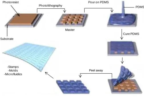
Figure 1. 8 - Soft–Lithography process to obtain a final elastomeric negative mold with the desired pattern. Adapted from [37].
In soft-lithography, a master with the desired features is first prepared by photolithography. The micropatterned PDMS mold is then prepared by casting a liquid pre-polymeric mixture on a wafer master containing the designed pattern. The mixture is left curing, and finally the PDMS is peeled off the master to obtain the finished negative mold [33].
After preparation the PDMS mold is used to stamp a solution on a chosen substrate. Associated with the sol-gel method, two techniques to microstamp a substrate are highlighted: microtransfer molding (μTm) and micromolding in capillaries (MIMIC) [35, 36]. A schematic figure of the method of processing of these techniques is shown bellow (Fig. 1.9) Photoresist Substrate Photolithography Pour on PDMS Master Peel away Cure PDMS PDMS -Stamps -Molds -Microfluidics
15
Figure 1. 9 - Two microstamping techniques associating soft-lithography and solutions prepared by sol-gel method. a) Microtransfer molding and b) Micromolding in capillaries. Adapted from [38].
In the micro-transfer molding technique (Fig. 1.9 a), a small amount of the sol-gel solution is deposited onto the patterned surface of the PDMS mold so it fills the relief. After removing any excess of sol-gel solution, the filled mold is placed in contact with the substrate, and following curing, the PDMS mold is removed leaving a deposited pattern of the sol-gel. By using this technique, isolated features can be generated on the substrate. In what concerns to the micromolding in capillaries, the clean PDMS mold is first sealed against the glass surface. The sol-gel solution is then deposited at the open ends of the PDMS mold, and capillary action allows infiltration of the sol-gel solution into the micro channel patterns. After in situ curing and removal of the PDMS mold, the patterned structure remains on the surface (Fig. 1.9 b) [35, 36].
3.3. Cell behavior
The structural organization of tissues plays a major part in deciding the degree and direction of tissue growth and cell movement: an effect often termed ‘contact guidance’. Various studies have indicated that it may be possible to design the surface texture of implanted materials to improve the performance of an implant [33].
Biocompatibility of soft-tissue implants is often hampered by the development of capsules that eventually might contrast and impair implant function. It has been shown that capsule formation can be significantly reduced by using materials with textured
a b
Liquid sol-gel solution PDMS
stamp
Invert stamp; bring into contact with substrate
Substrate
Peel away PDMS stamp
Substrate
Add liquid sol-gel solution Liquid sol-gel solution
Remove PDMS channels
16 surface elements in the micron and nano range [32, 33]. Topographic modulation of tissue response can be one of the most important considerations during the design and manufacture of a biomaterial [32]. There are several approaches using patterned surfaces that show improved cellular activity and enhancement of extracellular matrix synthesis of adherent cells, providing a faster and more reliable osteointegration response [39-41]. There is clear evidence that cell adhesion, proliferation, organization and phenotype are modulated at the micro-scale [42]. These effects arise from the increased adhesion of connective tissue cells onto the roughened surfaces, resulting in closer tissue apposition onto to the implant. Recent advances have shown that we are only in the beginning of understanding the importance of controlled cellular microenvironments and that the application of microfabrication approaches to study cell biology has opened up many and new interesting avenues for research [43].
The following figure shows the effect of nanotopography in cell behavior.
Figure 1. 10 - Depiction of broad range of nanoscale topography effects observed in cellular and protein adsorption. Both cell specificity and extent of cell adhesion are altered. Depending on the nano-architecture cell spreading may be increased or decreased. By presently undefined mechanisms, cell proliferation appears to be enhanced by nanoscale topography [33].
17
4. Mesenchymal Stem Cells and Bone Remodeling
4.1. Mesenchymal Stem Cells
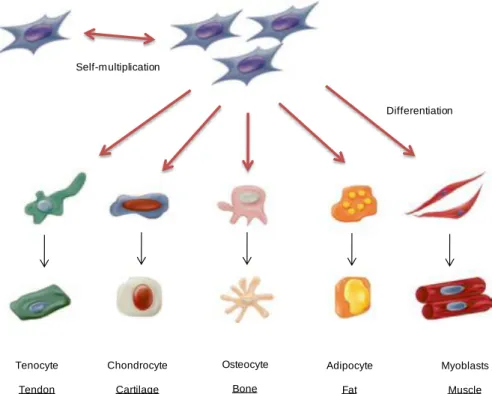
Mesenchymal Stem Cells (MSCs) are a heterogeneous group of progenitor cells with pluripotent capacity to differentiate into several connective tissue cell types, including osteoblasts, chondrocytes, adipocytes, tenocytes and myocytes (figure 1.11) [44, 45]. MSCs were first identified in bone marrow but since then they have been isolated and identified in many other tissues including adipose tissue, umbilical cord blood, muscle, dental pulp, amniotic fluid and skin [46, 47].
Figure 1. 11 - Multilineage differentiation potential of mesenchymal stem cells (MSCs). Adapted from [48].
The isolation of MSCs from these various tissues usually involves adherence of the cells to tissue culture plastic, with or without subfractionation or enrichment strategies. The three main criteria to identify a MSC population are the adherence to tissue culture plastic under standard culture conditions, cell surface characterization by cell surface antigens and in vitro tri-lineage mesoderm differentiation [47, 48].
Human MSCs have been defined by the positive expression of the cell surface antigens including CD73, CD90, CD105 and a lack of expression of hematopoietic antigens including CD11b or CD14, CD34, CD45, CD79 or CD19, and HLA-DR [48]. Under appropriate conditions, MSCs are able to differentiate into cell types of different lineages, in vitro. For example, incubating MSCs with ascorbic acid,
beta-Tenocyte Tendon Chondrocyte Cartilage Osteocyte Bone Adipocyte Fat Myoblasts Muscle Self-multiplication Differentiation
18 glycerophosphate and dexamethasone for 2-3 weeks induces osteogenic differentiation [45]. After this time of culture, bone cells can easily be identified.
The morphological and histological criteria by which osteoblastic cells, including osteoprogenitors, pre-osteoblasts, osteoblasts, and lining cells or osteocytes, are identified have been reviewed extensively. Morphological definitions are now routinely supplemented by the analysis of the expression of cell- and tissue-specific macromolecules, including the ecto-enzyme ALP, bone matrix proteins like type I collagen (COLL-I), osteocalcin (OCN), OPN, and bone sialoprotein (BSP) and transcription factors that regulate them and the differentiation events (Runx2, AP-1 family members, Msx-2, Dlx-5, etc.) [47].
4.2. Dental Pulp Stem Cells
Dental Pulp Stem Cells are one type of mesenchymal stem cells that can be obtained from the dental pulp, a soft connective tissue entrapped within the dental crown that is an extremely rich site for stem cell collection. In addition to nerves and blood vessels, the pulp contains highly proliferative stem cells possessing a self-renewal and differentiation capability. Owing to its peculiar formation, the pulp chamber is a sort of „„sealed niche‟‟ and may explain why it is possible to find a rather large number of stem cell there (figure 1.12) [49-51].
During the sixth week of embryogenesis, the ectoderm covering the stomodeum begins to proliferate, giving rise to the dental laminae. Ectoderm–mesoderm interactions then lead to placode formation. One of these ovoidal ectodermal structures develops into tooth germs, where neural crest cells differentiate into the dental organ, dental papilla and dental follicle. Therefore, dental pulp is made of both ectodermic and mesenchymal components, containing neural crest cells that display plasticity and multipotential capability [49].
A series of studies have shown that DPSC provide characteristic stem cell properties as they are self-renewed, highly proliferative with clonogenic efficiency, and possess the capability for multi-lineage differentiation [50].
This type of stem cells was first isolated by Gronthos and colleagues, in 2000. Since then, they have been studied for several favorable reasons, such as easy surgical access, the high efficiency of the extraction procedure of the stem cells from the pulp tissue, their differentiation ability and proved interactivity with biomaterials for tissue engineering [51].
In 2005, the group of Laino and Papaccio isolated a selected population of dental pulp stem cells called SBP-DPSCs, which were already capable of woven bone tissue
19 formation in vitro. Experiments performed with SBP-DPSCs confirmed that bone was the main commitment of dental pulp stem cells, from the expression RUNX-2, a transcription factor involved in the inducing of osteoblast differentiation. Laino and colleagues also demonstrated that this type of cells, when undergo their differentiation to preosteoblasts, deposit an extracellular matrix which becomes a calcified woven bone tissue called LAB (living autologous bone) that can be produced already in vitro, in 3D scaffolds. Upon transplantation in vivo, the tissue is actually remodeled to form a lamellar bone through co-differentiation of SBP-DPSC into osteoblasts and endotheliocytes. During the in vitro ossification process, the SBP-DPSCs cells give rise to both osteoblasts and endotheliocytes, and to bone containing vessels, leading to the formation of an adult bone tissue after in vivo transplantation. The presence of these vessels and their complete integration with host, other than being the demonstration of a complete tissue growth from stem cells, is of great importance for its use in therapy [51, 52].
Due to their high proliferation rate and efficiency in producing bone chips, DPSCs seem to be the best candidates to study bone formation with respect to bone marrow stem cells (BMSCs), whose efficiency is limited by the fact that they differentiate into osteoblasts and produce small calcified nodule, but not chips of bone tissue. In this way in pre-clinical phase it is possible to assess the osteoconductivity of a biomaterial [51].
20
4.3. Bone Remodeling
Bone contains four types of cells: osteoprogenitor cells, osteoblasts, osteocytes, and osteoclasts, of which osteocytes are the most abundant. In general osteoblasts are cells that create new bone, and osteoclasts are cells that destroy it when force is applied [54, 55].
Understanding the process of bone remodeling is of paramount importance in implant design and materials selection [4]. Bone is first resorbed by osteoclasts and then formed at the same site by osteoblasts. These cells form the basic metabolic unit (BMU) that reconstructs bone. Bone modeling and remodeling achieve strength for loading and lightness for mobility in two ways: by strategically depositing bone in locations where it is needed to modify bone size and shape, and by removing bone from where it is not needed to avoid bulk [56, 47]. Bone remodeling can be separated into two categories; surface and internal remodeling. Surface remodeling is the resorption and deposition of bone material on the external surfaces of bone (periosteal surfaces), while internal remodeling is reinforcement and resorption in the endosteal surfaces, resulting in changes in the bulk density of the bone [4, 56].
Bone remodeling involves four main processes: activation, resorption, reversal and formation. The remodeling cycle is initiated by the activation of the quiescent bone surface, which is covered with bone lining cells. Osteoclast precursor cells are recruited to the activated surface and fuse to form mature, bone resorbing osteoclasts. The osteoclasts attach to the surface and dissolve the inorganic matrix by creating an acidic microenvironment and degrade the organic matrix with specific enzymes. As bone resorption subsides and resorption pits remain osteoclasts disappear and mononuclear cells prepare the surface for bone formation. Also, osteoclasts phagocytose osteocytes and this may be one way the signal for resorption is removed. Products from the osteoclasts independent of their resorption activity, and products from the resorbed matrix partly regulate osteoblastogenesis and bone formation. The bone remodeling cycle is finished with the synthesis and deposition of bone matrix by osteoblasts, where some differentiate to bone lining cells building a canopy covering the surface keeping the material dormant until the next cycle and others become entombed in the bone matrix and become osteocytes [55, 57].
21
22
5. Oral Infections
5.1. InfectionsThe implantation of a biomaterial into the human body, and the subsequent damage caused to the tissues is known to increase susceptibility to infection [59]. Nowadays, device-related bacterial infections are one of the greatest challenges to the more widespread application of medical implants [60]. Microbial adhesion to surfaces and the formation of a complex biofilm at the interface between a biomaterial and the biological environment are frequent reasons for the failure of biomaterial devices [59].
Infection represents one of many factors contributing to the failure of dental implants. The oral cavity is a unique environment, as different types of surfaces (hard, soft, natural and artificial) share the same ecological niche. In order to survive within this „open growth system‟ and to withstand shear forces, bacteria need to adhere either to soft or to hard tissues. The initial adhesion and the successful colonization of bacteria onto solid surfaces play a key role in biofilm formation and in the pathogenesis of infections related to biomaterials [61, 62].
Clearly, controlling this initial adhesion into a biofilm depends mainly on the surface properties. While several dental materials promote selective adherence during early dental biofilm formation, other modified biomaterials may provide resistance to bacterial adhesion and biofilm formation [62].
A biofilm is a layer-like aggregate of cells and cellular products attached to a solid surface or substratum. An established biofilm structure is made up of microbial cells and extracellular polymeric substances and provides an environment for the exchange of genetic material between cells. Within biofilms, microorganisms organize communities with structural and functional heterogeneity similar to that of a multicellular organism; interstitial voids between micro-colonies can be considered to serve as a rudimentary circulatory system. Cell-to-cell signaling (i.e. quorum-sensing) induces biofilm microorganisms to change patterns of gene expression. Quorum-sensing is the ability of a bacterial colony to sense its size and in response to regulate its activity. At a certain population density, intercellular signals activate genes involved in biofilm differentiation [63]. The next figure (Fig.1.14) shows the processes to a biofilm formation.
23
Figure 1. 14 - Diagram showing the development of a biofilm as a five-stage process where, stage 1: initial attachment of cells to the surface. Stage 2: production of extracellular polymeric substance. Stage 3: early development of biofilm architecture (colonization). Stage 4: maturation of biofilm architecture. Stage 5: dispersion of single cells from the biofilm. In the final stage, when environmental conditions become unfavorable, some of the bacteria may detach and swim away to find a surface in a more favorable environment [63].
5.2. Bacteria causing the infection
Although the mechanism of bacterial infections with implants is not well understood, the microflora around dental implants appear to be similar to that found around natural teeth. So, microbial pathogens associated with periodontitis may also contribute to implant failure [64].
Between the main microorganisms present in oral cavity, usually related to various infections, are Porphyromonas gingivalis and Streptococci mutans. Along the years, various studies have shown presence of these two bacteria in infected dental implants, although there is not much information about these interactions [65, 66].
Porphyromonas gingivalis is a gram-negative anaerobic that is widely recognized as a predominant contributor to human periodontitis. This is a polymicrobial infection-driven inflammatory disease of the oral cavity, characterized by chronicity and destruction of the tooth-supporting tissues [67]. In dental implants is normally associated with peri-implantitis [68].
When peri-implantitis is prolonged, the alveolar bone that supports the implant may be degraded and the implant fails. When this happens it becomes very difficult to replace the implant. Figure 1.15 shows a comparison between a healthy tooth and one with a periodontal disease.
24
Figure 1. 15 - Comparison between a healthy tooth and a tooth with peridontal disease [69].
P. gingivalis is thought to spread through tissue, destroy it, and evade host defenses by the use of secreted cell-bound proteases, immunoactive cellular compounds, and toxins. P. gingivalis cytotoxic metabolic end products, which include butyrate, propionate, have low molecular weights which allows them to easily penetrate periodontal tissue and disrupt the host cell activity [70].
Other bacteria commonly associated with dental infections are Streptococcus mutans. Previous studies have indicated that Streptococci mutans are the predominant colonizing micro-organisms of oral surfaces. S. mutans is considered to be a most important etiological agent of diseases associated with dental caries. On teeth, it is one of the species that form biofilm causing dissolution of enamel by acid end-products resulting from carbohydrate metabolism [62]. Streptococcus mutans is a Gram-positive bacterium that metabolizes different kinds of carbohydrates, creating acidic environment in the mouth as a result of this process. This acidic environment in the mouth is what causes the tooth decay. Associated with implants, it is thought that this bacterium can create an acidic environment that degrades the implant surface, provoking corrosion of the implant surface, although not much is known about this biological interaction [66, 71].
25
II. Materials and Methods
1
. Materials Preparation
1.1. Silica preparation
Zirconia discs were prepared using a centrifuge assisted casting method; however it was very difficult to reproduce the coatings in the zirconia surface in large scale. So, since a high number of samples was required to perform all the characterization tests in the thin films, another material that would allow higher reproducibility (glass) was used as substrate. This way, in this study glass coverslips with 15 mm diameter were used as substrates to evaluate the silica flat and micropatterned thin films.
Hybrid silica sols were produced via sol-gel process with acid catalysis in a single stage. Tetraethylorthosilicate (TEOS, Sigma-Aldrich) and Methyltriethoxisilane (MTES, Sigma-Aldrich) were used as silica sols precursors in a ratio of 40:60, respectively. Alcohol was used as a solvent and acetic and nitric acids were used as catalysts. The flat SiO2 coatings were applied on glass cover slips by spin-coating for 45s at
3000rpm.
1.2. Molds preparation
Soft-lithography was used to produce the molds with the microscale features by a two-step process. First, photolithography was used to produce master pattern with micro-scale dimensions. The master was then used to create polydimethylsiloxane (PDMS) negative molds. PDMS (Silastic T-2, Dow Corning, USA) was uniformly mixed with a curing agent, deposit into the master, degassed and cured. The final negative molds were then used to stamp the samples and create the micropattern. Figure 2.1 shows the complete soft-lithography process since the wafer production to the stamping step.
26
Figure 2. 1 – Soft-lithography method used to create micropatterned PDMS molds.
1.3. Microstamping
Three types of microfabricated silica thin films were produced. Nanoscale hydroxyapatite (nanoHA) particles were introduced into the sol for incorporation into the thin films at two difference weight ratios (1 and 5%) and the silica sol was also used solo. The microfabricated coatings were obtained by single molding (Figure 2.2) by applying 40 μl of the silica mixtures in the glass coverslips and pressing with the PDMS mold after. This was left drying overnight and after the PDMS mold was removed, as shown in figure 2.2.
Figure 2. 2 – Stamping procedure by single molding method. 1.4. Sintering
Samples were sintered at 500ºC for 60 minutes, using the sintering cycle shown in figure 2.3.
27
Figure 2. 3 – Sintering cycle used to sinter the silica thin films.
2. Surface characterization
After the heat-treatment, the samples were evaluated under light microscopy and the surface was characterized.
2.1. Scanning Electron Microscopy / Energy Dispersive X-ray Spectroscopy
Scanning Electron Microscopy (SEM) and Energy Dispersive X-ray Spectroscopy (EDS) evaluations were carried out with a FEI Quanta 400FEG ESEM / EDAX Genesis X4M scanning electron microscope at 15KeV. The samples were sputter-coated with palladium-gold.
2.2. Contact Angle
The contact angle measurements were performed using equipment from Data physics Instruments GmbH, Germany, model OCA 15 with a video device camera, an electronic syringe unit (Hamilton) and a SCA 20 software. The sessile drop method was used with ultrapure water at 25ºC in a chamber saturated with the same liquid. The contact angle was calculated by the Laplace-Young function when the drop contacted with the material surface. Since three of the materials have patterns, all were similarly oriented in order to maintain the same conditions to all the samples during all the experiment. The results expressed are the arithmetic mean ± standard deviation.
Room temp Room temp 5ºC/min 110ºC 5ºC/min 5ºC/min 30 min 30 min 60 min 200ºC 500ºC
![Figure 1. 1 – Temperatures in the three phases of Zirconia [4].](https://thumb-eu.123doks.com/thumbv2/123dok_br/15722150.1070600/18.892.366.537.721.905/figure-temperatures-phases-zirconia.webp)
![Figure 1.2 - Structure of the three phases of Zirconia [5].](https://thumb-eu.123doks.com/thumbv2/123dok_br/15722150.1070600/19.892.209.684.181.382/figure-structure-phases-zirconia.webp)
![Figure 1. 4 – Zirconia sintering stages. A - Powder particles compacted together; B - Particles beginning to bind together; C- Fully sintered ceramic [8]](https://thumb-eu.123doks.com/thumbv2/123dok_br/15722150.1070600/21.892.222.670.257.605/figure-zirconia-sintering-particles-compacted-particles-beginning-sintered.webp)
![Figure 1. 5 – Summarizing scheme of Sol-gel technique for glass production. Adapted from [14]](https://thumb-eu.123doks.com/thumbv2/123dok_br/15722150.1070600/24.892.183.601.111.846/figure-summarizing-scheme-sol-technique-glass-production-adapted.webp)

![Figure 1. 12 - Collection site of dental pulp stem cells from the dental pulp [53].](https://thumb-eu.123doks.com/thumbv2/123dok_br/15722150.1070600/36.892.250.700.698.1026/figure-collection-site-dental-pulp-stem-cells-dental.webp)
