F
ACULDADE DEE
NGENHARIA DAU
NIVERSIDADE DOP
ORTODesign Optimization of Stand-Alone
Hybrid Energy Systems
Francisco Gonçalves Goiana Mesquita
A Dissertation submitted under the scope of
Mestrado Integrado em Engenharia Electrotécnica e de Computadores Major Energia
Supervisor: Professor Doutor Cláudio Domingos Martins Monteiro
Abstract
Millions of people worldwide do not have access to electricity for the most basic goods of survival. Millions of people do not have access to culture – the pleasure of reading a book because they do not have the luxury of illumination during the night.
One of the many ways to extinguish this unevenness between the developed and underdevel-oped world starts from using renewable resources as a source of energy. Independently of the world´s site where we stand, these sources are abundantly, free and inexhaustible. The problem inhabits in the way as this renewable resources are managed in function of a certain associated load demand.
Hybrid energy systems, namely the stand-alone or isolates ones, show an enormous weight in the path for adopting ways of giving access to energy in the most remote places of our planet. To conjugate, in an optimized way, the different forms of energy – wind, water and sun – is the course we have to adopt and implement so that motivated investors can apply their monetary resources in underdeveloped countries such as African countries.
This was the context on which this thesis was based, aimed to develop capable tools to optimize the design of stand-alone hybrid systems, concretely applied to any type of resource data and load information. However, the complexity of this problem is of an extremely high mathematical degree. Unlike the algorithms already developed, the objective was to develop a tool that could optimize continuous variables, in this case, the wind, hydro and solar resources, as well as the batteries and the diesel generator that constitute a generic hybrid system.
An innovator and powerful optimization tool was then developed – GraSO (Gradient Swarm Optimization Algorithm) – capable of efficiently answer to this kind of problems. This software is skilled at the point that it can optimized both operation (load following and cycle charging dispatch strategies) and design of the hybrid system.
This algorithm was tested in several standard evaluation functions and presented satisfactory results. Hence, his application in other kind of problems is possible and advised.
With the developed algorithm core, GraSO was then applied to the system model created in an Excel spreadsheet proving his reliability to optimize the design of stand-alone hybrid energy systems.
keywords:
Design, GraSO, Hybrid Energy Systems, Metaheuristics, Operation, Optimization Algo-rithms, Stand-Alone
Acknowledgments
To my Parents To my Brother To my Friends To You, Ana.
Thanks Boss! See you around!
Francisco Mesquita
“We invent to persuade ourselves that events are knowable and that life has order and direction”
Calvin & Hobbes
Contents
1 Introduction 1 1.1 Context . . . 1 1.2 Motivation . . . 2 1.3 Objectives . . . 3 1.4 Methodologies . . . 3 1.5 Thesis Structure . . . 31.6 Data and Information . . . 4
2 Hybrid Energy Systems - Principles 5 2.1 Introduction . . . 5
2.2 Applications . . . 5
2.3 Technology used . . . 7
2.3.1 Renewable Energy Generators . . . 7
2.3.2 Fossil Fuel Generators . . . 8
2.3.3 Energy Storage . . . 8
2.3.4 Power Converters . . . 11
2.3.5 Supervisory Controller . . . 12
2.4 Energy Loads . . . 13
2.5 Renewable Energy Resources . . . 13
2.5.1 Wind . . . 13
2.5.2 Solar Radiation . . . 14
2.5.3 Hydropower . . . 14
2.6 Economics . . . 14
3 Hybrid Energy Systems - Design Considerations 15 3.1 Introduction . . . 15
3.2 Brief Review on Design Techniques . . . 15
3.3 Software . . . 23 3.3.1 HOMER . . . 23 3.3.2 HYBRID 2 . . . 25 3.3.3 HOGA . . . 25 4 System Modeling 27 4.1 Introduction . . . 27
4.2 Wind Turbine Model . . . 27
4.2.1 Investment Costs . . . 28
4.3 Photovoltaic Performance Model . . . 30
4.3.1 Investment Costs . . . 31
viii CONTENTS
4.4 Hydro Generator Model . . . 33
4.4.1 Investment Costs . . . 34 4.5 Diesel Generator . . . 35 4.5.1 Investment costs . . . 36 4.6 Storage . . . 38 4.6.1 Investment Costs . . . 40 4.7 Load Diagram . . . 41 4.8 Dispatch Strategies . . . 41 4.8.1 Load Following . . . 41 4.8.2 Cycle Charging . . . 42 4.8.3 Other Strategies . . . 44 4.8.4 Final Model . . . 48
5 GraSO - A Novel Optimization Technique 49 5.1 Introduction . . . 49 5.2 Motivation . . . 49 5.3 Concept . . . 50 5.4 Algorithm Description . . . 50 5.5 Test Functions . . . 57 5.5.1 Sphere Function . . . 57 5.5.2 Schaffer´s Function . . . 58 5.5.3 An ELD problem . . . 60
6 The GraSO approach to the Design Optimization of Hybrid Energy Systems 63 6.1 Introduction . . . 63
6.2 Objective Function . . . 63
6.3 Constraints . . . 64
6.4 Developed Software . . . 64
6.5 Case Studies . . . 66
6.5.1 Assuming Different Investment Costs . . . 66
6.5.2 Assuming Equal Investment Costs . . . 66
6.6 Critical Analysis . . . 76
7 Conclusions 81 7.1 Final Conclusions . . . 81
7.2 Future Works . . . 82
A Sphere´s Iteration Process 83
List of Figures
2.1 Schematic of a typical wind diesel hybrid system with storageCorbus(2006) . . 6
2.2 Possible devices and arrangements in HESManwell(2004) . . . 7
2.3 A typical diesel engine fuel curveFarret(2006a) . . . 9
2.4 Energy storage devices and corresponding time capacityFarret(2006b) . . . 10
2.5 Supervisory control functionsManwell(2004) . . . 13
3.1 Power supply options for village electrificationGupta et al.(2008a) . . . 18
3.2 Flow-chart of a linear programming method including a Delphi study Iniyan e Sumathy(2003) . . . 19
3.3 Data sources of the expert systemMorea et al.(2007) . . . 20
3.4 Flowchart of the genetic optimization methodologyKoutroulis et al.(2006) . . . 21
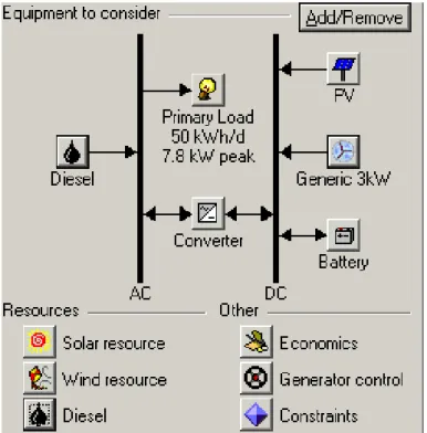
3.5 Schematic of a PV-wind-diesel system with HOMERkn:(2005) . . . 23
4.1 One year output power from a 1kW wind turbine . . . 29
4.2 Modeling of a 100 kW wind generator . . . 29
4.3 Cost per installed kilowatt of wind generating power . . . 30
4.4 One year photovoltaic power output profile (kW) . . . 31
4.5 Cost per installed kilowatt of photovoltaic generating power . . . 32
4.6 One year hydro power output profile (kW) . . . 33
4.7 Cost per installed kilowatt of hydro generating power . . . 34
4.8 Fuel consumption of a 150 kW DG . . . 36
4.9 Levelised cost of operation of a 150kW DG . . . 37
4.10 Diesel generator investment cost curve (eper kilowatt) . . . 37
4.11 Battery discharge cycles and corresponding depth of discharge . . . 39
4.12 Total life energy and equivalent depth of discharge . . . 39
4.13 Battery cost versus capacity . . . 40
4.14 Sample load diagrams . . . 41
4.15 Load following Algorithm flow-chart . . . 43
4.16 Load following dispatch for 48 hours . . . 44
4.17 Cycle charging flowchart - part I - batteries . . . 45
4.18 Cycle charging flowchart - part II - diesel generator . . . 46
4.19 Cycle charging flowchart - part III - excess and unmet load . . . 47
4.20 Cycle charging dispatch for 48 hours . . . 47
5.1 GraSO Flowchart . . . 51
5.2 Evaluation of the ϕ parameter in distant optimal solutions situations . . . 53
5.3 Evaluation of the ϕ parameter in near optimal solutions situations . . . 53
5.4 Particle swarm behavior near the optimal solution . . . 55
5.5 Particle swarm behavior distant from the optimal solution . . . 56
x LIST OF FIGURES
5.6 Inverted sigmoid activation functions behavior . . . 57
5.7 De Jong’s function 1 - sphere . . . 57
5.8 Sphere’s fitness function convergence in R30 . . . 58
5.9 Schaffer´s convergence with GraSO . . . 59
5.10 Schaffer’s function . . . 59
5.11 Studied single-bus systemMiranda(2009) . . . 60
5.12 Comparative analysis of using GraSO in an economic load dispatch problem . . . 61
6.1 Levelized cost of energy minimization block diagram . . . 65
6.2 Monthly output power assuming different technology investment costs . . . 66
6.3 LCOE convergence . . . 67
6.4 External parameters convergence . . . 67
6.5 Variance oscillation until convergence . . . 68
6.6 Load sample 1 . . . 68
6.7 Monthly energy production with a load following strategy for load diagram 1 . . 69
6.8 Monthly energy production with a cycle charging strategy for load diagram 1 . . 70
6.9 Load sample 2 . . . 71
6.10 Monthly energy production with a load following strategy for load diagram 2 . . 72
6.11 Monthly energy production with a cycle charging strategy for load diagram 2 . . 73
6.12 Load sample 3 . . . 74
6.13 Monthly energy production with a load following strategy for load diagram 3 . . 75
6.14 Monthly energy production with a cycle charging strategy for load diagram 3 . . 75
6.15 Load sample 4 . . . 77
6.16 Monthly energy production with a load following strategy for load diagram 4 . . 77
6.17 Monthly energy production with a cycle charging strategy for load diagram 4 . . 79
A.1 Graso´s Sphere optimization - Iterations 1 and 2 . . . 84
A.2 GraSO’s Sphere optimization - Iterations 3 and 4 . . . 85
A.3 GraSO’s Sphere optimization - Iterations 5 and 6 . . . 86
A.4 GraSO’s Sphere optimization - Iterations 7 and 8 . . . 87
A.5 GraSO’s Sphere optimization - Iterations 9 and 10 . . . 88
A.6 GraSO’s Sphere optimization - Iterations 11 and 12 . . . 89
A.7 GraSO’s Sphere optimization - Iterations 13 and 14 . . . 90
A.8 GraSO’s Sphere optimization - Iterations 15 and 16 . . . 91
A.9 GraSO’s Sphere optimization - Iterations 17 and 18 . . . 92
List of Tables
3.1 Amount of a site resource typically needed for feasibilityGupta et al.(2008a) . . 18
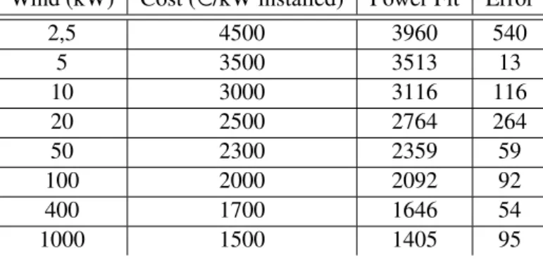
4.1 Wind generator’s investment costs (eper installed kW) and respective fit curve with an average error ε= 154 . . . 29
4.2 Photovoltaic generator’s investment costs (eper installed kW) and respective fit curve with an average error ε=80 . . . 32
4.3 Hydro generator’s investment costs (eper installed kW) and respective fit curve with an average error ε= 133 . . . 34
5.1 Performance evaluation parameters - Sphere function . . . 58
5.2 Performance evaluation parameters - Schaffer’s function . . . 60
5.3 Generator´s cost curve parameters and output power limits . . . 60
6.1 Unit sizing for load diagram 1 with a load following dispatch strategy . . . 69
6.2 Unit sizing for load diagram 1 with a cycle charging dispatch strategy . . . 70
6.3 Unit sizing for load diagram 2 with a load following dispatch strategy . . . 72
6.4 Unit sizing for load diagram 2 with a cycle charging dispatch strategy . . . 72
6.5 Unit sizing for load diagram 3 with a load following dispatch strategy . . . 76
6.6 Unit sizing for load diagram 3 with a cycle charging dispatch strategy . . . 78
6.7 Unit sizing for load diagram 4 with a load following dispatch strategy . . . 78
6.8 Unit sizing for load diagram 4 with a cycle charging dispatch strategy . . . 79
6.9 Case studies LCOE results (e/kWhr . . . 79
Abbreviations and Symbols
List of Abbreviations
AC Alternate Current BES Biomass Energy System BTU British Thermal Unit
CAES Compressed air energy storage CC Cycle Charging
CGHS Central Grid Connect Hybrid System DC Direct Current
DG Diesel Generator DOD Depth of Discharge
EFCE Equivalent Full Cycles of Energy EL Excess Load
EPSO Evolutionary Self-Adaptive Particle Swarm Optimization FEUP Faculdade de Engenharia da Universidade do Porto FPMRT Full Power Minimum Run Time
GRASO Gradient Swarm Optimization HES Hybrid Energy System HGS Hybrid Generation System
HSWSO Hybrid Solar-Wind System Optimization IGBT Insulated Gate Bipolar Transistor
IGHS Isolated Grid Hybrid System
ISEL Instituto Superior de Engenharia de Lisboa ISHS Isolated or Special Purpose Hybrid System LCO Levelized Cost of Operation
LCOE Levelized Cost of Energy LF Load Following
LLP Loss of Load Probability LPS Loss of Power Supply
LPSP Loss of Power Supply Probability MPPT Maximum Power Point tracking NL Net Load
NOCT Nominal Operating Cell Temperature NPC Net Present Cost
NREL National Renewable Energy Laboratory OC Operation Cost
PV Photovoltaic
REN Rede Energética Nacional
xiv Abbreviations and Symbols
SCR Silicon Controlled Rectifier SHP Small Hydro Power
SMES Compressed Air Energy Storage SOC State of Charge
SPV Solar Photovoltaic TC Cells´s Temperature TES Thermal Energy Storage UL Unmet Load
UREDA Uttaranchal Renewable Energy Development Agency VA Volt-Ampere
WES Wind Energy System
List of Symbols
A Incremental diesel fuel consumption rate Ah Ampere hour
Apanel Photovoltaic panel´s area
B Diesel generator fuel consumption at no load Bf Battery flow (dis)charge rate
Bf max Maximum battery flow (dis)charge rate
CD Diesel generator investment cost
Cdiesel Diesel cost
CP Photovoltaic generator investment cost
CH Hydro generator investment cost
CW Wind generator investment cost
Fs1 Inverted sigmoid activation function 1
Fs2 Inverted sigmoid activation function 2
h Height hr Hour
ht Irradiation in a 30º tilt plan
i Discount rate it Number of iterations kW Kilowatt
Lc Critical load
LCOD Diesel generator levelized cost of operation
maxit Maximum number of iterations
Nbat Number of batteries
NBAT max Maximum number of batteries
NBAT min Minimum number of batteries
nswarm Number of particles that constitute the swarm
OCDh Diesel generator operation cost at hour h
PD Diesel generator electrical power outputh
Pgmax Maximum diesel generator power output
PGmax Maximum renewable generator power output
PGmin Minimum renewable generator power output
PHG Hydro generator output power
PPV Photovoltaic generator output power
Abbreviations and Symbols xv
PR Renewable output power
PW G Wind generator output power
R2swarm Particle swarm coefficient of determination R2ϕ ϕ coefficient of determination
SOCmax Maximum state of charge
SOCmin Minimum state of charge
Tamb Ambient temperature
Tf Power failure time
Un Battery nominal voltage
v Wind speed at height h v0 Wind speed at height h0
Vc Cut-in speed
Vf Cut-off wind speed
Vr Rated wind speed
Xqueen Swarm queen
Xbest Best fitness particle
Xswarm Swarm particle
α Scale parameter internal to the algorithm ∆ϕ Normalized variation of ϕ
ε Fit curve mean error
ηpanel panel´s efficiency , adjusted to ambient temperature
ηMPPT Maximum power point tracker efficiency
N (µ,σ2) Gaussian distribution
µ Mean value ∇ϕ ϕ gradient
σ2 Gaussian distribution variance
σFitness Fitness standard deviation for all composing swarm particles
σϕ Distance’s standard deviation between Xqueenand Xswarm
τ Power variation´s coefficient at panel´s cell temperature τP Photovoltaic generator annualized discount rate
τW Wind generator annualized discount rate
τH Hydro generator annualized discount rate
τD Diesel generator annualized discount rate
τB Battery annualized discount rate
Chapter 1
Introduction
This thesis was accomplished as the final scope procedure of Mestrado Integrado em Engen-haria Electrotécnica e de Computadores, Faculdade de EngenEngen-haria da Universidade do Porto.
The aim of this work is to optimize the design of stand-alone hybrid systems, for any place around the world. New and powerful optimization techniques were developed working extremely well when applied to the system optimization. Moreover, this technique shows a great potential when applied in other areas then the one studied here.
This chapter contemplates an initial approach to the problem including the context as well. It presents the basic ideas that will be applied in the dissertation. The chapter’s final exposes an organized abbreviated description and explication of this work.
1.1
Context
Our civilization has steadily progressed due to the energy provided from the three great fossil fuels - coal, petroleum and natural gas. The world as we know it relies on petroleum on a day to day basics for transportation, agriculture, chemicals and materials and, not trivially, for the basic needs of electricity supply. The continues extracting rates mistreat is obviously an unsustainable situation due to the fact that they grossly exceed the rate at which they are laid downDell e Rand
(2004).
Around two billion people world-wide do not have access to electricity services, of which the main share in rural areas in developing countries. Millions of people have hopeless dreams of a fuel source for cooking their food. It is a fact that electricity and general appliances in-crease the quality of life for each one of us, but in ways that we, in developed countries, take for granted. In other words, electricity is an everyday reality but for two-thirds of mankind, it is a rare and unaffordable luxury. Simple things like the purification of water needs energy and, in developing countries, people need to walk miles to the nearest clean well because they often lack well-constructed roads or simply a mean of transport. For these roads to be build, diesel fuel
2 Introduction
powers heavy machinery is needed, electric lights for longer workdays is also essential so as to improve the buildings constructions times. Our standard of living is fully dependent on the energy we have to spend - energy makes life easier Manwell (2004). Energy in the poorest countries is needed because it enables irrigation and the production of chemical fertilizers, capital require-ments to help feed the population. Energy keeps cities running, providing jobs for millions of people but when this becomes scarce, cities stop running, jobs disappear and those things we take like day-to-day realities become expensive. A country that provides more energy to its population can then improve their quality of lifede Vries(2009).
Energy is not a cure for problems in undeveloped African countries. However, not having energy does make them much harder to solve. The problem in most the cases is not too little energy yet too little power. The issue remains on we humans do not effectively and efficiently use the renewable resources that are abundant in nature and available to us. We must explore how to take more advantages of these renewable energy resources that are free, for us and for all, by studying the ways to increase the efficiency on how this energy can be converted to one of the critical causes that can and, i truly believe, will save us upon the years to come.
1.2
Motivation
People who live in underdeveloped countries have to spend more than their disposable incomes on fuel for cooking food than they have to spend on food itselfHerring(2009). These countries we are talking are mostly tropical countries. Ironically, or at least sarcastically speaking, these are countries with plenty of sunlight and wind to power many of the people´s basic needs. Photovoltaic panels and wind turbines can easily capture enough energy to, say, power light bulbs or charge batteries. This could be the beginning steps to decrease starvation in poor countries where nothing or little is done to ensure the basic needs for the human right to live.
The lack of technology, at affordable prices, is one of the causes that hinder the investment in such underdeveloped countries Herring(2009). We need low budget solutions to high price problems. We need engineers who can develop new technologies and improve the ones that already exist. Hybrid energy systems are one of the possible solutions to this problems. Imagine a small village in the middle of Africa where people need to pump water, cook food, lights to read books and learn, where they need energy to improve the standards of their life. Transport networks do not reach such points, in Africa and in many other continents, where people still today have no means to take for granted the basic needs to live. So, it is needed to improve the ways by which these hybrid renewable systems are design, to minimize the investments to be made and make it possible to support the millions of people who, nowadays, are constantly starving and private from the craving life where we belong.
These solutions can start with the work from students around the world, who have always believed in their contributions, even if minimum. That is why this thesis contemplates ways to increase the reliability when designing hybrid energy systems. From many software that people can use to dimension this systems, a discrete base solution was always needed and so, the real
1.3 Objectives 3
optimization of the system would not be possible. It was tried then to optimize these solutions in a continuous way, to really understand the basics of renewable sources complementarity and not to go by the assumptions on what could occur.
1.3
Objectives
In this section the thesis objectives are presented. The main objective was to develop new methodologies for design optimization of stand-alone hybrid energy systems. However, this ob-jective can be divided in three main sub-obob-jectives:
→ Combine the dispatch strategies optimization with the design optimization of the hybrid sys-tem.
→ Develop a new and innovating process that ensures the hybrid system continuous optimization. → Develop new adequate optimization techniques that could be applied to several optimization
problems.
1.4
Methodologies
The methodologies and software use in this thesis must be itemize: → For data analysis it was used SPSS, Microsoft Excel and Matlab. → For programming purposes it was used VBA and Matlab.
→ Image processing was done with Microsoft Visio, Excel, Matlab and Acrobat Pro.
→ The hybrid system model was implemented in the internal code VBA, with Microsoft Excel interface.
→ It was used previous designed software to design or to simply learn about system dispatch strategies like HOMER, HYBRID2 and HOGA.
→ The design interface of this thesis is LATEXbased.
1.5
Thesis Structure
Beyond the scope of this chapter1, with an introductory nature, this thesis contains six more chapters, divided by the concepts that should be studied.
In chapter2begins the state of the art regarding the principles that constitute the basics of this thesis. The components of several hybrid systems are presented as well as their functions to the system. Some applications are still refered. It is also described a brief review of the renewable resources that will be studied in this work and the hybrid system economics.
4 Introduction
In chapter 3 the state of the art continues. In this chapter, the literature about unit sizing, optimization dispatch and design, is reviewed. Some of the most known software for design optimization of hybrid systems are also briefly described.
In chapter4this thesis base is constructed. The system is assembled with all renewable and fossil generators performance models, the storage, and the load diagrams. Several dispatch strate-gies are defined concerning the ways on which the optimization will occur.
In chapter5the novel optimization algorithm is presented. It will be explained how does the Gradient Swarm Optimization (GraSO) algorithm works, what are its principles and how the idea to look for a new and innovating optimization algorithm occur. Several test functions are presented to ensure the algorithm´s good behavior.
In chapter6the results of applying GraSO to the optimization of hybrid energy systems are discuss. First it is explained the aggregation between GraSO, developed in chapter5, and the sys-tem model, developed in chapter4. Secondly, several case studies are applied to better understand how can the resources complementarity improve the hybrid system.
In chapter7the conclusions of this work are presented, as well as the thoughts on how this work can be further developed.
1.6
Data and Information
During this thesis, several information data was used. This data is of an extremely importance to this work so it seems like an obligation to be reference.
→ Load diagrams, wind and solar data, from HOMER´s sample website
→ Historical hydro data from 2007 to 2008 from a generic small hydro and wind plant, gently ceded by SmartWatt.
→ Information about investment costs on renewable generators, gently ceded by Professor Cláu-dio Monteiro, Faculdade de Engenharia da Universidade do Porto, and Professor Cristina Camus, Instituto Superior de Engenharia de Lisboa.
Chapter 2
Hybrid Energy Systems - Principles
2.1
Introduction
The term hybrid energy system refers to those applications in which multiple energy conver-sion devices are used together to supply an energy requirement. These systems are often used in isolated applications and normally include at least one renewable energy source in the configura-tion. Hybrid energy systems are used as an alternative to conventional systems, which typically are based on a single fossil fuel source. Hybrid energy systems may also be used as part of distributed generation application in conventional electricity gridManwell(2004).
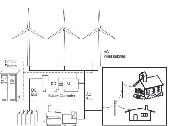
As already said in chapter1, the use of renewable energy sources presents a tremendous po-tential for many applications and especially off-grid stand-alone systems. In this context, one of the most promising applications of renewable energy technology is the installation of hybrid energy systems (HES) in remote areas, where the grid extension is costly and the cost of fuel in-creases drastically with the remoteness of the location. Recent research have shown that HES have an excellent potential, as a form of supplementary contribution to conventional power generation systemsBelfkira et al.(2008). In figure 2.1, one of the most common hybrid renewable system implemented and studied until the present date is described.
2.2
Applications
There are numerous possible applications for hybrid power systems. The most common ex-amples are:
→ Central grid connected hybrid systems (CGHS) → Isolated grid hybrid systems (IGHS)
→ Isolated or special purpose hybrid systems (ISHS) 5
6 Hybrid Energy Systems - Principles
.
AC Bus Control System DC Rotary Converter DC Bus AC AC Wind turbinesFigure C.4: Schematic of a power storage hybrid system with a rotary converter
-250 -200 -150 -100 -50 0 50 100 150 200 250 300 1 14 27 40 53 66 79 92 105 118 131 144 157 170 183 196 Time, minutes Po w er, kW Load Wind
Battery power (Charging is negative)
0 5 0 1 0 0 1 5 0 2 0 0 2 5 0 1 13 25 37 49 61 73 85 97 109 121 133 145 157 169 181 193 T i m e , m in u t e s Diesel p ow er , kW
Figure C.5: Depiction of 24-hours of operation of power storage hybrid power system
42
Figure 2.1: Schematic of a typical wind diesel hybrid system with storageCorbus(2006)
The classic example of the hybrid energy system is the remote, diesel-powered AC network (IGHS). The basic goal is to decrease the amount of fuel consumed by diesel generators and to decrease the number of hours that they operateManwell(2004).
Isolated grid hybrid systems differ in many ways from most of those connected to a central grid. First, they must be able to provide for all the energy that is required at any time on the grid or find a graceful way to shed load when they cannot. They must be able to set the grid frequency and control the voltage. The latter requirement implies that they must be able to provide reactive power as needed. Under certain conditions, renewable generators may produce energy in excess of what is needed. This energy must be dissipated in some way so as not to introduce instabilities into the systemPeças Lopes(2006).
There are basically two types of isolated grid hybrid systems which include a renewable en-ergy generator among their components. These are known as low penetration or high penetration, depending on the ratio of renewable production by the total electrical load being served. Low pene-tration, which is on the order of 20% or less, signifies that the impact of the renewable generator on the grid is minor, and little or no special equipment or control is required. High penetration, which is typically over 50% and may exceed 100%, signifies that the impact of the renewable generator on the grid is significant and special equipment or control is almost certainly required Manwell
(2004). High-penetration systems may incorporate supervisory control, so-called dump loads, short-term storage, and load management systemsNema et al.(2009). Two important considera-tions in an isolated system are whether the system can at times run totally on the renewable source (without any diesel generator on) and whether the renewable source can run in parallel with (i.e.,
2.3 Technology used 7
at the same time as) the diesel generator.
2.3
Technology used
A wide range of technology may be used in a hybrid energy system. Some say that part of the system´s steadiness is lost due to the large number of components. However, manufactures have been studying several ways to increase this reliability Morea et al.(2007). Another issue will relate to the reliability of operation and sizing of the HES, which will be discussed later in this work. Devices to be discussed include energy consuming devices (loads), renewable energy converters, fossil fuel generators, energy storage devices, power converters, control systems, and load management devices. Some of the various possible devices and arrangements that may be found in HES are illustrated in figure 2.2. The primary focus here is on isolated network hybrid systems, but much of the technology applies to other types of HES as well.
Clutch
DC machine AC Machine
Diesel engine Shaft bus
AC generators Wind turbine PV array with MPPT Diesel generators A C B U S AC loads Primary Deferrable Optional Dump Rectifier Bidirectional converter Unidirectional converter DC generators Wind turbine PV array Diesel generators AC loads Primary Deferrable Optional Dump D C B U S DC storage
Figure 2.2: Possible devices and arrangements in HESManwell(2004)
2.3.1 Renewable Energy Generators
Renewable energy generators are devices that convert energy from its original form in the renewable energy source into electricity. Renewable energy generators that are most likely to be found in hybrid energy systems include wind turbines and photovoltaic panels Gupta et al.
8 Hybrid Energy Systems - Principles
fueled generatorsGupta et al.(2008b), or fuel cellsZahedi(2007). These references are only one of the multiple cases that could be taken as an example for each type of application. At this point, it would be unreasonable to expose all the references searched. Consequently, there have been chosen the most complete and incisive articles with the highest factor rateskn:(2009).
2.3.2 Fossil Fuel Generators
Fossil fuel generators are commonly used in hybrid energy systems. Actually, most isolated power systems are based on fossil fuel, using internal combustion engines as prime movers. It is common to see diesel engine/generators in medium-sized and larger isolated systems. The smallest systems sometimes use gasoline and some very large isolated power systems occasionally use conventional oil-fired steam power plants. Diesel generators typically consist of three main functional units: a diesel engine, a synchronous generator with voltage regulator, and a governor (device which automatically regulates speed). The diesel engine is normally connected directly to a synchronous generator. A voltage regulator ensures the proper voltage is produced. The frequency of the AC power is directly proportional to the engine speed, which in turn is controlled by the governorZoulias e Lymberopoulos(2008).
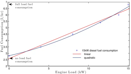
Diesel engine generators are often called on to follow the load. That means that their output must be equal to the system load less the production of any other generators that might be produc-ing energy - net load. As the load may go up and down, so must the electricity generated. This is known as part load operation. Generally, the conversion efficiency is less at part load than at full load. Fuel consumption over the full range of operation is summarized in fuel curves. In these curves, fuel consumption is graphed against engine loads (see figure2.3). Regardless of efficiency considerations, manufacturers normally recommend that diesel generators not be run below some specified minimum power level, known as the minimum load. Typically, the minimum recom-mended load is between 25% and 50% of rated. Engines run for long periods at levels below the minimum recommended can experience a number of problemsZoulias e Lymberopoulos(2008).
2.3.3 Energy Storage
Energy storage is often used in hybrid energy systems. It can be useful for ruling a mismatch between the electrical load and the renewable energy resource, and nevertheless to facilitate the control and operation of the overall system by being capable of smoothing out load fluctuations and making up for seasonal variations in renewable sources. Energy storage technologies are classified according to the energy, time, and transient response required for their operationFarret
(2006b). In terms of energy requirements, energy storage capacity can be classified regarding the density needs, for medium and long-term needs, or relatively to power density, for short and very short-term needs. In an hybrid energy system, energy storage can provide the required constant and stable output of the system, despite load fluctuations and maintenance services. It is able to provide energy for ride through lacks of primary energy resources such as wind, solar and hydropower. Energy storage as the capability of supplementing a diesel generator or a fuel cell, providing load
2.3 Technology used 9 0 5 10 15 2 2.5 3 3.5 4 4.5 5 5.5 6 6.5 7 Engi ne Load (kW) F u el C on su m p ti on (l /h r)
15kW diesel fuel consumption linear
quadratic no load fuel
consumpti on full load fuel consumption
Figure 2.3: A typical diesel engine fuel curveFarret(2006a)
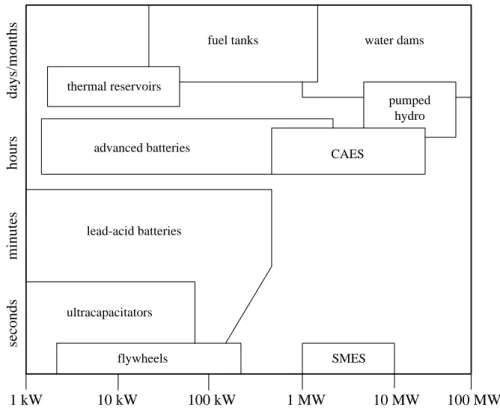
following services and increasing the generator efficiency, reducing fuel consumptions as well. A storage unit can operate in parallel with a generating unit to meet temporary higher peaks of demand than the rated generator capacity. In figure 2.4, it is possible to see both mature and emerging storage technologies organized in categories of ride-through, power quality and energy management.
Energy storage can be classified in two main applications, which is convertible use and end-use. The first one is that which can be converted back to electricity. End-use storage can be applied to a particular end-use requirement but may be, or not, converted back to electricity. There are many convertible storage media, although only a few of them are used frequently in the system configuration. Batteries are the most commonly used form in hybrid energy systems. Nevertheless, many studies have been performed for different (or emergent) forms of convertible storage. These are the less usually used, but often discussed forms, like pumped hydroelectricAnagnostopoulos e Papantonis(2007);Katsaprakakis et al.(2008), flywheelsBolund et al.(2007);Leclercq et al.
(2003), compressed airDenholm e Sioshansi(2009);Lund e Salgi(2009) and hydrogenShakya et al.(2005);Zhou e Francois(2009).
In a pumped hydroelectric system, the water is pumped from one reservoir at a low elevation up to one at a higher elevation. The amount of energy that can be stored is a function of the size of the reservoir and the difference in elevation. The overall efficiency of the storage is a function of the efficiency of the pumps and turbines (which may be the same devices) and the hydraulic losses in the pipes connecting the two reservoirs. The use of pumped storage is limited by the lack of sites where such facilities can be installed at a reasonable priceManwell (2004). The typical overall efficiency of pumped hydro systems is bounded in 65% and 77%, while the maximum depth of discharge is up to 95% without affecting their considerable (up to 50 years) service periodKaldellis et al.(2009).
10 Hybrid Energy Systems - Principles 1 kW 10 kW 100 kW 1 MW 10 MW 100 MW se co n d s m in u te s h o u rs d ay s/ m o n th s
fuel tanks water dams
thermal reservoirs advanced batteries pumped hydro CAES SMES lead-acid batteries ultracapacitators flywheels
Figure 2.4: Energy storage devices and corresponding time capacityFarret(2006b) Flywheels are kinetic energy storage devices, and store energy in a rotating mass (rotor), with the amount of stored energy (capacity) dependent on the mass and form (inertia), and rotational speed of the rotor. An accelerating torque causes a flywheel to speed up and store energy, while a decelerating torque causes a flywheel to slow down and regenerate energyRuddell(2003). Fly-wheels typically store relatively small amounts of energy, but they can absorb or release the energy at high rates. Thus in hybrid power systems they can be used to smooth short term fluctuations in power (on the order of seconds or minutes) and they can facilitate system controlKaldellis et al.
(2009).
Compressed Air Energy Storage (CAES) systems store energy by compressing air within an air reservoir, using a compressor powered by off-peak/low cost electric energy. Three reservoir types are generally considered: naturally occurring aquifers (such as those used for natural gas storage), solution-mined salt caverns, or mechanically formed reservoirs in rock formations. Dur-ing discharge, the plant’s generator operates to produce power usDur-ing a conventional natural gas combustor and the stored air. During charging the turbine operates in reverse (as a motor) to provide mechanical energy to the air compressors. A special clutch is required to allow the tur-bine/generator to operate in two directions Schoenung e Burns (1996). CAES is an available technology for large-scale (1MW-100MW) energy storageKaldellis et al.(2009).
Similar to electricity, hydrogen is a high-quality energy carrier, which can be used with a high efficiency and zero or near-zero emissions at the point of use. Hydrogen can be used for power generation, and could replace current fuels in all their present uses. Hydrogen can be produced using a variety of starting materials, derived from both renewable and nonrenewable
2.3 Technology used 11
sources, through many different process routes. In an hybrid system, the electrolysis of water is widely used. The process of producing hydrogen from renewable sources is, more precisely, the hydrogen production by the electrolysis of water, where the main power input is electrical power produced from the conversion of the renewable sourcesGupta(2008).
End-use storage, as opposed to convertible storage, refers to the situation in which some prod-uct is created through the use of electricity when it is available. The prodprod-uct is then stored and made available when it is needed. Load management schemes often incorporate some end-use storage.
Thermal energy storage (TES) is the concept of generating and storing energy in the form of heat or cold for use during peak periods. Thermal energy storage has been used for centuries, but only recently have large electrical users taken advantage of the technique for cost management. The process involves storing Btu´s (or lack of Btu´s) for use when either a heat source or a heat sink is required. The use of eaves, root cellars, ground coupled heat pump systems, and adobe type thermal mass could all be considered forms of thermal storageTurner(2006). Pumped water and pure water technologies are other types of end-use storage. The first one is quite similar to the pumped hydroelectric with the difference that, when the storage is elevated, the water flows by gravity to the point of use, so no further inputs of externally produced energy are required. The second one is a less common form of energy storage, bases on the production and then storage of pure water from salty or brackish water. This process can involve ultrafiltration, reverse osmosis, or vapor compression evaporation to produce pure waterHadjipaschalis et al.(2009).
2.3.4 Power Converters
For any hybrid energy system to function properly, it is common that one or more power converter to be incorporated into the system. These are either electromechanical or electronic devices.
Within electromechanical power converters, there are at least two types that have been used in hybrid energy systems - rotary converter and the synchronous condenser. A rotary converter is an electromechanical device that converts AC to DC or vice versa. When it is converting AC to DC it is a rectifier. When operating the other way it is an inverter. The rotary converter consists of two rotating electrical machines that are directly connected together. One of them is a DC machine; the other is an AC machine. Either of them can run as a motor or generator depending on the intended direction of power flow. The AC machine can be either an induction machine or a synchronous machine. The one which will be used depend on the requirements of the system.
Rotary converters have the advantage that they are a rugged and well-understood technology that has been around for many years. Their disadvantage is that their costs are higher and their ef-ficiencies are lower than are electronic devices that can serve the same purposeGreenberg(1999). A synchronous condenser, or compensator, is a synchronous motor that is not attached to any driven equipment.Its field is controlled by a voltage regulator to either generate or absorb reactive power as needed to support a system’s voltage or to maintain the system power factor at a specified level. Synchronous condensers are used in hybrid energy systems when there are, for at least some
12 Hybrid Energy Systems - Principles
of the time, no other synchronous machines connected. This is often the case in those systems that include diesel generators but that are intended to allow all the diesels generators to be turned off under some circumstancesWeedy(1972).
Many of the electronic converters serve similar functions to the electromechanical devices described previously, but have a number of advantages, such as lower cost, higher efficiencies, and greater controllability. The devices of greatest interest include rectifiers, inverters, dump loads, and maximum power point trackersManwell(2004).
A rectifier is a device that converts AC to DC, commonly used to charge batteries from an AC source. Single-phase diode rectifiers require a rather high transformer VA rating for a given DC output power. Therefore, these rectifiers are suitable only for low to medium power appli-cations. For power output higher than 15kW, three-phase or polyphase diode rectifiers should be employedRashid(2001).
An inverter is a device that converts DC to AC, used to supply individual AC loads from a DC source or a battery bank.. The primary switching elements are either silicon controlled rec-tifiers (SCRs) or power transistors (IGBTs). They are arranged in a bridge circuit and switched on (and off, in the case of transistors) in such a way that an oscillating waveform results. Some inverters operate in conjunction with other devices that set the system frequency. These are re-ferred to as line commutated. Other inverters have the capability to set frequency themselves (self-commutated)Rashid(2001).
One component that may be required in hybrid power systems but is uncommon in conven-tional isolated systems, is a dump load. A dump load is used to protect against an excess of power in the network. Such an excess could arise during times of high renewable contribution and low load. Excess energy could lead to grid instability. The dump load may be a real device, based on power electronics or switchable resistors. In some cases, dissipation of excess power may be accomplished without the use of a dump load. An example is the dissipation of excess wind power by furling the rotor or blade pitch controlFarret(2006a).
In systems using PV cells, the array voltage is given by the match voltage of the connected load. It is sometimes useful to use power conditioning equipment to match the load with the characteristics of the PV cell. One method of carrying this in practice is to use a maximum power point tracker (MPPT) to maximize the PV system output. MPPT are devices that keep the impedance of the circuit of the cell at levels corresponding to best operation, and also convert the resulting power from the PV array so that its voltage is the one required by the loadDuffie(1991)
2.3.5 Supervisory Controller
Many hybrid systems, especially the more complex ones, have a supervisory controller to en-sure proper operation of all the devices within the system. The possible functions of a supervisory controller are illustrated in figure 2.5.
2.4 Energy Loads 13
SUPERVISORY CONTROL
Diesel generators Coupled diesel clutch
Optional Load Rectifier/Inverter
Charge controller Battery switch
Dump Load
Deferrable load
Figure 2.5: Supervisory control functionsManwell(2004)
2.4
Energy Loads
The energy supplied by a hybrid system can be categorized in a variety of ways. The first has to do whether the energy supplied is electricity or heat (thermal load). Within the electrical category, electricity loads are often divided into primary and secondary loads.
Primary loads are those that must be served immediately, at a specific time. Demand associated with lights, TV, household appliances are examples of primary energy loadsFarret(2006a).
Secondary loads are associated with load management, and they may be further divided in what are known as deferrable and optional loads. Deferrable loads have some flexibility in when they are served (within a defined time interval). The inherent storage ability of battery-charging stations and water pumps, as well as the flexibility as to when the system can serve them, classifies them as deferrable loads. Optional loads, as the name refers, are only served if there happens to be sufficient excess energy available to do soFarret(2006a).
Regardless of the load type, it may be noted that loads frequently vary significantly from one season to the next as well as over the week and over the day.
2.5
Renewable Energy Resources
2.5.1 Wind
Ultimately wind resources are driven almost entirely by the sun’s energy, causing differential surface heating, but they tend to be very dependent on location. Over most of the earth, the average wind speed varies from one season to another. It is also likely to be affected by general weather patterns and the time of day. It is not uncommon for a site to experience a number of days of relatively high winds and for those days to be followed by others of lower winds,
14 Hybrid Energy Systems - Principles
strongly interfering with the operation planing of an hybrid system comprehending wind turbines The wind also exhibits short term (seconds to minutes) variations in speed and direction, known as turbulenceBurton(2001).
2.5.2 Solar Radiation
The solar radiation resource is fundamentally determined by the location on the earth´s surface, the date, and the time of day. Those factors will determine the maximum level of radiation. Other factors, such as height above sea level, water vapor or pollutants in the atmosphere, and cloud cover, decrease the radiation level below the maximum possible. Solar radiation does not experience the same type of turbulence that wind does, but there can be variations over the short term. Most often, these are related to the passage of cloudsRosa(2005).
2.5.3 Hydropower
The hydropower resource at a site is a function of the amount of flowing water available in a river or stream and the change in elevation. The head is usually relative constant (affected only by high water during storms), but the amount of water available can vary significantly over time. The average discharge is determined by rainfall and the drainage area upstream of the site on which the rain falls. Discharge will increase after storms and decrease during droughts. Soil conditions and nature of the terrain can also affect the discharge. Short term fluctuations are normally insignificantRosa(2005).
2.6
Economics
The choice on whether or not a HES is in fact used, and what components constitute him, is forcefully related to the economics of the system. The cost of a hybrid system is primarily deter-mined by two factors: the cost of the system and the amount of useful energy that is produced, i.e. not the energy production but the energy truly used for consumption. Other factors are concerned when talking about the economics of an HES, like the cost of conventional energy, lifetime of the system, maintenance costs, and financial costsManwell(2004).
The cost of the system is primarily affected by the individual´s components cost that make up the system, and generally the renewable energy generators themselves. Diesel generators are also costly, but considerably less so than wind turbinesManwell(2004).
Economics of hybrid energy systems are typically evaluated by a technique known as life cycle costing.This method takes account of the fact that HES have relatively high initial costs but long lifetimes and low operating costs. These factors,together with various financial parameters, are used to predict present value costs, which can then be compared with costs from the conventional alternativesFarret(2006a).
Chapter 3
Hybrid Energy Systems - Design
Considerations
3.1
Introduction
After a pre-feasibility study about the climacteric conditions and load profiles, the proper siz-ing of system components is made based on specific location weather data and maximum capacity. Being the unit sizing one of the most important factors when designing the HES, it is common sense that it will play an important part deciding the economic and reliability of the system.
The literature on this subject is very wide but limited. From the references studied, it is a fact that photovoltaic-wind hybrid systems are the most frequently analyzed. Very complete and with a remarkable explanatory factor articles were present by authors like Ajai GuptaGupta et al.
(2008b),Gupta et al.(2008c),Gupta et al.(2008d), simply making references to more complex studies on other renewable sources hybrid mixed such as hydro, biomass and others.
From this point on, an elucidative analysis of various unit sizing methods will be reviewed, specifically about the means by which the renewable energy generators capacity is determined as well as the capacity of the diesel generator and the number of batteries to guarantee load´s imposed autonomy.
3.2
Brief Review on Design Techniques
In 1983, Borowy and SalamehOfry e Braunstein(1983) proposed the loss of power supply probability as a technique for designing stand-alone solar electrical photovoltaic systems. Hongx-ing Yang and Lin LuYang et al.(2007) have presented a hybrid solar-wind system Optimization Sizing (HSWSO) model, to optimize the capacity sizes of different components of hybrid solar-wind power generation systems employing a battery bank. The application was based on the loss of power supply probability (LPSP) concept and the levelised cost of energy (LCE) concept, being
16 Hybrid Energy Systems - Design Considerations
the LPSP considered the criteria for sizing the system. This technique represents the probability that an insufficient power supply results when the hybrid system is unable to satisfy the load de-mand. Others have used the LPSP approach to design hybrid systemsBorowy e Salameh(1996).
Some differences can be seen from a probability method with LPSP, which is shown at para-graph above, and an analytical method with LPSPAbouzahr e Ramakumar(1991)
Francesco Bonanno et al.Bonanno et al.(1998) developed a logistical model for performance evaluation of hybrid generation systems (HGS). The special feature consisted in an auxiliary fic-titious source introduced to the hybrid system in order to obtain the power electric balance at the busbars during the simulation stage in any case of ill-sized components. The auxiliary source represented a compensatory source of any power imbalance of the power plant during the power load request, and it allowed performing the simulation runs without interruptions. The observed imbalance powers were then used to update, in each iteration, the optimal system design.
Another sizing method is explained in Chedid et al.(2005). Here, a multi-objective design methodology was proposed based on the ε-constraint method to minimize the cost of the HES, taking in account gas emission minimization as a constraint of the problem. In a first stage, linear programming was used to minimize the total system cost while satisfying the energy demand, reliability, stability and battery constraints. The result of this first stage pointed to an optimum design of the system. Secondly, a same approach was used with the purpose to minimize C02 emissions as the main function of the multi-objective problem. The multiple results of the n-1 constraint equations form a multi-objective problem which is solved by the ε-constraint.
A simple but effective approach was developed by Pradeep K. Katti and Mohan K. Khed-kar Katti e Khedkar (2007). The authors fixed first an energy flow strategie for the HES. The second step was selecting commercially available unit sizes for wind turbines, PV panel, as per site matching strategy and battery storage. Since the rating for the wind turbine far exceeded the ones of a single PV panel, they keep the number of turbines constant and increased the number of PV panel until the system was balanced. Next step consisted in experimenting different number of wind turbines as needed. For last, the LPSP was calculated for each combination that satisfied that the curve of ∆P vs. time had an average zero value over a given period of time.
B. Ai et al.Ai et al.(2003) developed a different approach to unit sizing PV-wind hybrid sys-tems components. By fixing the capacity of wind generators, the whole year’s LPSP values of the hybrid systems with different capacity of PV array and battery bank were calculated. Given the LPSP value, the trade-off curve between the PV array and battery bank capacity of the system meeting this load demand was drawn, then the optimum system configuration could be uniquely identified by drawing a tangent to the trade-off curve with the slope representing the relationship between PV module and battery costs. The authors include sensitivity factors in this mathematical models, like the surplus energy (Esurp), the loss of power supply (LSP), power failure time (Tf), loss of load probability (LLP) and the already used by others Yang et al.(2007) loss of power supply probability. By ensuring one initial configuration for the system, those parameters where constantly changing so the best design could be meet. This looks like a time consuming work but the results were very satisfying. In Beyer e Langer (1996), a trade-off method was used as
3.2 Brief Review on Design Techniques 17
well. The author used this approach because of the conflicting objectives and the uncertainties evolving the problem. The objective aimed not to pretend to find a unique optimal solution, rather an organized way of evaluating the relationship between the attributes and the uncertainties, elim-inating many plans that were inferior and, what as left, were plans which represented a reasonable compromise. The attributes to minimize were the capital investment and the loss of load probabil-ity and the uncertainties under which the design should be carried were associated with the load demand and the renewable energy sources availability. The solutions were chosen by the decision theory of the trade-off method, in which the solution is dominated if exists another one that is better in one attribute and not worse is another.
One of the most complex systems in the literature reviewed, was given by Gupta, A. inGupta et al.(2007a). The complexicity of the hybrid system was due to the large number of energy re-sources that composed the hybrid system: Small Hydro Power (SHP), Solar Photovoltaic (SPV), Wind Energy System (WES), Biomass Energy System (BES) and a Diesel Generator (DG). This study was made for particular interest of a cluster of villages in Jaunpur block district Tehri Garhwal of Uttaranchal state, India, which can not have acess to electricity because of the consid-eration by Uttaranchal Renewable Energy Development Agency (UREDA) to be remote and not economically viable for electrification by grid extension. By studying the assessment of energy potential and energy demand, the authors then applied a general model formulated in the basis of linear programming. Like in many other literature, the main objective was to reduce the total cost of providing energy to all the end users. We may look at this problem like the minimization of the amount of fuel consumed by the diesel generator, as this is the most expensive source for system dispatch.
In Gupta et al.(2008a) an action plan for the design of an hybrid renewable energy system was given. A step by step guide was presented so that a conscience and logical decision could be made. An explanation for the power supply of a certain village is given by figure3.1.
The arguments used were quite simple, but very effective. First, certain criteria should be followed while selecting the villages for hybridization, i.e, the villages should be remote but rea-sonably accessible. Energy demand was another step to be studied to distinguish different types of needs assessment like household load, community demand, commercial demand and industrial demand. In order to estimate which villages would be suitable for which type of renewable energy source, a resource assessment was made based on the primary information collected from the field and on the secondary data available from different sources. The suggested thresholds for different resources for determining feasibility are given in the table3.1. For last, a unit cost of resources was obtained by adding the capital recovery cost and operation & maintenance cost per unit of energy.
R.Ramakumar et al. presented inRamakumar et al.(1992,1995) a knowledge-based approach to the design of integrated renewable energy systems. With a year data, the authors divided into as many number of time-sections (seasons) as needed such that the resources and the loads had reasonably similar daily variations or were constant during each period of time. The knowledge-based technique was then used for each time-section to find the ratings of converters and the energy
18 Hybrid Energy Systems - Design Considerations
OPTIONS DRAWBACKS SOLUTIONS
Grid power with T&D Connection
· High cost of delivered power
· High line loss
Grid power with T&D Connection
· High operation costs
· Fuel transportation
· Short operation lifetime
· Interruptible supply
Renewable Energy
· High investment costs
· Specialized maintenance
· Intermittent energy resources
HYBRYD
SYSTEM
Figure 3.1: Power supply options for village electrificationGupta et al.(2008a)
needs at the desire rehability level, subject to resource availability and at minimum capital cost. The final system design was base on the seasonal designs and the prioritization of the various seasons. If they were selected on the worst possible combination of resource availabilities and loads, an amount of energy excess would be available and the overall design failed to be cost effective.
Simulation approachBeyer e Langer(1996);Celik(2002) is another methodology used to de-sign hybrid energy systems. The core of the procedure is formed by a time-step simulation for the evaluation of the system performance, using as input data, an hourly time series of meteorological data. To begin the simulation process, the user must first fix a level of desire reliability for the load supply (LLP) so that the performance of an initial system configuration could be simulated for a period of one or several years. The size of the components was then varied in an iteration until the desired performance was reached. Using a matrix search with a reasonable range of component sizes, a certain number of feasible configurations could be identified and, to decide one of those
Table 3.1: Amount of a site resource typically needed for feasibilityGupta et al.(2008a) Site Resources Typically needed
Full sunlight(hrs/day) ≥ 2 Wind speed(m/s) ≥ 4 Stream speed(m/s) ≥ 1
Biomass(24kg − 1kWh) Depend upon cattle number Fuel cost(e/l) Depends upon application
3.2 Brief Review on Design Techniques 19 Renewable Energy Option Delphi Study Users’ Restricting Factors Cost Efficiency Social Acceptance Technology Availability Maintenance Intermittent Energy Supply Failure Rate Analysis Social Acceptance for Each System ‘S’ Demand Constraint Potencial Constraint Reliability Index of the Systems Critical Factors for Optimization Optimal Renewable Energy Option ‘X’ O P T I M I Z A T I O N Renewable Energy Demand End-use Wise Lighting Cooking Pumping Heating Cooling TransP. Solar, Wind, Biomass Fuelwood, Biogas, Ethanol Renewable Energy Demand for 2020-21 Potencial of Renewable Energy Sources Two-Stage Least Square Technique Commercial Non-commercial
Figure 3.2: Flow-chart of a linear programming method including a Delphi studyIniyan e Sumathy
(2003)
possible configurations, an optimization was applied according to a give figure of merit composed by the the number of components and the cost that the configuration implied. It is important to note that this approach was considered, by the authors, restricted to low LLP case systems. For in-termediate LLP, the system was governed by seasonal meteorological conditions and so, the worst month approach should be abandoned.
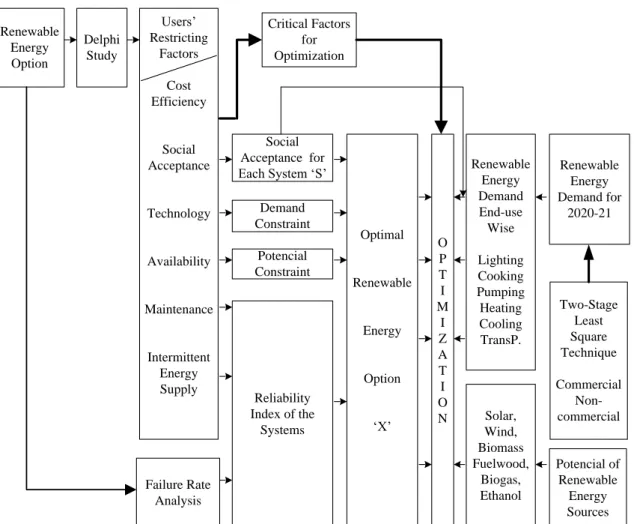
Many authors studied the application of different models to developing countries with a huge potential in renewable energy resources. In Iniyan e Sumathy(2000,2003), linear programming was applied to renewable energy models for different various-ends in India. Like almost all the literature reviewed, the main objective as to reduce the initial capital cost and the reliability of the system. Moreover, a Delphi study (see figure 3.2) was conducted to determine the social acceptance and the percentage use of renewable energy sources in different end-uses (lighting, cooking, pumping,...). When the social acceptance factor arrived from the Delphi study, it was used as a constraint in the model.
Kabouris et al. Kabouris e Contaxis (1992) used dynamic programming optimization tech-niques for determining the optimal expansion plan of an autonomous generation system including
20 Hybrid Energy Systems - Design Considerations
diesel units, wind generators and photovoltaic generators. The total operation cost in a determinate year was considered under some planning and operational constraints like the maximum number of additions of each type of system component to be installed in that year, by an upper limit, so that this constraint represents limitations on capital investment. Diesel units reserve margin was also considered as a constraint. By limiting the interval operation of the diesel generator in percentage of peak load, it was possible to guarantee the system reliability. This procedure was done to limit a maximum wind and solar power penetration as well. The methodology processed the cost of the candidate additions period inflation during the expansion period, the estimate cost of fuels and the expected economic rates. In the end, a forward-backward dynamic programming algorithm was used to determine the optimal expansion policy and, if requested, it could also determine suboptimal solutions
A review of more than 90 published papers was made by S. D. Pohekar and M. Ramachan-dran Pohekar e Ramachandran (2004) where the applicability of various methods and models, concerning multi-criteria decision were analyzed.
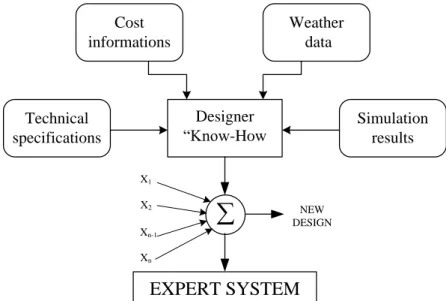
An expert system was presented by Morea, F. et al.Morea et al.(2007). The algorithm was made on the basis of dynamic simulation, using a conventional simulation model, and all rele-vant information on cost, maintenance schemes and, for typically Italy and other countries in the Mediterranean area load profiles. The technology used included photovoltaic, wind generators, battery storage and a backup diesel. The expert system required generally information available at the initial stage of the project to determine the best hybrid mix unit sizing. Based on a neural network, the users wish to overcome the drawbacks of existing simulation software. The software initially used was HOMER and then, the neural network was trained using the generated database. The objective was to use a wide knowledge (technological specifications, costs, human experience in design) for redesigning the system after the simulation was done by HOMER. Figure3.3shows the basics of the expert system.
Designer “Know-How
EXPERT SYSTEM
X1 X2 Xn-1 Xn NEW DESIGN Cost informations Weather data Simulation results Technical specifications3.2 Brief Review on Design Techniques 21
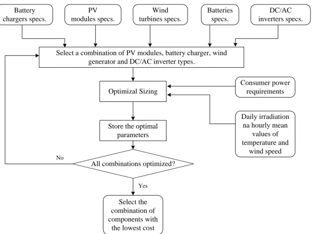
Koutroulis E. et al Koutroulis et al. (2006) proposed a methodology to calculate, among a list of commercially available system devices, the optimal number and type of units to ensure a 20 year operation with a minimized system cost, subject to the constraint that the load energy require-ments were completely covered, resulting in zero load rejection. The main objective (total cost), was the minimization function, implemented using genetic algorithms. This technique was used due to the fact that the ability to attain the global optimum was relative computation simplistic, when compared to conventional optimization methods such as dynamic programming and gradi-ent techniques. From a set of individuals which were composed by the system compongradi-ents, the algorithm chose the best combination in the evolution process so that after the maximum iterations defined by the user, the best set of components with the low cost were chosen. The methodology can be seen in figure 3.4.
Battery chargers specs. PV modules specs. Wind turbines specs. Batteries specs. DC/AC inverters specs.
Select a combination of PV modules, battery charger, wind generator and DC/AC inverter types.
Optimizal Sizing
Store the optimal parameters Consumer power requirements Daily irradiation na hourly mean values of temperature and wind speed All combinations optimized?
Select the combination of components with
the lowest cost
Yes No
Figure 3.4: Flowchart of the genetic optimization methodologyKoutroulis et al.(2006) Yang Yang et al. (2009) also developed an optimization technique with genetic algorithms but a little more complexed. The author, instead of attaining to reach zero load rejection, he used the LPSP and the annualized cost of system concepts. The decision variables included in the optimization process were, as usual, the PV module number, wind turbine number, battery number and, for a more complex and complete algorithm processment, the PV slope angle as well as the wind turbine installation height. Like in Koutroulis et al.(2006), the author here justifies the genetic algorithm application like being generally robust in finding global optimal solutions,
22 Hybrid Energy Systems - Design Considerations
particularly in multi-nodal and multi-objective optimization problems.
Still in the area of artificial intelligence applications in electric power systems, S.M. Hakimi and S.M. Moghaddas-TafreshiHakimi e Moghaddas-Tafreshi(2009) presented a novel intelligent method for optimal sizing of a stand-alone hybrid power system in Kahnouj area, south-east Iran. The system consisted of fuel cells, wind units, electrolyzers, an anaerobic reactor and some hy-drogen tanks. The system used biomass as an available energy resource. The optimization process was carried out by a particle swarm algorithm who chosed the best components, by simulating a flock of birds flying together to the optimal point. If the constraints of the problem were satisfied, the solution was a best optimal individual of the problem, and was carried to the next iterations like the best global solution, until the maximum iterations were achieved.
Some authorsFung et al.(1993) used simulated annealing techniques applied to hybrid energy systems. This approach consists in a random search method similar to the iterative improvement algorithm, but it may accept inferior solutions based on a probabilistic measure. The algorithm was therefore possible to escape from being trapped within local minimum points and to seek after the global or near global solution in the overall solution space. Therefore, starting from an initial system design, the total cost was calculated and in the next iteration, the new unit sizing compo-nents were perturbed, while satisfying all the constraints. The new solution was only accepted if the new cost was lower.
Indel Real et al. (2009) the energy hub formulation was exploited, defined as an interface among energy producers, consumers and transportation infrastructure. The objective function was based on cost and efficiencies of the system elements, while taking into account the hub model, energy prices, input power flows availability and output energy demands. The optimization was stated as a multi-period nonlinear constrained problem. The system incorporated wind generators, batteries and an intermediate hydrogen storage to be optimized. Results of the hybrid system study reveal improvements in investment costs of almost 30% when compared with the equivalent hydrogen-only and battery-only storage systems.
Y.P. Cai et alCai et al. (2009) implemented an interval parameter based two stage program-ming model for supporting community scale renewable energy management. The methodology was based on interval linear programming, two-stage programming and superiority-inferiority-based fuzzy-stochastic programming. This allowed the simulation process of unit sizing to incor-porate complexities and multiple uncertainties, both probabilistic and possibilistic. The aim was to developed such method that could be applied to a case of long-term renewable energy planning for three communities. The final results prove the pre-objectives of the work, by generating deci-sion alternatives and thus helping decideci-sion makers to identify their desired policies under various economic-reliability system constraints.
In Gupta et al. (2009), a mixed integer linear mathematical programming model has been developed to determine the optimal configuration, including the assessment of the economic pene-tration levels of photovoltaic array area. The novel methodology consisted in the incorporation of a constant cost (cost/unit) for each of the proposed resource (small hydro, biomass, PV modules, wind turbine, diesel generator) in the cost objective function so that the ones with lesser unit costs