Artigo
*e-mail: [email protected]
HYDROLYTIC DEGRADATION BEHAVIOR OF PLLA NANOCOMPOSITES REINFORCED WITH MODIFIED CELLULOSE NANOCRYSTALS
Everton Luiz de Paulaa,*, Valdir Manob, Eliana Aparecida Rezende Duekc and Fabiano Vargas Pereirad
aDiretoria de Educação Aberta e a Distância, Universidade Federal dos Vales do Jequitinhonha e Mucuri, 39100-000 Diamantina – MG, Brasil
bDepartamento de Ciências Naturais, Universidade Federal de São João Del-Rei, 36301-160 São João Del Rei – MG, Brasil cLaboratório de Biomateriais, Pontifícia Universidade Católica de São Paulo, 18030-070 Sorocaba – SP, Brasil
dDepartamento de Química, Universidade Federal de Minas Gerais, 31270-901 Belo Horizonte – MG, Brasil
Recebido em 16/01/2015; aceito em 13/05/2015; publicado na web em 26/06/2015
Bionanocomposites derived from poly(L-Lactide) (PLLA) were reinforced with chemically modified cellulose nanocrystals (m-CNCs). The effects of these modified cellulose nanoparticles on the mechanical and hydrolytic degradation behavior of polylactide were studied. The m-CNCs were prepared by a method in which hydrolysis of cellulose chains is performed simultaneously with the esterification of hydroxyl groups to produce modified nanocrystals with ester groups. FTIR, elemental analysis, TEM, XRD and contact angle measurements were used to confirm and characterize the chemical modifications of the m-CNCs. These bionanocomposites gave considerably better mechanical properties than neat PLLA based on an approximately 100% increase in tensile strength. Due to the hydrophobic properties of the esterified nanocrystals incorporated into a polymer matrix, it was also demonstrated that a small amount of m-CNCs could lead to a remarkable decrease in the hydrolytic degradation rate of the biopolymer. In addition, the m-CNCs considerably delay the degradation of the nanocomposite by providing a physical barrier that prevents the permeation of water, which thus hinders the overall absorption of water into the matrix. The results obtained in this study show the nanocrystals can be used to reinforce polylactides and fine-tune their degradation rates in moist or physiological environments.
Keywords: bionanocomposite; chemically modified cellulose nanocrystals; poly(L-Lactide); polymer degradation.
INTRODUCTION
Poly(L-Lactide), or PLLA, is a bio-based polymer obtained exclusively from renewable resources (such as cornstarch). It can be degraded into carbon dioxide and water in natural environments and is today the predominant biodegradable aliphatic polyester on the market.1,2 PLLA finds numerous applications in different fields, primarily in packaging and medical applications such as surgical sutures, systems for controlled release of drugs, orthopedic devices and support in tissue engineering.3,4 This polymer is one of the most frequently used material in the biomedical field due to its good bio-compatibility, low toxicity, relatively good mechanical properties and non-immunogenicity.5-8 The polylactides belong to the class of poly(α-hydroxy acids), which have ester bonds that make them hy-drolytically unstable: they degrade upon contact with a physiological environment. The degradation products are absorbed by the body, as they are natural byproducts of carbohydrate metabolism.9
Considering practical applications of PLLA as a biodegradable polymer, it is important not only to understand but also to control its degradation process. In vivo degradation of biodegradable aliphatic polyesters usually occurs by chemical hydrolysis reactions of the ester linkages in their backbone,10 and it is affected by many factors, such as monomer structure, molecular weight, crystallinity (χ), pH, temperature, and the presence of different agents such as microorgan-isms and enzymes.10-13
Despite the potential for application of polylactides in the biomedical area, factors such as the hydrophobic character of the polylactides and their relatively poor mechanical properties for some applications have limited their use. However, it has been
demonstrated that some properties can be improved by modifying these polymeric materials through various strategies, such as the synthesis of copolymers14,15 and the preparation of blends16,17 or nanocomposites with various particles such as nanoclays,18 carbon nanotubes19 or cellulose nanocrystals.20,21 In recent years, the addition of cellulose nanocrystals (CNC) in biodegradable polymeric mate-rials has attracted significant attention mainly due to the excellent mechanical properties and the renewable character of these “green” nanoparticles.21-25 CNC consist of needle-shaped nanoparticles with high crystallinity, high surface area, an average length of 100-200 nm and a diameter in the range of 5-10 nm, depending on the source of cellulose and the preparation method.26 CNC can be obtained by a controlled acid hydrolysis from a large variety of natural sources of cellulose such as cotton, bamboo, wood or even agricultural residue.26,27 In addition to their mechanical properties and renewable nature, the advantages of using CNC rather than inorganic fillers include high aspect ratios, low cost, low density and a nonabrasive nature that facilitates easy processability.
When CNC are employed for reinforcement in polymer matrices, the resulting nanocomposites generally exhibit superior mechanical, thermal and barrier properties, even when the cellulose nanoparticles are in low concentration.23,28 Considering the polar nature of the CNCs, one of the major challenges of preparing nanocomposites is obtaining appropriate compatibilization of the nano-reinforcements with hydrophobic polymers to achieve good dispersion levels of the filler within the polymeric matrix. Methods to achieve dispersion of the cellulose nanoparticles in these materials include the use of chemical surface modification of the CNC29,30 and the polymer grafting on the nanocrystals’ surface.29,31-37
behavior of the nanocomposites. The modified-CNC were prepared by a method in which hydrolysis of the cellulose source and es-terification of hydroxyl groups were performed in a single step to produce more hydrophobic functionalized cellulose nanocrystals. The nanocomposites were prepared by casting, and the hydrolytic degradation was performed in a buffer solution, mimicking the physi-ological environment.
EXPERIMENTAL
Materials
Eucalyptus kraft wood pulp was used as cellulose source. Sulfuric acid, sodium hydroxide, hydrogen peroxide, sodium chlorite, and chloroform were purchased from Sigma-Aldrich. Acetic acid 99%, hydrochloric acid, sodium monohydrogen phosphate, and potassium dihydrogen phosphate were purchased from Synth. All reagents were used without further purification.
Preparation of unmodified CNC and chemically modified CNC
To prepare unmodified (u-CNC) and modified (m-CNC) cellulose nanocrystals, eucalyptus wood pulp was first treated with NaOH solution and bleached with an acetate buffer and aqueous chlorite (1.7 wt% in water). Suspensions of unmodified CNC were prepared by acid hydrolysis of treated cellulose pulp using sulfuric acid as de-scribed in the literature, with minor modifications.22,23 Briefly, 10.0 g of milled and bleached cellulose was added to 160.0 mL of a sulfuric acid solution (65 wt%) and mechanically stirred for 40 min. After, the dispersion was washed three times by repeated centrifuge steps. Finally, the suspension was washed using dialysis against deionized water (until pH=7.0) and ultrasonicated.
For the preparation of chemically modified CNC (m-CNC), the hydrolysis and esterification of hydroxyl groups of cellulose were performed in a single step using a similar method previously described in the literature.36 The bleached cellulose wood pulp (5,0 g) was added to a mixture of sulfuric acid (250 mL of a solution at 20 wt%) and trimethylacetic acid (10.0 mL of a solution at 0.8 wt%). Hydrolysis was performed at 55 °C for approximately 72 h. Following the re-action, the suspensions were diluted, washed using three repeated centrifuge cycles, dialyzed against deionized water, sonicated for approximately 5 min (Unique Sonicator, 40 kHz) and finally filtered using a filter paper with a 20 µm pore size. The final concentration of the CNC dispersions was approximately 1 wt%.”
Preparation of Poly(L-lactide)
Poly(L-lactide) was synthesized by bulk polymerization using (Sn(Oct)2) as catalyst. The polymerization was performed using the ring-opening polymerization (ROP) of L-lactide by adding the L-lactide monomer to the catalyst in a glass vial, with the monomer-catalyst ratio approximately 5000. The mixture was frozen in liquid N2, and then the vial was vacuum treated to remove moisture and gases dissolved in the monomer and catalyst. After this process, the ampoule was sealed and immersed in a silicone bath at 130 °C for 24 h. After this period, the polymer was dissolved in chloroform, precipitated in ethanol and dried in a vacuum oven at 60 °C for 8 h. Preparation of nanocomposites
The nanocomposites were prepared by casting, adding PLA pel-lets in chloroform (10% w/v), which was stirred using a magnetic stirrer at room temperature until the pellets were fully dissolved. After,
dispersions of m-CNC in chloroform were added on this polymer solution and the suspensions were mixed for 2 h before placed them into Teflon® dishes. The mixture was allowed to evaporate at room temperature and films were dried in a vacuum to remove residual solvent. The formulations prepared were 0, 1 and 5% by weight of m-CNC. The samples were named PLLA, PLLA-1%, and PLLA-5% for 0, 1, and 5% m-CNC content, respectively.
Hydrolytic degradation
The hydrolytic degradation of the PLLA and the nanocompos-ites was performed in 5 mL of phosphate-buffered solution (PBS; pH = 7.4). The samples were placed in test tubes containing the buffered solution and were immersed in a water bath at 37 °C. At predetermined periods (2, 4, 8, 10, 12, and 16 weeks), the samples were removed from the buffered solution, rinsed with deionized water, dried, and weighed to determine the residual mass. After the hydrolytic degradation test, the specimens were kept in a desiccator for characterization.
Instrumental analysis
Transmission electron microscopy (TEM) images of u-CNC and m-CNC were taken using a FEI Tecnai G2-Spirit with 120 kV acceleration voltage. Drops of ~ 0.01 wt% unmodified and modi-fied CNC suspension were deposited on a carbon/Formvar-coated copper (300 mesh) electron microscopy grid. The samples were subsequently stained with 2% uranyl acetate solution to enhance the microscopy resolution.
Infrared spectroscopy (FTIR) was performed using a Perkin Elmer FT-IR spectrometer (GX). The infrared spectra were obtained in the 4000 – 400 cm-1 region in film samples on the ZnSe window.
X-ray diffractometry measurements were performed on a SHIMADZU (XRD6000) X Ray diffractometer with a CuKα radia-tion source (λ = 0.154 nm) and in the 2θ-range of 10-35° in steps intervals of 0.07θ.
Elemental analysis was performed using a CHN Perkin-Elmer analyzer. CHN results were used to determine the degree of substi-tution (DS) of the m-CNC, which is measured by the number of hydroxyl groups substituted by the acid residue per unit of anhy-droglucose. The methodology used here was reported by Siqueira et al.38 The DS was calculated using the equation:
72.07 −(C ×162.07) (85.05×C)−60.05
DS= (1)
In this equation, 72.07 is the relative carbon mass of the anhydroglucose unit (C6H10O5), 162.07 is the molecular weight of this unit, 85.05 is the molecular weight of the acid residue (C5H9O) expected to link with the nanocrystal, and 60.05 is the relative carbon mass of this unit. The obtained values were the averages of two measurements.
Contact angle measurements were performed at ambient tempera-ture using a dynamic drop tensiometer (DSA10, KRUSS, Germany). CNC and m-CNC powder were compacted under a pressure of 20 MPa with a KBr press to obtain samples with homogeneous surfaces. Two different liquids, with different dispersive and polar surface ten-sions, were used to determine the surface energy of the nanocrystals, diiodomethane and formamide. The dispersive and polar components of the surface energy of the unmodified and modified CNC were measured by applying the Owens–Wendt approach:
(1 cos ) 2 d d 2 p p
L L S L S
where γ,γP and γd are, respectively, the total, polar and dispersive surface energy. The subscripts L and S refer to the surface of the liquid and solid, and θ denotes the contact angle between the liquid and the solid substrate.
Mechanical tensile testing was carried out using an Emic Universal Testing Instrument (Model DL2000) with a 1 kN load cell and crosshead speed of 2 mm min-1. Samples were prepared by cutting strips from the films of 8 cm x 2.5 cm (length x width). Tensile data were averaged over at least five samples to characterize each material.
Scanning electron microscopy (SEM) images of the surface and fracture of the samples were taken using a JEOL 6360LV. The samples were coated with a 2 nm layer of gold using a BAL-TEC MC5 010 automated sputter coater.
RESULTS AND DISCUSSION
Characterization of chemically modified cellulose nanocrystals
Because of the hydrophobic and semi-crystalline nature of the PLLA and the hydrophilic character of the cellulose nanocrystals, it is not possible to prepare PLLA/CNC nanocomposites using unmodified nanocrystals with an acceptable dispersion level of the nanoparticles within the matrix.23,29 Thus, to achieve an appropriate dispersion of the nanoparticles, the nanocrystals were prepared using a method where hydrolysis of amorphous cellulose chains is performed simultaneously with esterification of hydroxyl groups to produce chemically modi-fied CNC in a single step.36 Two acids were used simultaneously to carry out this method based on a Fisher esterification: sulfuric and trimethylacetic acid (pivalic acid). Figure 1 show the reaction used to produce the m-CNC.
FTIR analysis was used to confirm the successful preparation of chemically modified cellulose nanocrystals. Figure 2 shows the FTIR spectra obtained for unmodified CNC (u-CNC) and for modified CNC (m-CNC). For both nanocrystal samples, the band at 3340 cm-1 is attributed to the O-H stretching vibration. The bands at 2890 and 1431 cm-1 are characteristic of C-H stretching and bending of -CH
2 groups, respectively, whereas the peaks at 1160 and 1070 cm-1 are attributed to the saccharide structure. The FTIR analysis of the m-CNC revealed the appearance of an absorption band at 1706 cm-1, showing the presence of the C=O ester stretch band. This band is shifted to lower wavenumber than expected to ester stretch band (around 1720-1730 cm-1) due to the inductive effect of the three methyl groups linked to the alpha carbon of the formed ester (from reaction with trimethylacetic acid). This reduces the double bond character of the carbonyl group, decreasing the strength of this linkage, and the absorption wavenumber.
In addition to FTIR spectroscopy, elemental analysis was also used to confirm the successful functionalization of the nanocrystals with the acid residue and to estimate the degree of functional-ization. Table 1 shows experimental and corrected (in parentheses)
values in percentage form for each element. Assuming a cellulose nanocrystal to be pure cellulose (44.44% of carbon), the relative carbon content of the u-CNC was converted to this value (conversion factor = 1.127). The same correction factor was applied to the m-CNC. Thus, the DS value was determined from these corrected values.
After chemical modification of the nanocrystals, the relative carbon content increased (Table 1). The carbon content increased from 44.44% in the u-CNC to 46.39% in the m-CNC, correspond-ing to a DS value of 0.15. The interpretation of this value is that for each 100 anhydroglucose units, 15 were chemically modified. Considering that each anhydroglucose unit has 3 hydroxyl groups, we can conclude that about 5% of hydroxyl groups on the nanocrystals were substituted by the acid residue. The degree of substitution obtained here can be considered relatively high because the surface energy of cellulose can be modified with a substantially small amount of grafted moieties.38-40 In addition, this degree of functionalization is in fact greater than 5% if we consider the number of accessible hydroxyl groups (on the nanocrystal surface), which significantly changes the hydrophilic character of the nanoparticles.
Figure 3 shows TEM images of the unmodified CNC (a) and of the chemically modified CNC (b). For u-CNC, Figure 3a shows rodlike nanoparticles as well as some bundles of nanocrystals due to the aggregation effect of drying during the TEM sample preparation. The average length (L) and width (W) measured over a large number of nanoparticles for u-CNC were determined to be 150 ± 30 nm and 6 ± 1.5 nm, respectively. In Figure 3b, the TEM micrograph exhibits elongated nanoparticles with a morphology significantly altered from that reported for u-CNC. The m-CNC are thicker than the u-CNC and the nanoparticles present connected to each other possibly due to transesterification among different nanocrystals, making it difficult to identify isolated nanoparticles. A similar result involving a change in
Table 1. Elemental analysis data for the u-CNC and m-CNC. The corrected elemental weight compositions are in parentheses
Sample %C %H %O %N DS
u-CNC 39.43 5.73 54.71 0.13
(44.44) (6.45) (49.11) (0) ---m-CNC 41.16 5.74 53.08 0.02
(46.39) (6.47) (47.14) (0) 0.15 Figure 2. FTIR spectra of the unmodified and modified cellulose nanocrystals
morphology induced by chemical modification of chitin nanoparticles was described by Dufresne and co-workers.35
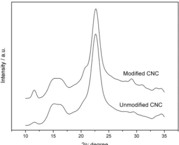
In addition to the shape and size of the nanoparticles, the crys-tal structure of the modified nanocryscrys-tals can be used to evaluate their structural integrity.41 X Ray diffraction measurements were performed to determine whether the chemical modification altered the crystallinity of the nanocrystals. The unmodified CNC and the chemically modified CNC presented the same X-ray diffraction pattern (Figure 4). The three main peaks at 2θ close to 15°, 17°, and 22.6° were observed for both samples and are characteristic of the X-ray diffraction peaks for cellulose I.42,43 For purposes of comparison, we estimated the crystallinity indexes of the different CNC using the intensity ratio equation (I002 - IAM)/I002 x 100.
44 In this
equation, I002 is the intensity value of the peak at 2θ close to 23°, which represents the crystalline material, and IAM is the intensity value at 2θ close to 18°, which represents the amorphous material. The obtained values for the crystallinity indexes were 86% and 84% for u-CNC and m-CNC, respectively. Similar values of crystallinity for cellulose nanocrystals were found by different authors.45-47 These results showed that, although the lateral size of the nanocrystals was considerably modified by the chemical modification (TEM images), the crystallinity of the nanoparticles remained almost unchanged.
Qualitative evidence for modification of the hydrophylic na-ture of the CNC after chemical modification can be obtained from contact angle measurements. This technique allows for the estimation of the change in hydrophobicity of the nanoparticles, measuring the contact angle with two solvents presenting different polar and dispersion components. The contact angles and surface energy values obtained for the nanocrystals before and after chemical modification are summarized in Table 2. Measurements performed using a liquid with a predominant apolar character (diiodomethane) presented higher values of contact angle for the unmodified CNC (50°) than for the modified CNC (34°), indicating an increase in the hydrophobic character of the nanoparticles after chemical modification. The use of a more polar solvent (formamide), resulted in an increased contact angle was increased after chemical modification of the nanocrystals. It was not possible to measure the contact angle using water because the unmodified nanocrystals were dispersed when in contact with this solvent. Surface energy results show that the contribution of the polar part is considerably reduced when comparing u-CNC with m-CNC due to the insertion of nonpolar groups on the surface of the nanocrystals, increasing their dispersive character.
Characterization of the nanocomposites
As mentioned, it was not possible to disperse the u-CNC within the PLLA matrix using the solvent casting method due to the hydrophilic character of the unmodified nanoparticles. During the preparation of the composites using u-CNC, a total phase separation and precipitation of the nanocrystals within the matrix took place. In contrast, using the chemically modified CNC, homogeneous nano-composite films were obtained.
Tensile mechanical tests were performed to determine whether the incorporation of m-CNC was effective to reinforce the PLLA polymer. Figure 5 shows the stress-strain curves for the neat PLLA and for the nanocomposites with 1 wt% and 5 wt% of m-CNC. The presence of m-CNC effectively increased the tensile strength by approximately 100% (from 11.7 MPa to 23.3 MPa) with the addition of only 1 wt% nanofiller. For the nanocomposite with 5 wt% m-CNC, the result was similar, increasing the tensile strength up to 24.4 MPa. We believe the values of the tensile strength of the nanocomposites, using 1 and 5 wt% of nanocrystals, was similar due to the aggregation of the cellulose nanoparticles that takes place when relatively high concentrations of the nanocrystals are used. Additionally, a remarkable increase in the elastic modulus was ob-served for both nanocomposites, from 0.88 GPa for the neat PLLA to 2.44 GPa and 2.36 GPa for PLLA-1% and PLLA-5%, respectively. Figure 3. TEM images of the unmodified cellulose nanocrystals (a) and of
the chemically modified cellulose nanocrystals (b)
Figure 4. X-ray diffraction patterns obtained for m-CNC and u-CNC
Table 2. Values of contact angle and surface energy for liquids tested for u-CNC and m-CNC
θ / ° Surface energy / mJ m -2
Diiodomethane Formamide γ γp γd
u-CNC 50.0 27.8 55.4 32.8 22.6
The effective reinforcement effect of the m-CNC in PLLA bio-polymer indicates the formation of a suitable percolation network due to a good dispersion of the modified nanocrystals within the matrix. A considerable decrease in the elongation at break (from 4.5% for neat PLLA to 3.2% and 2.5%, for PLLA-1% and PLLA-5%, respectively) was observed and is due to the presence of a stiff and continu-ous network of cellulose nanofillers linked together by hydrogen bonding, which can hinder strain stretching.48-50 The decrease in the elongation at break has been described by other authors as an indication of good interaction between the polymer and cellulose nanocrystals.50,51
Hydrolytic degradation behavior of the nanocomposites
The weight loss of the nanocomposites as a function of time was studied in a phosphate-buffered solution. Given its similarity to bodily fluids, this solution is normally used to study the hydrolytic degradation behavior of materials for biomedical applications.
It is worth mentioning that the kinetics of the hydrolytic degrada-tion when comparing PDLLA amorphous polymer and PLLA semi-crystalline polymer is remarkably different. In a previous work52 we showed that PDLLA polymer can present approximately 80% of mass loss in 12 weeks in phosphate-buffered solution. Crystallinity is an important factor that influences the hydrolytic degradation, due to the different chain-packing arrangements of each polymer. Thus, the amorphous structure of the PDLLA allows a considerable amount of water to penetrate into its polymer matrix, resulting in a faster hydrolytic degradation than occurs in PLLA.10
Figure 6 shows the influence of m-CNC on the hydrolytic degradation behavior of PLLA. Whereas the neat PLLA presented approximately 10% mass loss in 16 weeks, the nanocomposites presented approximately 3% (PLLA-1%) and only 1% (PLLA-5%) mass loss in the same period. These results indicate that the modified nanocrystals delay the hydrolytic degradation of the PLLA.
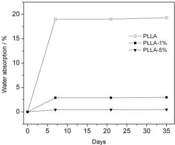
Considering that the first stage of hydrolytic degradation in PLLA occurs via nucleophilic attack by water on the carbonyl ester group, we measured the water absorption of the matrix and the nanocomposites in order to verify if the mechanism by which the modified nanocrystals delay the degradation rate was via in-creasing the water resistance of the biopolymer. We used distilled water to measure the water uptake because the degradation occurs more slowly in this medium than in a phosphate buffer. Had we used the latter medium, we might have caused weight loss in
the sample due to the degradation process, offsetting the effects of water absorption. Figure 7 shows the water absorption for the neat PLLA and the nanocomposites as a function of time. The neat PLLA absorbs approximately 20% of its mass in only one week, whereas for the nanocomposite with only 1% of m-CNC, the ab-sorption of water decreases to approximately 3% of polymer mass in the same period of time. The nanocomposite with 5% m-CNC, did not demonstrate any water absorption after 35 days. This result clearly demonstrates that the hydrophobic properties of the esterified nanocrystals hinder water absorption, acting as physical barriers for permeation of water within the polymer matrix and delaying the degradation of the polymer.
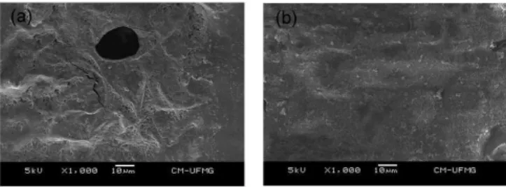
The neat PLLA and PLLA/m-CNC samples were characterized by SEM analysis before and after degradation in the phosphate buffer. SEM images investigation of the surface and of the cryofracture of the nanocomposites (not shown here) did not show the presence of large agglomerates of the nanocrystals for all magnitudes investigated. This indicates that the CNC were well dispersed in the polymer matrix. Figure 8 shows images obtained from the surfaces of the neat PLLA and the composite PLLA-1%. The images show that the m-CNC Figure 5. Stress-strain curve for the neat PLLA and the nanocomposites
Figure 6. Mass remaining of the neat PLLA, PLLA-1% and PLLA-5% as a function of degradation time
induced a delay in the polymer hydrolytic degradation. Whereas the image obtained for the neat PLLA after degradation (Figure 8a) shows the presence of relatively large pores (Figure 8a shows a pore with 20 µm of diameter approximately), the composite PLLA-1% (Figure 8b) showed no pores after the degradation period. SEM morphology obtained for the composite PLLA-5% after degradation was similar to that obtained for PLLA-1%.
All these results corroborate to the conclusion that the modi-fied cellulose nanocrystals used in this work have contributed not only to enhance the mechanical performance of the biopolymer but also to delay substantially the hydrolytic degradation of the PLLA. In this way, the m-CNCs prepared here can be used to control (fine-tune) the degradation of this polylactide according to the particular application of this biopolymer in moist or physi-ological environments.
CONCLUSIONS
We prepare and characterized bionanocomposites based on PLLA and esterified cellulose nanocrystals by simple solution casting method. The m-CNC were prepared by a method in which the hydrolysis of cellulose was performed simultaneously with the esterification of hydroxyl groups on the surface of the nanocrystals. In the prepared m-CNC sample, approximately 5% of hydroxyl cellulose groups were substituted by the acid residue, resulting in more hydrophobic nanoparticles than the unmodified one. The nanocomposites prepared with m-CNC showed better mechanical properties than the neat PLLA. For the nanocomposite with 1 wt% m-CNC, the tensile strength and the elastic modulus increased by approximately 100% and 178%, respectively. Besides enhance the mechanical performance, we describe here the possibility of use the m-CNCs to control (fine-tune) the degradation of this biopolymer in moist environment. The hydrolytic degradation study of the nano-composites demonstrated that a low concentration of m-CNC (1 wt%) in PLLA can lead to a remarkable decrease in the degradation rate of the biopolymer. This effect is due to the hydrophobic properties of the modified nanocrystals incorporated into the polymer matrix which hinder water absorption by the polymer matrix. The results described here can find applications to enhance the mechanical prop-erties and to fine-tune the degradation rate of the best-represented biodegradable aliphatic polyester on the market in moist or physi-ological environments.
ACKNOWLEDGMENTS
The authors thank CAPES (Nanobiotec - EDT Nº 04/2008), Fapemig (EDT N° 01/2013) and Pró-reitoria de Pesquisa-UFMG for their financial support. V. Mano thanks CAPES for the financial support (Proc. BEX 0249/13). Centro de Microscopia-UFMG is gratefully acknowledged for the TEM and SEM images.
REFERENCES
1. Bendix, D.; Polym. Degrad. Stab. 1998, 59, 129. 2. Lunt, J.; Polym. Degrad. Stab. 1998,59, 145.
3. Goffin, A-L.; Raquez, J-M.; Duquesne, E.; Siqueira, G.; Habibi, Y.; Dufresne, A.; Biomacromolecules 2011, 12, 2456.
4. Hu, Y.; Liu, Y.; Qi, X.; Liu, P.; Fan, Z.; Li, S.; Polym. Int. 2012,61, 74.
5. Grabow, N.; Schlun, M.; Sternberg, K.; Hakansson, N.; Kramer, S.; Schmitz, K. P.; J. Biomech. Eng. 2005, 127,25.
6. Ogata, N.; Jimenez, G.; Kawai, H.; Ogihara, T.; J. Polym. Sci. Polym. Phys. 1997,35, 389.
7. Cai, H.; Dave, V.; Gross, R. A.; McCarthy. S. P.; J. Polym. Sci. Polym. Phys. 1996,34, 2701.
8. Wong, Y. S.; Venkatraman, S. S.; Acta Mater. 2010, 58,49.
9. Beiser, I. H.; Kanat, I. O.; Journal of the American Podiatric Medical Association 1990, 80, 72.
10. Alexis, F.; Venkatraman, S.; Rath, S. K.; Gan, L-H.; J. Appl. Polym. Sci.
2006, 102,3111.
11. Chouzouri, G.; Xanthos, M.; J. Plast. Film Sheeting 2007, 23, 19. 12. Shi, Q. F.; Zhou, C. J.; Yue, Y. Y.; Guo, W. H.; Wu, Y. Q.; Wu,
Q. L.; Carbohyd. Polym. 2012, 90, 301.
13. Fukushima, K.; Abbate, C.; Tabuani, D.; Gennari, M.; Camino, G.; Polym. Degrad. Stab. 2009, 94, 1646.
14. Chen, L.; Xie, Z.; Zhuang, X.; Chen, X.; Jing, X.; Carbohyd. Polym.
2008, 72, 342.
15. Moraes, C. M.; de Matos, A. P.; de Paula, E.; Rosa, A. H.; Fraceto, L. F.; Mat. Sci. Eng. B 2009, 165,243.
16. Tsuji, H.; Mizuno, A.; Ikada, Y.; J. Appl. Polym. Sci. 1998, 70, 2259. 17. Santana, V. T.; Goncalves, S. P. C.; Agnelli, J. A. M.;
Martins-Franchetti, S. M.; J. Appl. Polym. Sci. 2012, 125, 536.
18. Fukushima, K.; Tabuani, D.; Abbate, C.; Arena, M.; Ferreri, L.; Polym. Degrad. Stab. 2010, 95, 2049.
19. He, L.; Sun, J.; Wang, X.; Fan, X.; Zhao, Q.; Cai, L.; Mater. Chem. Phys. 2012, 134, 1059.
20. Goffin, A. L.; Raquez, J. M.; Duquesne, E.; Siqueira, G.; Habibi, Y.; Dufresne, A.; Polymer 2011, 52, 1532.
21. Labet, M.; Thielemans, W.; Cellulose 2011, 18, 607.
22. de Mesquita, J. P.; Donnici, C. L.; Pereira, F. V.; Biomacromolecules
2010, 11, 473.
23. Siqueira, G.; Bras, J.; Dufresne, A.; Biomacromolecules 2009, 10, 425.
24. Eichhorn, S. J.; Dufresne, A.; Aranguren, M.; Marcovich, N. E.; Capadona, J. R.; J. Mater. Sci. 2010, 45, 1.
25. Klemm, D.; Kramer, F.; Moritz, S.; Lindstrom, T.; Ankerfors, M.; Gray, D.; Angew. Chem. Int. Ed. 2011, 50, 5438.
26. Brito, B. S. L.; Pereira, F. V.; Putaux, J-L.; Jean, B.; Cellulose 2012, 19, 1527.
27. de Mesquita, J. P.; Patricio, P. S.; Donnici, C. L.; Petri, D. F. S.; de Oliveira, L. C. A.; Pereira, F. V.; Soft Matter 2011, 7, 4405. 28. Samir, M.; Alloin, F.; Dufresne, A.; Biomacromolecules 2005, 6, 612. 29. Thielemans, W.; Belgacem, M. N.; Dufresne, A.; Langmuir 2006, 22,
4804.
30. Namazi, H.; Dadkhah, A.; Carbohyd. Polym. 2010, 79, 731.
31. Labet, M.; Thielemans, W.; Dufresne, A.; Biomacromolecules 2007, 8, 2916.
32. Habibi, Y.; Dufresne, A.; Biomacromolecules 2008, 9, 1974.
33. Habibi, Y.; Goffin, A-L.; Schiltz, N.; Duquesne, E.; Dubois, P.; Dufresne A.; J. Mater. Chem. 2008, 18, 5002.
34. Morandi, G.; Heath, L.; Thielemans, W.; Langmuir 2009, 25, 8280. 35. Nair, K. G.; Dufresne, A.; Gandini, A.; Belgacem, M. N.;
Bio-macromolecules 2003, 4, 1835.
36. Braun, B.; Dorgan, J. R.; Biomacromolecules 2009, 10, 334. Figure 8 . SEM images of the neat PLLA (a) and PLLA-1% (b) after 8
37. Lin, N.; Chen, G.; Huang, J.; Dufresne, A.; Chang, P. R.; J. Appl. Polym. Sci. 2009, 113, 3417.
38. Siqueira, G.; Bras, J.; Dufresne, A.; Langmuir 2010, 26, 402. 39. de Mesquita, J. P.; Donnici, C. L.; Teixeira, I. F.; Pereira, F. V.;
Car-bohyd. Polym. 2012, 90, 210.
40. Buschlediller, G.; Zeronian, S. H.; J. Appl. Polym. Sci. 1992, 45, 967. 41. Habibi, Y.; Lucia, L. A.; Rojas, O. J.; Chem. Rev. 2010, 110, 3479. 42. Borysiak, S.; Garbarczyk, J.; Fibres Text. East. Eur. 2003, 11, 104. 43. Sun, Y.; Lin, L.; Pang, C.; Deng, H.; Peng, H.; Li, J.; Energ. Fuel. 2007,
21,2386.
44. Moran, J. I.; Alvarez, V. A.; Cyras, V. P.; Vazquez, A.; Cellulose 2008, 15, 149.
45. Teixeira, E. M.; Correa, A. C.; Manzoli, A.; Leite, F. L.; de Oliveira, C. R.; Capparelli, L. H.; Cellulose 2010, 17, 595.
46. Cherian, B. M.; Pothan, L. A.; Nguyen-Chung, T.; Mennig, G.; Kot-taisamy, M.; Thomas, S. A.; J. Agr. Food Chem. 2008, 56, 5617. 47. Martinez-Sanz, M.; Lopez-Rubio, A.; Lagaron, J. M.; Carbohyd. Polym.
2011, 85,228.
48. Lu, Y.; Weng, L.; Cao, X.; Carbohyd. Polym. 2006, 63, 198.
49. Siqueira, G.; Abdillahi, H.; Bras, J.; Dufresne, A.; Cellulose 2010, 17, 289.
50. Azeredo, H. M. C.; Mattoso, L. H. C.; Wood, D.; Williams, T. G.; Avena-Bustillos, R. J.; McHugh, T. H.; J. Food Sci. 2009, 74, N31. 51. da Silva, J. B. A.; Pereira, F. V.; Druzian, J. I.; J. Food Sci. 2012, 77,
N14.