T
ABSTRACT
A COMPUTATIONAL METHOD FOR RECORDING AND
ANALYSIS OF MANDIBULAR MOVEMENTS
Alan Petrônio PINHEIRO1, Adriano O. ANDRADE2 , Adriano A. PEREIRA3, Douglas BELLOMO4
1- MSc, PhD Student in Biomedical Engineering, Laboratory of Biomedical Engineering, Federal University of Uberlândia, Uberlândia, MG, Brazil.
2- PhD, Full Professor, Laboratory of Biomedical Engineering; Federal University of Uberlândia, Uberlândia,MG, Brazil. 3- DSc, Full Professor, Laboratory of Biomedical Engineering; Federal University of Uberlândia, Uberlândia,MG, Brazil. 4- DDS, PhD Student, Laboratory of Biomedical Engineering; Federal University of Uberlândia, Uberlândia,MG, Brazil.
Corresponding address: Dr. Alan Petrônio - Av. João Naves de Ávila, 2121, bloco 1E, Campus Santa Mônica - 38400-902 - Uberlândia, MG, Brasil - Phone/Fax: +55-34-3239-4771 - e-mail: [email protected]
Received: February 14, 2008 - Modification: April 16, 2008 - Accepted: May 28, 2008
his study proposed the development of a new clinical tool capable of quantifying the movements of opening-closing, protrusion and laterotrusion of the mandible. These movements are important for the clinical evaluation of the temporomandibular function and muscles involved in mastication. Unlike current commercial systems, the proposed system employs a low-cost video camera and a computer program that is used for reconstructing the trajectory of a reflective marker that is fixed on the mandible. In order to illustrate the clinical application of this tool, a clinical experiment consisting on the evaluation of the mandibular movements of 12 subjects was conducted. The results of this study were compatible with those found in the literature with the advantage of using a low cost, simple, non-invasive, and flexible tool customized for the needs of the practical clinic.
Key words: Mandibular movements. Digital measurement. Temporomandibular joint. Malocclusion.
INTRODUCTION
In comparison to other musculoskeletal systems of the human body, the mandible presents special characteristics that make it an interesting object of study in the field of biomechanical movement. It is capable of performing a great variety of precise coordinated movements to perform functions such as chewing and speech. However, there are many problems associated with the mandible and thus it is necessary to develop non-invasive means to evaluate the dysfunctions affecting this complex system. The study of mandibular movements is of key importance in clinical analysis of mastication16.
The study of movements is an important tool used in biomechanics and it is employed in the analysis of movements in both two-dimensional (2D) and three-dimensional (3D) spaces. The analysis of mandibular movements is specifically good at providing important parameters for evaluation of the temporomandibular joint (TMJ) function as well as for the determination of the state of muscles involved in mastication14. In particular, three
movements are investigated in the evaluation of the mandibular musculoskeletal system: (1) opening-closing, (2) protrusion and (3) laterotrusion. These are all specific
movements for the functional evaluation of the mandible (MFEM).
A number of methods have been employed to measure mandibular movements. Many of them are based on the use of recording instruments that usually employ sensors fixed on the mandible12,19, like (1) ultra-sound30, (2)
accelerometers18, (3) electromagnetic fields31, (4) video
fluoroscopy32 and (5) optoelectronic devices26. However,
none of these methods is ideal for recording mandibular movements. For instance, systems that use ultra-sound are inaccurate and extremely vulnerable to the environmental conditions; those based on accelerometers do not produce stable recordings of the static position of the mandible; electromagnetic fields are very sensitive to the presence of metal within the environment; video-fluoroscopy exposes patients to ionizing radiation; optoelectronic devices usually demand rigid laboratorial conditions, for example, well-controlled lightening and a complex camera setting. Even so, the optoelectronic method is the most commonly used33,34. It works digitalizing the movement by using video
laboratories and clinics. This is because the current systems: a) use sensors, which are of large size, and frequently based on LEDs (light emission diode)2,6,12,18,31. The use of
LEDs restrict the movement because of wires that connect them to the power source;
b) have a high cost, specially due to the large number of required cameras and the system complexity (e.g.: most systems only works in a highly controlled environment);
It is important to note that many commercial systems that use video cameras for recording movement use at least two cameras for reconstruction of the trajectory of the mandible in the 3D space26. This is one of the reasons why
these systems are complex and costly. In view of this, some studies have investigated the possibility of devising alternative and simpler systems. For instance, some results12,14,19,30,33 demonstrate that although the MEFM occur
three-dimensionally, their main displacement components are produced on a two-dimensional plane. So, decomposition of the MFEM on the single view plane appears as an interesting strategy to facilitate the interpretation and visualization of the movement. Furthermore, the use of a single camera allows for the cost reduction and simplification of the assessment of the mandibular movement.
This developed and assessed a low-cost system capable of recording and reconstructing mandibular movements automatically and providing a simplified way to quantify mandibular trajectory. The system is composed of a single conventional video camera and a computer program. The function of the program is to analyze video footage by means of computer-assisted techniques that provide accuracy, reliability and robustness to the measurement of mandibular movement. In order to illustrate the clinical application of this tool, a clinical experiment consisting on the evaluation of the mandibular movements of 12 subjects was conducted
MATERIAL AND METHODS
Movement Measurement
Measurement of mandibular movement is carried out with the aid of a marker (sensor), which is fixed to the mandible. Using a video camera, the maker movement is recorded and then processed by a computer program capable of detecting the marker on the images and reconstructing its trajectory graphically in the 2D space.
A second marker, identical to the one used on the mandible, must be fixed to the head in order to estimate its movements. As mandibular movements are actually a combination of mandibular and head movements26, is
necessary to compensate head movement. This compensation is made by subtracting the movement of the marker fixed to the mandible from the movement of the marker on the head. Positioning of both markers is illustrated in Figure 3a.
Protocol for Recording Mandibular Movements Prior to data collection, the subjects signed an informed consent form approved by the local Research Ethics
Committee. The subjects were instructed to sit down on a dental chair, with the trunk positioned approximately 90º with
relation to the horizontal plane (floor). The camera was positioned at a distance of approximately 600 mm from the subject’s face (Figure 1a). Prior to data collection, the markers were fixed to the mouth and head (Figure 3a).
The marker consisted of a 10-mm–diameter plastic sphere covered14 by a reflective material (Scotchlite™ High Gain
Reflective Sheeting 7610, 3M, St. Paul, MN, USA) that reflects the majority of the light that reaches it with minimal dispersion. The use of this material ensures that the marker will be highlighted on the scene due to its contrast. The marker is fixed to the mandible with a metallic support, which is set in the mouth and does not obstruct the natural movement of the mandible. The base of the support is carefully fixed between the lower lip and the mandibular incisors, and is designed in such a way to reproduce the shape of the gingiva, firmly fixing the support. Figure 1b illustrates the marker as well as its fixing support.
The marker is fixed to the head with Velcro tape. This marker records the head movements when the head moves up, down, right or left. In order to avoid any type of bending movements, the head should be firmly held by a head support. This is important because if the head is rotated on an axis close to the marker fixed to the head distortions in the measurements may occur.
After the two markers are fixed, the camera should be positioned to the sagittal plane at the first instance. The lateral opening-closing and laterotrusion movements will be recorded on this plane. During the first seconds of shooting, a rigid plastic object, known as a calibration object, is placed into the subject’s mouth and fixed between the teeth. Figure 2 illustrates the calibration objects used for recordings on the sagittal and coronal planes. These objects are used to calibrate the camera and to reconstruct the trajectory of movement during one of the steps of the program.
Shortly after acquiring some image frames from the calibrator in the subject’s mouth, the object is removed and the subject undertakes the MFEM with only the mandible and head markers in position. If calibration object is moved in relation to the marker, no compensation is necessary, as it does not alter in any way the form or amplitude of the movement (only the referential Cartesian is altered). Finally, all camera calibration procedures are repeated for the recordings made on the coronal plane where the laterotrusion and frontal opening-closing movements are made.
Data Processing
The movement measuring procedure is carried out following the sequence of steps that will estimate the position of the two markers along the sequence of the film. After the analysis of the whole video, the trajectory of the marker is reconstructed, compensation for the movement is carried out, and the collected data are filtered (smoothed) and analyzed statistically. Figure 3 illustrates the whole process and its main steps.
is transferred to the computer and decomposed into images or frames. These images will be processed one by one by the tracking step. Before this, the user should select an image, which had been extracted from the video, for use in the camera calibration step. In this image, the calibration object should be visible and placed in the subject’s mouth. Camera calibration is a widely used procedure in computer vision8 for extraction of metric information from
the scene from where the images will be taken. It is executed by the observation of a calibration object with a known geometry. In simple terms, the process defines a mathematical correspondence between the coordinates from the image plane (given in pixels) and the real space coordinates (given in meters) where the movement takes place. The problem is
thus to calculate some of the mathematical coefficients that permit this conversion of spaces. Direct linear transformation algorithm27 is employed for this purpose. In order to
determine this relationship, some known coordinate points are used from the calibration object. The program will find these points on the image of the calibration object and compare them to the real values, measured in meters. The coefficients are calculated after comparisons are done. They will be used in the reconstruction step for the conversion of pixels into meters as well as to compensate some image distortions15.
After calibration, the markers should be found along the sequence of images extracted from the video. To determine their trajectory, it is necessary to identify and track their
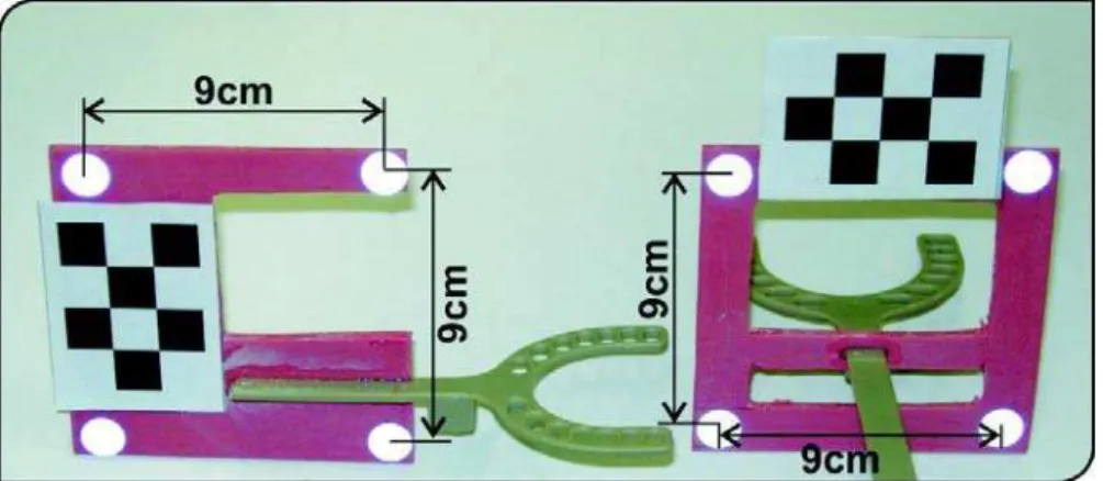
FIGURE 2- Calibration objects used in the sagittal (left) and coronal (right) views, respectively. They have a base that is
placed between the teeth of the subject
FIGURE 3- Schematic diagram for data processing. (a) Video acquisition with the markers; (b) calibration using the calibration
object; (c) tracking the markers on each video frame; (d) reconstruction of the marker’s coordinates and smoothing of movement traced (noise removal); (e) graphical and statistical analyses of the movement
FIGURE 1- (a) Recording of mandibular movements of a subject (frontal plane). The marker support was rigidly fixed using
position along the sequence of images. In this way, the program should automatically extract the regions from the image that correspond to the markers from the original scene and calculate the coordinates of their respective centers35.
After the tracking step, the coordinates for the center of the markers are obtained. As these coordinates are expressed in pixels, it is necessary convert them into the International System of Units, and also to compensate image distortions. This is carried out in the reconstruction step. The mathematical coefficients calculated during the calibration step are used in this stage.
Briefly, the reconstruction step consists of the multiplication of the coordinates from the center of the marker of the image (in pixels), by the coefficients calculated in the calibration step. The results of this operation are the coordinates of the movement from the marker (meters). By the use of these coordinates, the curve of the trace of the movement is determined. In sequence, this curve should go through a smoothing process. This process attenuates the noise that is intrinsic to this technique by filtering procedures. The filter used in this project was a Butterworth with 2 poles and a default cut-off frequency of 8 Hz10.
According to Miles23, the mandible voluntary movements
together with the tremor movements can reach a frequency of 6-7 Hz. By means of a filter, noise with frequency superior to 8 Hz is suppressed, giving a smoother appearance to the movement trace.
After the processing stages described above a statistical analysis is performed with the collected data.
Statistical Analysis of Movement
A single movement cycle is not sufficient for evaluation of the masticatory functions. Several samples of a type of movement are obtained in order to define its template (or average). Therefore, the proposed system is capable of calculating the average movement from a set of cycles carried out in sequence, by the use of a statistical technique called Bootstrap11. This same technique is also capable of
calculating the confidence interval for the mean, which is of 95% in the system.
Clinical Application, Accuracy and Precision In order to evaluate the developed system, two types of tests were carried out. The first test estimated its precision and accuracy based on a classical experiment in the area36.
Note that, in practice, this is the sole way of evaluating the reliability of the system.
This experiment is carried out using a rigid bar that has two markers fixed to it at a distance of 50 mm between them. The bar is joined to a motor that turns only on the vertical plane. The camera used in the experiment (DCR-HC28, Sony, Japan) was placed at 600 mm from the movement plane of the bar in an environment with low light control. In order to estimate the accuracy and precision of the measurements, the position of each marker, and the distance between them for each video frame, were calculated. The estimated distance values were then compared with the known value (true value) of 50 mm. The precision was obtained by means of the
standard deviation of the distance between the markers. During the tests, no filtering was performed so that the characteristics of the system became more evident.
The aim of the second test was to investigate the potential application of the system to the practical clinic. For such purpose, 12 subjects were selected to participate in the study (6 men and 6 women; mean age = 27 ± 9 years old). Five subjects presented malocclusion accompanied by TMJ dysfunction. The other subjects presented no masticatory problems or dysfunction. Diagnosis was based on absence of signs and symptoms of temporomandibular disease, as muscular pain, TMJ sounds (clicking, crepitus or tinnitus) and mandibular movements limitations. Three experienced professionals examined the individuals independently.
Before shooting, each subject was instructed to carry out the MFEM. Instructions and demonstrations were given for each movement as well as the opportunity to practice them. A professional from the area selected the start and end of each cycle of movements in the program. Repeated cycles were used to calculate the mean movement. During the tests, 64 opening-closing, 59 protrusion and 54 lateral movement cycles were processed.
In order to assess the clinical reliability of the method, a comparison among the trajectories of healthy subjects was carried out. For this, the correlation between trajectories and the mean correlation was estimated. This correlation was calculated by using the MatLab program (MathWorks Inc., Sherborn, MA, USA).
RESULTS
Analysis of Precision and Accuracy
The results obtained from the first test (analysis of the trajectory of a rigid bar joined to a motor) are presented in Table 1. They are estimates taken from 120 samples (repetitions). The accuracy, calculated as the distance between the true value and the estimated one, was of 99.2%. Therefore, the mean error was of 0.4 mm. The precision, given by the standard deviation was 99.4%, corresponding to 0.3 mm. The high values obtained for the accuracy and precision of the system confirms its reliability.
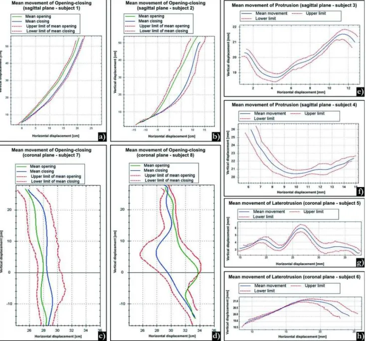
Analysis of the Clinical Reliability of the System Figure 4 shows typical results obtained from a clinical test that evaluated mandibular movements in a group of subjects. In these graphs the mandibular trajectory of 8 different subjects are provided. Four subjects (1, 3, 5, 7) were judged as healthy, whereas the others (2, 4, 6, 8) presented masticatory dysfunction. The confidence interval for the mean movement is presented as the “upper limit” and “lower limit” on the graphs.
studied in the coronal plane (Figure 4c), the opening and closing trajectories are also close, with a maximal horizontal deviation of 2 mm. This fact highlights a balance between muscles acting upwards and downwards. Same results were not observed with the pathological movement of the subject 8 (Figure 4d), which presents irregularities in both trajectories and a large horizontal movement component (6 mm). Some researchers3 have reported that this horizontal displacement
disparity may be a consequence of lack of coordination of the muscles responsible for closing and opening movements.
In the laterotrusion movement of a healthy subject (Figure 4g), a balance between the left and right sides of the
Accuracy and precision Error
True value 50.0 mm
Estimated (mean) 49.6 mm 0.8%
Standard deviation 0.3 mm 0.6%
Maximum error (+) 51.1 mm 2.2%
Maximum error ( - ) 49.0 mm 2.0%
TABLE 1- Accuracy and precision of the experiments
FIGURE 4- Graphs showing the evaluation of the functional movements of the mandible from 8 subjects. (a) Normal
movement is obtained. This highlights a symmetric trajectory, which is not observed in subjects that have TMD symptoms, as illustrated in Figure 4h. The results shown in this figure indicate that subject 6 has larger movement amplitude at the left side determined by a superior activity of the left lateral pterygoid muscle caused by a unilateral chewing habit. Individuals that present this pattern of mastication are prone to suffer from masticatory disorders1,20.
The protrusion mandibular movement of a healthy subject (Figure 4e) starts with a mandibular downward movement guided by sliding of the mandible head through the posterior wall of the articular eminence and the incisor edge of lower incisors across the lingual surface of upper incisors till the border-to-border position with 2 mm upward and 3 mm forward mandibular displacement. Following this initial movement, there is a 3 mm upward and 9 mm forward mandibular displacement and, at the end of the movement, a small curve is observed. In the pathologic subject (Figure 4f) with deep overbite, it is noted a pattern of malocclusion. A possible cause for this may be the large angle of rotation of the condyle in deep incisal overbite and a greater surface of gliding between incisors28.
During all tests involving subjects, the system was capable to automatically recognize the markers in every video frame. The mean time taken by the user to process five cycles of each movement was 6 min. The mathematical correlation calculated from 7 healthy subjects varied to each movement type assuming mean values of 0.93 to opening-closing in sagittal plane, 0.89 to opening-closing in frontal plane, 0.87 to protrusion and 0.81 to laterotrusion.
DISCUSSION
The results of the test that evaluated the mandibular movements from the 12 subjects are in agreement with those of previous investigations as to the form and amplitude5,6,22,24. The correlation values found when
comparing mandibular movements of healthy subjects indicate a good movement correlation and clinical reliability. For each of the three types of MFEM, an example of the movement of a healthy subject as well as a pathological movement was illustrated. In this last case, the graphics presented in Figure 4 confirms the cases of disc displacement of TMJ (subjects 2 and 8), deep bite (subject 4) and a right-sided chewing tendency (subject 6). The system presented makes available to the user two types of movement analysis: qualitative and quantitative. Although the qualitative analysis is of paramount importance to the clinical evaluation, the quantitative analysis is also relevant because the less subjective the evaluation, the better the assessment of the patient’s need for treatment. In light of these findings, other resources of the system have been proved attractive, such as calculating the mean movement and its confidence interval. By the use of this interval, the examiner can analyze graphically the variability of the cycles used in the calculation of the mean movement.
In the other test, which evaluated precision and accuracy
of the system (Table 1), the values obtained for accuracy are in accordance to those calculated for other systems2,26,28,31. In these systems, the accuracy varied from
0.1 to 0.6 mm, whereas those obtained in the present study were 0.4 mm. The low standard deviation and the maximum error limits suggest a high repeatability and consistency in the measurements taken. The system was also successful in the automatic tracing of markers in environments where there was little light control. Note that the validation test employed in this study is a standard that has been widely used for validation of video based movement measuring systems4,7,9,17,21,25,29.
Experiments involving the analysis of intra and inter-examiner variability in the evaluation of masticatory functions were not found in the literature. However, it is expected that the margin of error involved in this type of analysis is reduced with the use of an automatic tool. in addition, the developed system is expected to permit that clinicians with varying levels of expertise be able to evaluate masticatory functions and TMJ with approximately the same amount of validity and reliability, regardless of their skills or previous experience.
CONCLUSIONS
This study presented a simple, low cost system, which used a standard camera to measure opening-closing, protrusion and laterotrusion movements on the sagittal and coronal planes. The devised system simplifies the movement measurement process, uses a small wireless sensor and has precision and accuracy compatible with commercial systems. The system does not require rigid laboratory conditions and can be used in clinical practice, appearing as a valuable means for increasing the representation and interpretation of the main movements for evaluation of the TMJ. However, it is important to emphasize that this research restricted its focus only to a few mandibular movements. Dentists and researchers from this area can use this tool for clinical analysis, in a way as to facilitate the interpretation and analysis of the mandibular movement in different planes. It can also aid in the diagnosis and treatment of problems associated with the masticatory system, allowing for a better following of the patient’s clinical evolution and monitoring of the TMJ dysfunction and malocclusions using quantitative and qualitative analyses. The proposed system is also an important apparatus for evaluation of physiological mechanisms involved in kinematics and dynamics of the mandible contributing to musculoskeletal modeling of the craniomandibular system.
ACKNOWLEDGEMENTS
REFERENCES
1 - Abdel-Aziz IY, Karara HM. Direct Linear transformation from comparator coordinates into object coordinates in close-range photogrammetry. In: Proceedings of the Symposium on Close-Range Photogrammetry; 1971 Jan; Falls Church. Falls Church: American Societ of Photogrammetry; 1971. p. 1-18.
2 - Abuzzahab FS, Lim TH, Harris GF. A method for covering surfaces of reflective gait markers. Gait Posture. 1995;3:264-5.
3 - Alonso FJ, Castilho JMD, Pintado P. Application of singular spectrum analysis to the smoothing of raw kinematic signals. J Biomech. 2005;38:1085-92.
4 - Buschang PH, Throckmorton GS, Travers KH, Hayasaki H. Incisor and mandibular condylar movements of young adult females during maximum protrusion and lateratrusion of the jaw. Arch Oral Biol. 2001;46:39-48.
5 - Castro JLG, Carnicer RM, Galisteo AM. Design and evaluation of a new three-dimensional motion capture system based on video. Gait Posture. 2006;24:126-9.
6 - Chen TC, Chung KL. An efficient randomized algorithm for detecting circles. Comput Vis Image Underst. 2001;83:172-91.
7 - Chiari L, Corece UD, Leardini A, Cappozzo A. Human movement analysis using stereophotogrammetry. Part 2: Instrumental errors. Gait Posture. 2005;21:197-211.
8 - Croce UD, Cappozzo A. A spot check for estimating stereophotogrammetric errors. Med. Biol Eng Comput. 2000;38:260-6.
9 - Darendeliler N, Dinçer M, Soylu R. The biomechanical relationship between incisor and condylar guidances in deep bite and normal cases. J Oral Rehabil. 2004;31:430-7.
10 - Ehara Y, Fujimoto H, Miyazaki S, Tanaka S, Yamamoto S. Comparison of the performance of 3D camera systems. Gait Posture. 1995;3:166-9.
11 - Everaert DG, Spaepen AJ, Wouters MJ. Measuring Small Linear Displacements with a three-dimensional video motion analysis system: determining its accuracy and precision. Arch Phys Med Rehabil. 1999;80:1082-9.
12 - Flavel SC, Nordstrom MA, Miles TS. A simple and inexpensive system for monitoring jaw movements in ambulatory humans. J Biomech. 2002;5:573-7.
13 - Fukui T, Tsuruta M, Murata K, Wakimoto Y, Tokiwa H, Kuwahara Y. Correlation between facial morphology, mouth opening ability, and condylar movement during opening-closing jaw movements in female adults with normal occlusion. Eur J Orthod. 2002;24:327-36.
14 - Gerstner GE, Fehrman J. Comparison of chin and jaw movements during gum chewing. J Prosthet Dent. 1999;81:179-85.
15 - Hamlet S, Faull J, Klein B, Aref A, Fontanesi J. Mastication and swallowing in patients with postirradiation xerostomia. Int J Radiat Oncol Biol Phys. 1997;37:789-96.
16 - Harper RP, Schneiderman E. Condylar movement and centric relation in patients with internal derangement of the temporomandibular joint. J Prosthet Dent. 1996;75:67-71.
17 - Hartley R, Zisserman A. Multiple view geometry in computer vision. Cambridge: Cambridge Press; 2003.
18- Holden JP, Selbie WS, Stanhope SJ. A proposed test to support the clinical movement analysis laboratory accreditation process. Gait Posture. 2003;17:205-13.
19- Kalaykova S, Naeije M, Slater JH. Is condylar position a predictor for functional signs of TMJ hypermobility? J Oral Rehabil. 2006;33:349-55.
20- Kimoto K, Tamaki K, Yoshino T, M. Toyoda, Celar AG. Correlation between elevator muscle activity and direction of sagittal closing pathway during unilateral chewing. J Oral Rehabil. 2002;29:430-5.
21- Koyano K, Ogawa T, Suetsugu T. The influence of canine guidance and condylar guidance on mandibular lateral movement. J Oral Rehabil. 1997;24:802-7.
22- Luzio KJ, Wyss UP, Costigan PA. A procedure to validate three-dimensional motion assessment systems. J Biomech. 1993;26:753-9.
23- Matsumura H, Tsukiyama Y, Koyano K. Analysis of sagittal condylar path inclination in consideration of Fischer´s angle. J Oral Rehabil. 2006;33:514-9.
24- Miles TS. Postural control of the human mandible. Arch Oral Biol. 2007; 2:347-52.
25- Naeije M. Local Kinematic and anthropometric factors related to the maximum mouth opening in healthy individuals. J Oral Rehabil. 2002;29:534-9.
26- Naeije M. Measurement of condylar motion: a plea for the use of the condylar kinematic centre. J Oral Rehabil. 2003;30:225-30.
27- Prinz JF. The cybermouse: a simple method describing the trajectory of the human mandible in three dimensions. J Biomech. 1997;30:643-5.
28- Reinhardt R, Tremel T, Wehrbein H, Reinhardt W. The unilateral chewing phenomenon, occlusion and TMD. Cranio. 2006;24:166-70.
29- Richards JG, The measurement of human motion: a comparison of commercially available systems. Hum Mov Sci. 1999;18:589-602.
30- Travers KH, Buschang PH, Hayasaki H, Throckmorton GS. Associations between incisor and mandibular condylar movements during maximum mouth opening in humans. Arch Oral Biol. 2000;45:267-75.
31- Wood WW. Medial pterygoid muscle activity during chewing and clenching. J Prosthet Dent. 1986;55:615-21.
32- Yang Y, Yatabe M, Soneda K. The relation of canine guidance with laterotrusive movements at the incisal point and the working side condyle. J Oral Rehabil. 2000;27:911-7.
33- Yoon HJ, Kristin DZ, Rebellato J, Kai-Nan A, Eugene EK. Kinematic study of the mandible using an electromagnetic tracking device and custom dental appliance: Introducing a new technique. J Biomech. 2006;39:2325-30.
34- Zafar H, Eriksson PO, Nordh E. Wireless optoelectronic recordings of mandibular and associated head-neck movements in man: a methodological study. J Oral Rehabil. 2000;27:227-38.
35- Zhang Z. A flexible new technique for camera calibration. IEEE Trans Pattern Anal Mach Intell. 2000;22:1330-4.