Journal of Applied Fluid Mechanics, Vol. 9, No. 1, pp. 33-42, 2016. Available online at www.jafmonline.net, ISSN 1735-3572, EISSN 1735-3645.
Film Cooling Effectiveness Enhancement Applying
another Jet in the Upstream Neighbor of the
Main Jet-Using LES Approach
M. R. Salimi
1, M. Ramezanizadeh
2†, M. Taeibi-Rahni
3and R. Farhadi-Azar
41
Aerospace Engineering Department, Sharif University of Technology, Tehran, Iran
2
Aerospace Engineering Department, Shahid Sattari Aeronautical University of Science & Technology, Tehran, Iran, Fax: +98-21-66693442
3
Aerospace Engineering Department, Sharif University of Technology, Tehran, Iran
4
Aerospace Engineering Department,Sharif University of Technology, Tehran, Iran
†Corresponding Author Email: [email protected]
(Received January 12, 2014; accepted December 19, 2014)
ABSTRACT
Flow hydrodynamic effects and film cooling effectiveness of placing a coolant port (upstream jet) just upstream of the main cooling jet were numerically investigated. The upstream jet was added such that the total cooling cross section (cross sections of the main and upstream jets) remains constant, in comparison to the case of ordinary cooling jet. The finite volume method and the unsteady SIMPLE algorithm on a multi-block non-uniform staggered grid arrangement were applied. The large eddy simulation (LES) approach with the one equation subgrid scale model was used. The jet to cross flow velocity ratio (for both of the main and the upstream jets) is 0.5 and the cross flow Reynolds number (based on the main jet parameters) is equal to 4700. The obtained results showed a significant improvement in the flow control capability and both centerline and span-wise averaged film cooling effectiveness applying the new cooling configuration. Effects of the upstream jet dimensions are also studied here. The obtained results showed that the span-wise width of the upstream jet has more essential influence on the cooling performance than that of its stream-wise width. Moreover, it is demonstrated that the film cooling performance could be enhanced even by applying an upstream jet which its temperature is as same as the cross-flow temperature, i.e. applying a hot upstream jet. Finally, it is shown that presence of the upstream jet decreases the stream-wise component of the velocity near the wall, which decreases the wall shear stress and the skin friction drag coefficient significantly.
Keywords: Film cooling effectiveness; Upstream jet; Large eddy simulation; Effectiveness enhancement; Drag reduction.
NOMENCLATURE
cf friction coefficient
P static pressure Pr Prandtle number Prt turbulence Prandtl
qi subgrid scale heat flux
Re Reynolds number Sc Sutherland’s constant
T static temperature Tr reference temperature
ui velocity vector u∞ inflow velosity
ρ density
µ dynamic viscosity µt turbulence viscosity
µr reference viscosity e number
Iτij subgrid-scale stress tensor
τw wall shear stress
1.
INTRODUCTION
Gas turbines are applied in various kinds of power plants such as power stations, airplanes, and submarines. Therefore, increasing the specific output work, cycle efficiency, or specific fuel
stresses in hot section parts in the gas and the steam turbines strongly limits this working temperature. A remedy, as stated by many researchers, is cooling the hot components by relatively cooler compressor air, through the state of the art of film cooling technique. In this method, cold air of the compressor leads to the high working temperature components and injects into the hot gas stream through a series of cooling holes. This cooling air then produces a protecting blanket on the surface and prevents direct attachment between the surfaces and the hot gases.
Film cooling has been extensively investigated in the literature, owing to three fields of flow coherent structures, controlling parameters of the flow, and cooling effectiveness enhancement. The film cooling effectiveness is a paprameter which shows the cooling performance. For instance, the adiabatic film cooling effectivnes defines as follow:
j c w c T T T T
(1)
where, Tc, Tj, and Tware cross flow, jet and local
wall temperature, respectively.
Haven and Kurosaka (1997), Ziefle and Kleiser (2013), and Yao and Maidi (2013) performed some experimental and numerical investigations considering the main coherent structures of the jet-into-cross flow problem and the film cooling as a special case. In those researches, efforts were focused to present some physical explanation of the main coherent flow structures such as the counter rotating vortex pairs (CRVPs), the horse shoe vortices (HSVs), and the ring vortices. In these studies, main flow structures and their influence on the cooling performance has been explained. Thus, these results have an illuminative role for the next researchers to improve the cooling performance by controlling the jet trajectory and its influenced region.
Another worth mentioned field of researches are those carried out to investigate the flow controlling parameters. For example, Rozati and Tafti (2008), Renze et al. (2006), and Ramezanizadeh et al. (2007), conducted some researches on the effects of mass, momentum and density ratios on the jet into cross flow penetration, flow mixing and film cooling effectiveness. Saumweber et al. (2003), studied the effects of turbulence level of the cross flow or the jet on the flow hydrodynamics and cooling performance. Gao et al. (2008), Ligrani and Jin (2013), and Dees et al. (2013), investigated the effects of surface conditions such as, surface roughness or curvature and cooling holes location (pressure side or suction side) on the global cooling characteristics. Ahn et al. (2007), Albert and Bogard (2013), and Diez et al. (2011) conducted some researches on the end wall condition, blades rotation, bulk flow pulsation, and flow contaminant deposition.
The last field includes such investigations performed to enhance the film cooling effectiveness. This category can be further divided into three subcategories. First; the researches which
have carried out to increase the cooling performance by improving the jet-into-cross flow geometry, including the cooling port size and shape and the jet exit surface configuration. Researches performed by Narzary and Han (2008), Albert and Bogard (2013), and An et al. (2013), are some examples. Second; researches have performed to improve the coolant distribution over the surface by varying the jet injection angle in different ways such as researches performed by Lee et al. (2002), Hung et al. (2009), Ligrani et al. (2013), and Acharya and Leedom (2013), Third; researches have done to increase the film cooling coverage and effectiveness by managing jets arrangement (jets locations relative to each other). Relatively, fewer researches on this area have been reported in the literature. Among these, researches of Ligrani and Ramsey (1997), Lu et al. (2007), Javadi et al. (2007), and Farhadi-Azar et al. (2011), are some samples.
Based on the author’s knowledge, a few studies have been performed on the film cooling problem dealing with the jet configurations. Thus, interactions between the main coherent structures of adjacent jets need more investigations. That is, it seems that interactions of the main vortical structures of adjacent jets may enhance the jet trajectory controllability and improve the film cooling efficiency. This motivated the present study to investigate the effects of introducing another cooling port just upstream of the main jet as a new jet configuration. Therefore, objectives of the present research is to investigate the main coherent structures, the film cooling efficiency, and the skin friction drag characteristics of this jet configuration, using the LES approach.
2.
GOVERNING EQUATIONS
In the Large Eddy Simulation (LES) approach, the large eddies are resolved directly, while the small ones are modeled applying a subgrid scale model. Resolving only the large eddies allows one to use a much coarser mesh and a larger time step, in comparison to the direct numerical simulation (DNS) approach. However, LES still requires a finer mesh and a smaller time step, comparing to those apply in the unsteady Reynolds averaged Navier-Stokes (URANS) approach (Tellervo 2006). Applying the spatial filter function to the continuity, momentum, and energy equations, we have:
0, i i u x
(2)
21
, Re
i j ij
i i
j i r j j j
u u
u P u
t x x x x x
(3)
. Re Pr i ii i i
u T
T K T
q
t x x x
(4)
where
is the dynamic viscosity of the gas and obtains from the Sutherland's law:3 / 2 . r c r r c T S T
T T S
(5)
and viscosity and Sc is the Sutherland’s constant (Ramezanizadeh 2007). The subgrid-scale stress tensor and the subgrid scale heat flux are defined as:
,ij u ui j u ui j
(6)
,i i i
q u T u T (7)
which require modeling. In this research, three different subgrid scale models, including the Smagorinsky model with wall function, the structure-function model (SFM) and the one equation model are implemented (Menon and Kim
1996). Also, the SGS heat flux vector,
q
i, ismodeled using a gradient-diffusion hypothesis as:
. Pr
t i
t j
T q
x
(8)
In which, Prt is the turbulent Prandtl number.
3.
PHYSICAL DOMAIN AND
NUMERICAL APPROACH
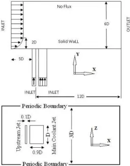
The simulations are performed considering two different physical domains based on the ordinary (single) jet and the new film-cooling configuration. In the upstream jet configuration, the film cooling can be enhanced by placing another injection hole just upstream of the main cooling hole, in order to modify the approaching boundary layer and its interaction with the cooling jet. This problem was investigated here using the LES approach. However, to compare the obtained results of the upstream jet configuration with that of the ordinary jet, the same injection area and the same amount of total coolant air were used. Other parameters, such as the size of the physical domain and the jet Reynolds number were taken to be as same as the ordinary film-cooling case (Fig.1).
Square cross section jets with a hydraulic diameter (jet width D) of 12.7 mm are considered which are normally injected into the cross flow. In order to examine the effects of the upstream jet dimensions on the flow hydrodynamics and cooling performance, both stream-wise and span-wise widths of the upstream jet were examined. That is, three different span-wise widths of 1D, 1.5D and 2D and four different stream-wise widths of 0.1D, 0.125D, 0.15D, and 0.2D were examined. Therefore, 12 upstream-to-main jets cross section ratios (from 0.1 to 0.4) were investigated. To compare the obtained results with that of the ordinary film cooling, same amount of total coolant air and same total cross-section area were applied. Therefore, increasing the upstream jet cross section decreases the main jet cross section. Also, the upstream jet and the main jet blowing ratios (
c c j
jV V
) are the same and equal to 0.5. Hence, as long as the total injection area is kept fix, the total coolant mass flux does not change. In the present research, the fluid density is equal to one for both jet and cross flow (jc1), thus the blowing
ratio is equal to the velocity ratio (
c
jV
V ).
Considering the experimental and computational research of Ajersch et al. (1995), the jet parameters are applied for the Non-dimensionalizaion purposes. The jet velocity and its Reynolds number were 5.5 m/s and 4700, respectively. Also, the jet to cross flow blowing ratio was considered 0.5, which is a more common value in the film cooling applications. At the cross flow inlet, the one-seventh power law profile was applied for the mean X velocity component (with a boundary layer thickness of 2D) and the other mean velocity components are set to zero. The isotropic synthetic fluctuations are applied to generate the inflow boundary condition at the cross flow inlet (Davidson 2007). The inlet velocity was considered to be uniform and the periodic boundary condition was used in the Z-direction to simulate the effects of the other jets.
Fig. 1. Schematic of the computational domain for the upstream jet configuration.
In order to solve the aforementioned governing equations, an in-house CFD code was developed by the authors based on the finite volume method. The unsteady SIMPLE algorithm were used to provide a coupling between the pressure and the velocity fields on staggered grid configuration. For the spatial discretization of the flux vectors, the QUICK algorithm was used along with the Crank-Nicholson scheme for the time discretization. The courant number (based on the smallest grid spacing and maximum velocity throughout the computational domain) was set to 0.01.
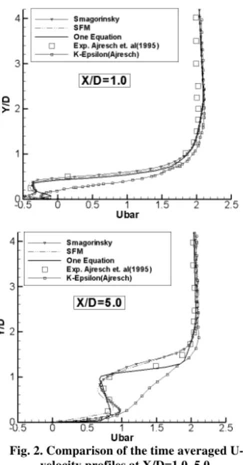
Ajersch et al. (1995). Thus, in Fig. 2, the time averaged streamwise velocity component (Ubar=U/VJet) predictions of the Smagorinsky model with wall function, SFM, and one equation model are compared to those of the Ajersch et al. (1995), at two stream-wise locations of X/D=1 and X/D=5, on the jet centerline (Z/D=0 plane). As shown in this figure, the one equation model showed better agreements with the experimental results. Therefore, this model was applied for the upstream jet configuration simulations.
Fig. 2. Comparison of the time averaged U-velocity profiles at X/D=1.0, 5.0.
The grid resolution study was performed applying three different grid arrangements. The total grid points used in each direction for the mean flow, the main jet, and the smaller upstream jet (0.1D in X-direction and 1D in Z-X-direction), are shown in Tables. 1, 2, and 3, respectively. The comparisons were performed using turbulent kinetic energy as a more sensitive flow variable (atX/Dj3). These comparisons are shown in Fig. 3. Based on these comparisons, the second grid was considered for the flow simulations.
4.
RESULTS
Here, it will be shown that how the flow hydrodynamics can be affected when another cooling jet introduces at the upstream of the main cooling jet. Also, effects of the upstream jet dimensions (the stream-wise width and the span-wise width of the jet in the X- and Z-directions,
respectively) on coolant distribution and film cooling effectiveness are investigated. In order to find the optimum dimensions of the upstream jet, various stream-wise and span-wise widths were examined, which are presented in this section.
Table 1 Number of grid points used in the main flow domain
Case NX NY NZ Total
1 90 40 25 90000
2 130 70 41 373100
3 150 85 48 612000
Table 2 Number of grid points used in the main jet channel
Case NX NY NZ Total
1 15 30 15 6750
2 22 45 22 21780
3 28 55 28 43120
Fig. 3. Grid resolution study.
4.1 Cooling Upstream Jet
Figure 4 shows the effects of the upstream jet on horseshoe vortices (HSV’s). From the literature, the blockage effects of the jet causes an adverse pressure gradient on the upstream cross flow boundary layer, which leads the cross flow boundary layer to diffuse laterally. Therefore, the vortices are stretched in the Z-direction in the cross flow boundary layer and form the front of the horseshoe vortices (Fig.4).These vortices are convected and tilted such that create the two branches of the characteristic horseshoe shape. Actually, these vortices separate the jet and the cross flow in the near field region of the jet. Thus, the wider HSV’s means wider cooling area in the near field of the jet. From this figure (Fig. 4), one can distinguish two major physical differences between characteristics of the new jet configuration flow and that of the ordinary single jet film cooling problem:
recirculation region. Then, these vortices convect downward and make another horseshoe vortex between the two branches of the upstream jet HSV’s.
Fig. 4. Comparison of the mean stream lines;a) Upstream jet configuration, b) Ordinary Film
colling (single jet).
2) As shown in Figs. 4 and 5, in the upstream jet configuration, size of the horseshoe vortices are comparable to the width of the upstream jet and they are much wider than that of the ordinary jet flow. These wider HSV’s cause more coolant distribution in the near field of the main jet.
Fig. 5. Comparison of the mean surface temperature contours; a) Upstream jet configuration, b) Ordinary Film cooling
(single jet).
The counter rotating vortex pairs (CRVP’s) are the main vortex structures of the jet into cross flow problem. The jet to cross flow momentum ratio (jet to cross flow velocity ratio in this work, due to the
flow incompressibility assumption) has a major effect on the CRVP’s strength. Introducing a new upstream cooling jet reduces the main jet velocity ratio (since the total coolant mass flow is kept constant), which causes an overall reduction in the jet to cross flow momentum ratio. Therefore, weaker CRVPs are created and less mixing occurs between the jet and the cross flow.
Figure 6 shows the mean temperature contours for the new jet configuration and the ordinary one in different XZ-planes. It could be observed that the new jet configuration develops slightly weaker CRVPs and hence, less mixing occurs among the coolant and the hot cross flow. This reduction in mixing strength increases the film cooling effectiveness.
a
b
Fig. 6. The mean temperature contours in various XZ planes; a) Upstream jet
configuration, b) Ordinary Film cooling (single jet).
In the upstream jet configuration, the main jet is not deflected directly by the cross flow until far away from the surface. Therefore, it may be expected that higher jet penetration through the cross flow occurs. But, division of the coolant gas between the two jets (the upstream and the main jets) causes a noticeable reduction in the effective momentum ratio. This effect overcomes the aforementioned expectation. Therefore, as shown in Fig. 6, the jet into cross flow penetration reduces in this new design.
in the near field region of the jet. However, in the new design, the coolant gas of the upstream jet mixes with the hot cross flow before moving toward this region. This phenomenon decreases the flow temperature and increases the film cooling effectiveness, especially in the vicinity of the jet downstream.
Downstream of the jet bending-over, a reverse flow zone develops, in which the hot cross flow mixes with the coolant gas from the sides. In this region, the flow is of wake character and is similar to the flow past a solid cylinder placed on the wall (Fig. 5). In the new design, as the upstream jet stream-wise width increases, this region is also increases. But, as discussed previously, the coolant gas from the upstream jet mixes with the hot cross flow and then flows toward this region. Therefore, in the upstream jet configuration, the gas in the wake region of the main jet is in a moderate temperature (and higher film cooling effectiveness achieves).
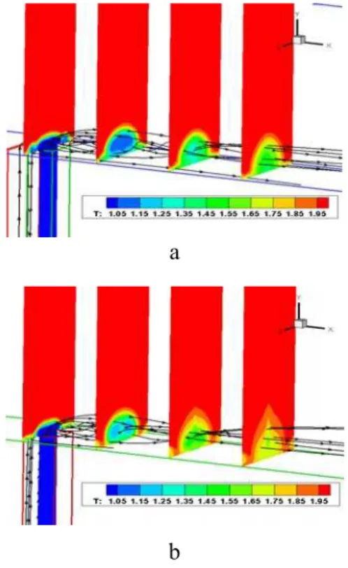
In Fig. 7, effects of upstream jet span-wise width on the mean temperature distribution over the surface are shown. From this figure, it is evident that increasing the span-wise width of the upstream jet increases the wake region and the cooling performance in near field zone of the main jet.
a
b
c
Fig 7. Mean temperature contours of the surface for the upstream jet configuration at different
span-wise width; a) 1D, b) 1.5D, and c) 2D.
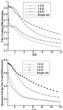
The spanwise averaged and centerline film cooling effectiveness profiles for three different span-wise widths of the upstream jet (while the stream-wise
width is 0.1D) are compared with those of the ordinary film cooling problem in Fig. 8. It’s obvious that increasing the span-wise width of the upstream jet, both the centerline and the span-wise averaged film cooling effectiveness increase. Therefore, the upstream jet span-wise width has a major effect on uniform distribution of the coolant gas over the surface. Moreover, this figure shows that the cooling performance in far field region of the cooling jet, in comparison to the near field region (X/D<4), is more affected by increasing the span-wise width of the upstream jet, especially for span-wise widths of 1.5D and 2D.
Fig 8. Mean film cooling effectiveness profiles for different span-wise widths of the upstream jet.
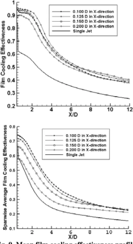
Fig. 9. Mean film cooling effectiveness profiles for different stream-wise widths of the
upstream jet.
4.2 Hot Upstream Jet
It may be judged that replacing two cooling ports instead of single one (with any favorable configuration) increases the film cooling performance due to extending the cooling jet cross section in the span-wise direction. That is, placing another cooling port at upstream of the main jet has no significant advantage over any other probable configuration. However, we believe that applying the upstream jet configuration alters the flow hydrodynamics and controls the flow coherent structures. Therefore, in this section (for the first time in film cooling history) we show that the film cooling performance could be enhanced even by applying an upstream jet flow which its temperature is as same as the cross-flow temperature, i.e. applying a hot upstream jet.
Figure 10 shows the mean temperature contours of the surface for both the hot upstream jet configuration (span-wise width of 2D and stream-wise width of 0.15D) and the ordinary jet case. It could be observed that in the hot upstream jet configuration, the coolant gas of the main jet distributes more uniform over the surface. As mentioned in the previous section, presence of the upstream jet causes wider cooling region at the downstream of the main jet (especially in the near field region).
Figure 11 shows the centerline and span-wise averaged film cooling effectiveness for the hot upstream jet configuration and the ordinary jet cases. Simulations were performed for the
span-wise width of 1.5D and three different stream-span-wise widths of 0.1D, 0.15D and 0.2D. Although a hot upstream jet was utilized, as shown in this figure, both the centerline and span-wise averaged effectiveness in the new configuration is about 50% higher than that of the ordinary cooling jet case. Also, this figure shows that by increasing the upstream jet stream-wise width, both of the centerline and span-wise averaged effectiveness increase.
a
b
Fig. 10. Mean temperature contours of the surface; a) Ordinary film cooling (single jet), b)
Hot upstream jet configuration.
Fig. 11. Mean film cooling effectiveness profiles for different stream-wise widths of the hot
4.3 Effect on Skin Fiction Drag
The skin friction drag corresponds to the stream-wise velocity gradient at the vicinity of the wall and any kind of jet into cross-flow configuration (in moderate and low blowing ratio) could reduce this velocity gradient leading to less skin friction drag. It should be noted that increasing the span-wise averaged cooling effectiveness in most cases decreases the skin friction drag, since more surface area would be covered by the coolant gas which has less momentum and hence creates less velocity gradient.
In Fig. 12, the centerline skin friction drag coefficient of the upstream jet configuration (stream-wise width of 0.1D and span-wise width of 1.5D) was compared with those of the ordinary jet case. The skin friction drag coefficient definition is:
2
1 / 2
w f
C
u
(9) From this figure, it is obvious that the skin friction drag of the upstream jet configuration is considerably lower than that of the ordinary jet case.
Fig. 12. Comparison of the centerline skin friction drag coefficients for the new upstream jet configuration and the ordinary film cooling
(single jet).
Fig. 13, shows the instantaneous streamlines of lateral-spanwise velocity components at X/D=3.0 (for the 0.1D×1D upstream jet case). The generation of the CRVP and the HSV’s are clearly shown in these figures. Note, by moving away from the jet exit in the cross flow, the CRVP diffuses in Y, Z-plane and their centers move away from the surface in Y-direction. Also, the centers of the CRVP move away from each other in Z-direction. The expansion of the CRVP in Z-direction is limited and it flattens near Z/D =-1.5 and Z/D=1.5 boundaries. This is due to the existence of other jets in the Z-direction. Also, in this figure, the CRVP’s are shown in four time instanses of 0, 0.005, 0.01, and 0.02 seconds (after the time averaging initiation). These CRVPs expand in the Y and Z-directions permanently, which increase the mixing rate of the coolant and the hot fluids. The secondary CRVP’s which are small vortex structures form just beneath of the CRVP’s can be observed clearly in Fig. 13(a and d). Note, resolving these structures is very hard by the
RANS approach.
a) t=0(s)
b) t=0.005(s)
c) t=0.01(s)
d) t=0.02(s)
Fig 13. The instantaneous velocity field at X/D=3.
in i i e
u
u
Ti
F
/
(10) In which, Tiin is the turbulence intensity at theinflow and uiis the instantanius fluctuative velocity components.
Comparision of Fig. 14 with Fig. 13 (d) indicates that most of fluctuation energy generates at the upper edges of CRVPs where jet and cross flow interaction produces a relatively strong shear layer. Thus, it is apparent from Fig. 14 that the CRVPs (major coherent structures in jet into cross flow problem) are the main sorces of fluctuation energy. Thus, the weaker the CRVPs means the less amount of fluctuation energy.
Fig. 14. The instantaneous fluctuation energy at X/D=3 and t=0.02(s).
5.
CONCLUSION
In this research, effects of adding another cooling port at the upstream of the main jet on the flow hydrodynamics and film cooling performance were examined numerically applying the LES approach. To compare the obtained results of the upstream jet configuration with that of the ordinary jet, the same injection cross section and the same amount of total coolant air were applied. The obtained results show that:
1) The upstream j et alters the flow pattern in such a way that the HSV’s of the main jet become too wider in the Z-direction. This allows the coolant gas to spread out more and produce a more uniform coolant distribution over the surface.
2) The injected coolant gas of the upstream jet flows toward the low pressure region which exists just behind (downstream) of the main jet and restricts the hot cross-flow to touch the surface. It may be the major reason which this new design has better performance and it is expected that these effects become more noticeable and enhance the film cooling performance at higher upstream jet velocity ratios (which is a good topic for future researches).
3) Since the film cooling effectiveness increases continuously by increasing the span-wise width of the upstream jet, it has a great influence on the flow hydrodynamics and its cooling performance. However, the stream-wise width of the upstream jet
has minor effects in comparison to the span-wise width.
4) It is demonstrated that the film cooling performance could be enhanced even by applying an upstream jet which its temperature is as same as the cross-flow temperature, i.e. applying a hot upstream jet.
5) The shear stress and skin friction drag of the new upstream jet configuration are considerably less than those of the ordinary cooling jet case.
REFERENCES
Acharya, S. and D. H. Leedom (2013). Large Eddy Simulations of Discrete Hole Film Cooling With Plenum Inflow Orientation Effects. ASME J. Heat Transfer 135(1), 011010.
Ahn, J., M. T. Schobeiri, J. C. Han and H. K. Moon (2007). Effect of Rotation on Leading Edge Region Film Cooling of a Gas Turbine Blade with Three Rows of Film Cooling Holes, Int. J. Heat & Mass Transfer 50, 15-25.
Ajersch, P., J. M. Zhou, S. Ketler, M. Salcudean, and I. S. Gartshore (1995). Multiple Jets in a Crossflow. Detailed Measurements and Numerical Simulations 95(9), 1-16.
Albert J. E. and D. G. Bogard (2013). Measurements of Adiabatic Film and Overall Cooling Effectiveness on a Turbine Vane Pressure Side with a Trench. ASME J. Turbomach 135(5), 051007.
Albert J.E. and D. G. Bogard (2013). Experimental Simulation of Contaminant Deposition on a Film-Cooled Turbine Vane Pressure Side with a Trench. ASME J. Turbomach 135(5), 051008.
An, B., J. Liu, C. Zhang and S. Zhou (2013). Film Cooling of Cylindrical Hole With a Downstream Short Crescent-Shaped Block. ASME J. Heat Transfer 135(3), 031702.
Davidson, L. (2007). Using Isotropic Synthetic Fluctuations as Inlet Boundary Conditions for Unsteady Simulations. Advances and Applications in Fluid Mechanics 1(1), 1-35.
Dees, J.E., D. G. Bogard, G. A. Ledezma and G. M. Laskowski (2013). Overall and Adiabatic Effectiveness Values on a Scaled Up, Simulated Gas Turbine Vane. ASME J. Turbomach 135(5), 051017.
Diez, F. J., S. Pothos and M. M. Torregrosa (2011). A Comparison Between Round Turbulent Jets and Particle-Laden Jets in Crossflow by Using Time-Resolved Stereoscopic Particle Image Velocimetry. ASME J. Fluids Engineering 133(9), 091301.
Gao, Z., P. Narzary and J. C. Han (2008). Film Cooling on a Gas Turbine Blade Pressure Side or Suction Side with Axial Shaped Holes. Int. J. Heat & Mass Transfer 51, 2139-2152.
Haven, B. A. and M. Kurosaka (1997). Kidney and Anti-kidney Vortices in Cross Flow Jets. J. Fluid Mechanics 352, 27-64.
Hung, M. S., P. P. Ding and P. H. Chen (2009). Effects of Injection Angle Orientation on Concave and Convex Surfaces Film Cooling. Experimental Thermal and Fluid Science 33, 292-305.
Javadi, Kh., M. Taeibi-Rahni and M. Darbandi (2007). Jet-into-Crossflow Boundary-Layer Control: Innovation in Gas Turbine Blade Cooling. AIAA Journal 45(12), 2910-2925.
Lee, H. W., J. J. Park and J. S. Lee (2002). Flow Visualization and Film Cooling Effectiveness Measurements around Shaped Hole with Compound Angle Orientations. Int. J. Heat & Mass Transfer 45(1), 145-156.
Ligrani, P. and J. S. Jin (2013). Second Law Analysis of Aerodynamic Losses: Results for a Cambered Vane with and without Film Cooling. ASME J. Turbomach 135(4), 041013.
Ligrani, P. M. and A. E. Ramsey (1997). Film Cooling from Spanwise-Oriented Holes in Two Staggered Rows. ASME J. Turbomach. 119, 562-567.
Ligrani, P., M. Goodro, M. Fox and H. K. Moon (2013). Full-Coverage Film Cooling: Film Effectiveness and Heat Transfer Coefficients for Dense Hole Arrays at Different Hole Angles, Contraction Ratios, and Blowing Ratios. ASME J. Heat Transfer 135(3), 031707.
Lu, Y., D. Allison and S. V. Ekkad (2007). Turbine Blade Showerhead Film Cooling: Influence of Hole Angle and Shaping. Int. J. Heat & Fluid Flow 28(5), 922-931.
Menon, S., and W.-W. Kim (1996). High Reynolds Number Flow Simulations Using the Localized
Dynamic Subgrid Scale Model. Reno, 96-0425.
Narzary, Z. P. and J. C. Han (2008). Film Cooling on a Gas Turbine Blade Pressure Side or Suction Side with Axial Shaped Holes. Int. J. Heat & Mass Transfer 51, 2139-2152.
Ramezanizadeh, M. (2007). Large Eddy Simulation of Film Cooling Using Different Subgrid Scale Models. Ph.D. Dissertation, School of Mechanical Engineering, Sharif Univ. of Tech., I.R.Iran.
Ramezanizadeh, M., M. Taeibi-Rahni and M. H. Saidi (2007). Investigation of Density Ratio Effects on Normally Injected Cold Jets into a Hot Cross Flow. Arch. Appl. Mech. 77, 835– 847.
Renze, P., W. Schroder and M. Meinke (2006). Large-Eddy Simulation of Film Cooling Flows with Variable Density Jets. J. Computers& Fluids 35(6), 587-606.
Rozati, A. and K. Tafti (2008). Effect of Coolant– Mainstream Blowing Ratio on Leading Edge Film Cooling Flow and Heat Transfer – LES Investigation. Int. J. Heat & Fluid Flow 29, 857-873.
Saumweber, C., A. Schulz and S. Witting (2003). Free Stream Turbulence Effects on Film Cooling with Shaped Holes. ASME J. Turbomach 15, 65-73.
Tellervo, T. B. (2006, June). Study of Large Eddy Simulation and Smagornisky Model Using Explicit Filtering. The 36th AIAA Fluid Dynamic Conf. and Exhibit, San Francisco, California.
Yao, Y. and M. Maidi (2011). Direct Numerical Simulation of Single and Multiple Square Jets in Cross-Flow. ASME J. Fluids Engineering 133(3), 031201.