Corrosion and cell viability studies of graphite-like hydrogenated
amorphous carbon films deposited on bare and nitrided titanium alloy
Adélia Moreira Marques dos Santos
a, Ronaldo Junio Campos Batista
a, Leo Anderson Meira Martins
b,
Mariana Ilha
b, Moema Queiroz Vieira
b, Douglas Rodrigues Miquita
c, Fátima Costa Rodrigues Guma
b,
Iduvirges Lourdes Müller
d, Taíse Matte Manhabosco
a,⇑aDepartamento de Física, Universidade Federal de Ouro Preto, Campus Universitário Morro do Cruzeiro/ICEB/DEFIS/35400-000, Ouro Preto, Minas Gerais, Brazil bDepartamento de Bioquímica, ICBS, Universidade Federal do Rio Grande do Sul, rua Ramiro Barcelos 2600-Anexo I, CEP 90035-003 Porto Alegre, Rio Grande do Sul, Brazil cCentro de Microscopia da Universidade Federal de Minas Gerais, Universidade Federal de Minas Gerais, CEP 31270-901 Belo Horizonte, Brazil
dDepartamento de Metalurgia, Laboratório de Pesquisa em Corrosão, Universidade Federal do Rio Grande do Sul, Av. Bento Gonçalves 9500/75/232, 91501-970 Porto Alegre,
Rio Grande do Sul, Brazil
a r t i c l e
i n f o
Article history:
Received 5 November 2013 Accepted 23 January 2014 Available online 1 February 2014
Keywords:
A. Graphite-like a-C:H films B. EIS
C. Corrosion resistance B. AFM
a b s t r a c t
This work presents a study of corrosion resistance and cell viability of carbon films on bare and nitrided Ti–6Al–4V. Films deposited on bare alloy significantly improve the corrosion resistance. Unexpectedly, films deposited on nitrided alloy present delamination and cracking after 16 days. We associate film fail-ure with the presence of pores combined with a weak film/substrate interaction that allows diffusion of ions at the interface. We found that films tend to diminish the osteoblastic cell viability and the observed variations on film roughness do not improve cell viability.
Ó2014 Elsevier Ltd. All rights reserved.
1. Introduction
Ti–6Al–4V alloy has become one of the most popular biometals in the last four decades due to its good properties such as high cor-rosion resistance, low density, biocompatibility (conferred by the thin and compact oxide (TiO2) spontaneously formed on its surface in the presence of oxygen) and elasticity modulus (110 GPa), which is about half of that of stainless steel[1–3]. However, in some applications like hip and knee joints better wear resistance is required, which is not conferred by the alloy[4]. Wear resistance and also surface hardness can be increased by surface thermo-chemical treatments such as plasma nitriding, plasma ion nitriding and laser gas assisted nitriding[5–8]. It has also been shown that the nitriding process can improve the corrosion and tribocorrosion resistance depending on the nitriding conditions[9,10]. Other sur-face engineering methods that may be used to improve hardness, wear and/or corrosion resistance of titanium and its alloys are overlay coatings like nitride coatings, boride coatings and hard amorphous carbon coatings[11–16].
The overlay coatings named diamond-like carbon (DLC) are a relatively new class of amorphous carbon coatings that have been
studied for biomedical applications due to their hardness, wear resistance, corrosion resistance, bio and hemocompatibilies. In addition, such chemically inert coatings act as a protective barrier that hinders ion release from the titanium alloy or other substrates preventing health problems like toxicity, allergic response and car-cinogenic reactions depending on the ion[17]. Thus, ion release and corrosion resistance of the coatings are crucial features to be considered when an implant is placed in a living body. There may be strong foreign body reactions such as implant failure, thrombosis and fibrous capsule formation, infections and also the aforementioned carcinogenic reactions if the coating degrades [18,19]. In particular, it is worth mentioning the work of Guten-sohn et al.[18]who studied the biocompatibility and metal ions release of DLC coated 316 L stainless steel stents. The authors dem-onstrated that DLC coatings significantly reduced the metal ions release (nickel, chromium, manganese and molybdenum) from the stents and, as a consequence, platelet activation was dimin-ished. It is important to point out that platelet activation is an important trigger of thrombosis and, therefore, should be avoided. The combination of two surface engineering methods has also been applied aiming to further improve the biometal properties [9,20]. For instance, Avelar-Batista et al. [20] have successfully increased the wear resistance of Ti–6Al–4V by combining a nitrid-ing pre-treatment with a DLC coatnitrid-ing. The authors found that the
http://dx.doi.org/10.1016/j.corsci.2014.01.025
0010-938X/Ó2014 Elsevier Ltd. All rights reserved.
⇑ Corresponding author. Tel.: +55 31 3559 1675.
E-mail address:[email protected](T.M. Manhabosco).
Contents lists available atScienceDirect
Corrosion Science
in acetone for 10 min followed by rinsing in methanol and deion-ized water.
Some samples were nitrided in a gas mixture of 10% Ar, 50% H2 and 40% N2at 300 Pa for 10 h. The process temperature (1073 K) was chosen below the transition temperature of the alloy (1228 K). The presence of a 1
l
m thick nitrided layer was observed as previously characterized[10].Films were deposited both on the polished and on the nitrided samples using a Radio Frequency (13.56 MHz) Plasma Assisted Chemical Vapor Deposition (RF PACVD) technique. Prior to deposi-tion, samples were cleaned by sputtering with Ar during 20 min. The deposition was performed at 1.5 Pa with acetylene (CH)2 flow-ing at a rate of 50 sccm (standard cubic centimeters per minute) for 2 h. The negative self-bias voltage of the RF powered electrodes was 1000 V. Films with about 4
l
m thickness were obtained in the deposition process. The coatings were analyzed by Raman spectroscopy performed with a NTEGRA Spectra Nanofinder (NT-MDT) operating at 514.5 nm excitation at room temperature.The corrosion behavior of the films deposited on bare and on nitrided alloy was evaluated by potentiodynamic polarization curves and electrochemical impedance spectroscopy (EIS) measure-ments. Impedance data for 1 h, 48 h, 7 days, 16 days, 23 days, 30 days and 37 days of immersion were acquired by a potentiostat (AUTOLAB PGSTAT 30) and a frequency response analyzer (FRA) sys-tem operating at open circuit potential (OCP) in a frequency range from 100 kHz to 3 MHz with a sinusoidal perturbation of 10 mV (Rms). All tests were carried out in a three-electrode cell containing phosphate buffer saline (PBS) solution in order to simulate the hu-man body environment. The solution (pH = 7.1) is composed by 8 g L1 NaCl; 0.2 g L1 KCl; 0.594 g L1 Na
2HPO4 and 0.2 g L1 KH2PO4. A saturated calomel reference electrode was used as reference electrode and a platinum (Pt) wire as counter electrode.
To evaluate cell viability on the films, 4104of murine femur osteoblastic cells (F-OST) obtained from the Cell Bank of Rio de Janeiro (HUCFF, UFRJ, RJ) were seeded on titanium pieces placed on 12 well culture plates (Nunc, Roskilde, Denmark) for 24 h. Cells seeded on the plastic bottom (without titanium scaffolds) were considered the experiment control since they represent the normal culture condition. The cells were maintained in Dulbecco’s Modi-fied Eagle’s Medium (DMEM, Invitrogen, Carlsbad, CA, USA)
sup-plemented with 15% foetal bovine serum (FBS, Cultilab,
Campinas, Brazil) and 2 g/L HEPES buffer (pH 7.4) in a humidified atmosphere with 5% CO2 at 37°C. The colorimetric MTT assay was used to evaluate cell viability by quantifying the cellular dehy-drogenase activities that reduce MTT (3-4,5-dimethylthiazolyl-2,5-diphenyl-2H-tetrazolium bromide) to a purple formazan salt. After 48 h of culture, the cells were incubated with 1 mg/mL MTT for 2 h at 37°C in the dark. The cells were then lysed in dimethylsulfoxide (DMSO, Sigma Inc., Saint Louis, USA), the purple formazan crystals were dissolved, and the lysates were measured in a microplate spectrophotometer (Spectra Max 190, Molecular Devices, USA) at
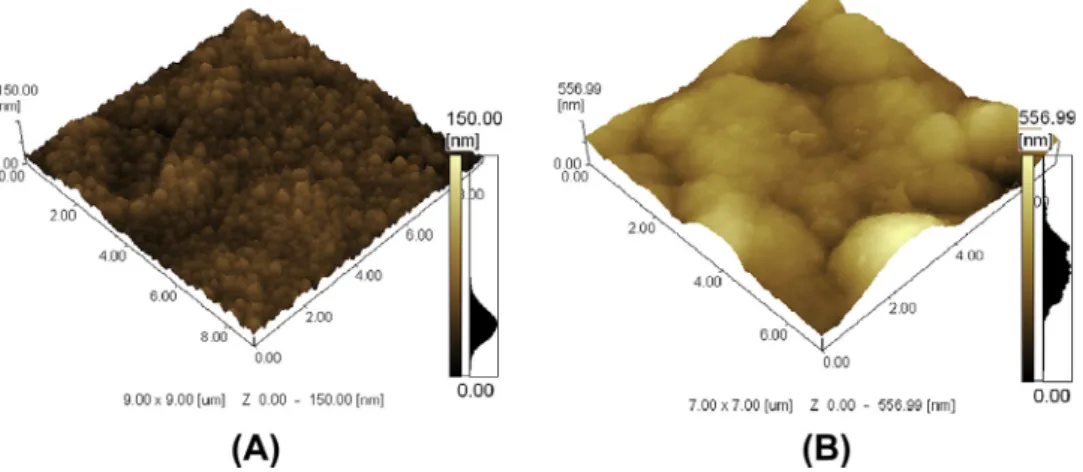
composed of small compact grains with the average size of 0.2
l
m. Films deposited on nitrided samples are composed of agglomerates of small grains with non-homogeneous size and higher Rms roughness (70.4 nm). Such aglomerates are larger than the small compact grains of films deposited on bare alloy. The observed increase (about six times) of surface roughness of the ni-tride alloy compared to the bare one is due to the sputtering in the nitriding process. The surface roughness affects the coating morphology, which can also be affected by the substrate chemical composition and by secondary electron emission from the sub-strates. The secondary electron emission from different substrates increases the plasma intensity differently, which may result in dif-ferent coating properties and morphology[22].As previously reported[23], the Raman spectra of our films pre-sents the characteristic D and G peaks, the D peak lying at approx-imately 1385 cm1and the G peak lying at around 1569 cm1. The term diamond-like carbon (DLC) has been employed to designate several kinds of carbon films. In order to be more specific, we adopt the nomenclature used by Casiraghi et al.[24]. Those authors char-acterize films with a hydrogen content lower than 20% as being graphite-like hydrogenated amorphous carbons (GLCH). The Raman spectra can be used to calculate the hydrogen content of the carbon films[23]: The hydrogen content of the films investi-gated in this study is about 16%.
3.2. Polarization curves
Fig. 2(A and B) shows polarization curves for GLCH films depos-ited on Ti–6Al–4V and nitrided Ti–6Al–4V, respectively. It can be seen that the GLCH films present similar behavior both deposited on bare and nitrided Ti–6Al–4V. Films present low current densi-ties indicating a superior corrosion protection conferred on the substrates.
The protective efficiency and coating porosity were determined from the polarization curves by empirical equations[25,26].
Pi¼100 1
icorr
iocorr
ð1Þ
F¼ RPðsubstrateÞ Rpðcoating—substrateÞ
10jDEcorrba j ð2Þ
wherePiis the protective efficiency,icorrandiocorrare the corrosion
current densities in the presence and absence of the coating.Fis the coating porosity,Rpthe polarization resistance of the substrate
or of the coated substrate,DEcorris the potential difference between
the free corrosion potentials of the coated alloy and the bare sub-strate andba, the anodic Tafel slope for the substrate.
values for films deposited on nitrided sample were about 95% and 0.02%.
It is well known that the titanium and its alloys present a pas-sive behavior in solutions that simulate the body environment due to the formation of a protective oxide layer[27]. With this alloy (Ti–6Al–4V) it is possible to observe low anodic current densities (0.8
l
A/cm2) in a wide range of potentials (from 0 to 1.6 VSCE). Comparing the bare alloy to nitrided alloy, it is possible to observe an increase in the corrosion potential associated with the forma-tion of a nitrided layer. Low anodic current densities (about 1.5
l
A/cm2) are observed until 1.1 VSCE. Afterwards an anodic peak is observed that may correspond to the oxidation of TiN to TiO2, according to Heide and Schultze [28]. Some breaks observed in the curve of GLCH deposited on nitrided Ti–6Al–4V at high overpo-tentials (above 1.1 VSCE) could be related to the oxidation of the substrate (TiN to TiO2).
3.3. EIS
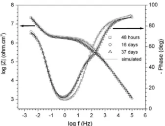
Fig. 3shows Bode plots of the EIS data obtained for GLCH depos-ited on bare Ti–6Al–4V and nitrided Ti–6Al–4V after 1 h of sample exposure to the simulated body environment. The similar behavior of both curves reveals that the electrochemical behavior of samples (GLCH covered alloy and GLCH covered nitrided alloy) is primarily determined by the GLCH coating. The phase angle in that figure
shows two mainly capacitive regions: one at high frequencies (about 104Hz) and another at low frequencies (below 104Hz). Those regions are of particular interest because they give informa-tion about GLCH film (high-frequency region) and informainforma-tion Fig. 1.Atomic force microscopy images for films deposited on (A) bare Ti–6Al–4V and (B) nitrided Ti–6Al–4V.
Fig. 2.Potentiodynamic polarization curves for GLCH films deposited on bare (A) and nitrided Ti–6Al–4V (B). The curves of the substrates are also shown. Experiments were performed in PBS solution at a sweep rate of 0.167 mV/s.
Fig. 3.Bode plots of GLCH films deposited on bare and nitrided Ti–6Al–4V immersed in PBS solution for a 1 h period. The solid lines show fit of the data by the equivalent circuits shown inFig. 3.
about the processes related to reactions at the electrolyte/substrate interface taking place in the pores of GLCH films (low-frequency region).
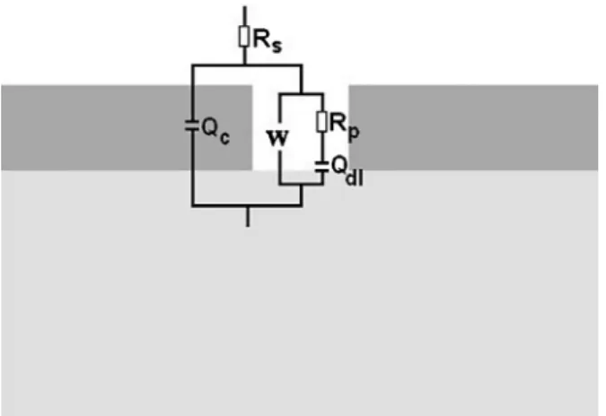
In order to understand the EIS measurements shown inFig. 3, we fit the impedance data using an equivalent electrical circuit, shown inFig. 4, that is representative of the physical processes tak-ing place in the system under investigation. The circuit is com-posed of an electrolyte solution resistance (Rs); a pore resistance
(Rp); a Warburg element (W) that represents the diffusion of ions
from the solution to the small pores and from the corroding sub-strate to the solution; two constant phase elements (CPE), repre-sent non-ideal capacitors, one regarding the GLCH film (Qc) and
another regarding the (Qdl) double-layer capacitance at the
electro-lyte/substrate interface.
In the frequency range studied the GLCH film resistance is much higher than the impedance of the other proposed circuit elements.
In that case we consider it infinite, or an open circuit, and represent the GLCH film by a constant phase element only (Qc). For the same
reason there is no resistance parallel to theQdlelement, the small
porous area combined with the good corrosion resistance of the Ti– 6Al–4V alloy makes the resistance to polarization at the electro-lyte/substrate interface also too high in comparison to the imped-ance of the remaining circuit elements. Thus, the proposed circuit is able to fit the data reproducing the predominance of capacitive behaviors at high (Qc) and low (Qdl) frequencies observed in Fig. 3. In Tables 1 and 2, which show circuit element values for films deposited on bare and nitrided alloy respectively, it is possi-ble to see that the values of the capacitance of GLCH films (Qc) are
in the range between 1.3 nF cm2and 2.0 nF cm2. Such capaci-tance values are similar to those found by other authors for hydro-genated amorphous carbon films[29,30], which corroborates our circuit model. The double-layer capacitance at the electrolyte/sub-Fig. 4.Schematic diagram of equivalent circuit for GLCH films deposited on bare Ti–
6Al–4V. The same equivalent circuit is also employed to simulate films deposited on nitrided Ti–6Al–4V for immersion times inferior to 16 days. For immersion times greater than 16 days the electrochemical behavior of films deposited on nitrided Ti– 6Al–4V is well described by the circuit shown inFig. 7.
Table 1
Fitting parameters of the impedance spectrum performed along the immersion times for GLCH deposited on bare Ti–6Al–4V.
1 h 48 h 7 days 16 days 23 days 30 days 37 days
RS(Xcm2) 20 20 20 19 19 20 19
QC(nF cm2) 1.8 2.0 2.0 2.0 2.0 2.1 2.1
nC 0.97 0.96 0.97 0.97 0.97 0.97 0.96
Y0(nS s1/2) 6.5 6.7 8.2 7.9 7.9 8.9 8.8
Qdl(lFvcm2) 1.8 1.9 1.9 1.9 1.8 1.9 1.9
ndl 0.89 0.9 0.91 0.90 0.90 0.91 0.89
Rp(kXcm2) 5190 4000 3510 3820 3930 3450 3380
Table 2
Fitting parameters of the impedance spectrum performed along the immersion times for GLCH deposited on nitrided Ti–6Al–4V.
1 h 48 h 7 days 16 days 23 days 30 days 37 days
RS(Xcm2) 20 20 20 18 18 18 18
QC(nFXcm2) 1.4 1.6 1.3 1.4 1.4 1.4 1.4
nC 1 0.99 1 1 1 1 1
Y0(nSXs1/2) 15 21 42 27 26 29 28
Qdl1(lFXcm2) 1.4 1.5 1.5 1.5 1.4 1.5 1.5
ndl1 0.90 0.90 0.92 0.90 0.90 0.90 0.89
Rp(kXcm2) 2570 2190 2070 2170 2160 1900 1990
Rck(kXcm2) – – – 910 690 910 710
Qdl2(nF cm2) – – – 3.7 5.0 5.1 5.5
ndl2 – – – 0.86 0.84 0.84 0.84
strate interface (Qdl) for bare and nitrided substrate are in the order
of 1–2
l
F cm2. The range of
l
F cm2is a well-known value for a metallic and nitrided surface immersed in an electrolytic solution with low resistance (as observed inTables 1 and 2)[31,32].
According to Tables 1 and 2, the pore resistance (Rp) of films
deposited on bare alloy is almost twice as large as the resistance of films deposited on nitrided alloy. Considering that the pore resistance is well described by:
R¼
q
LA ð3Þ
where
q
is the solution resistance,Lis the pore length andAis the pore area, it is reasonable to suppose that the pore area of films deposited on nitrided alloy is bigger than that of films deposited on bare alloy. In addition, the lower values of the Warburg coeffi-cient (which is inversely proportional to the magnitude of admit-tance (Y0) shown inTables 1 and 2) of films deposited on nitrided alloy in comparison to that of films deposited on bare alloy indi-cates that the pore area in films deposited on nitrited alloy is bigger than that of pores in films deposited on bare alloy. The Warburg coefficient (rw) is related to the area according to the followingexpression[33]:
r
w¼RT n2F2A ffiffiffi
2
p C 1
0pffiffiffiffiffiffiD0þ
1
CRpffiffiffiffiffiffiDR
ð4Þ
whereRis the gas constant;Tthe temperature;nthe number of electrons involved;Fthe Faraday constant;A the surface area of the electrode;C0the concentration of the oxidant ;D0the diffusion coefficient of the oxidant;CR the concentration of the reductant;
andDRis the diffusion coefficient of the reductant.
The indicative that the pores in films deposited on nitrided alloy are larger than those of films deposited on bare alloy is also ob-served in the lower protective efficiency and higher coating poros-ity obtained from polarization curves.
The admittance values (Y0) of both systems slowly increase over time due to the corrosion process that injects ions from the sub-strate into the electrolyte. Such a process also decreases pore resistance.
In spite of the presence of pores, the electrochemical behavior of films deposited on bare alloy does not change during the time tested as can be seen in Fig. 5, which shows the bode plot for 48 h and 37 days. This result indicates that films deposited on bare alloy present excellent corrosion resistance. On the other hand, films deposited on nitrided alloy change their electrochemical Fig. 6.Bode plots of GLCH films deposited on nitrided Ti–6Al–4V immersed in PBS
solution for 48 h, 16 days and 37 days. The solid lines show fit of the data by the equivalent circuits shown inFig. 3(48 h) andFig. 7.
Fig. 7.SEM image of a characteristic pore (A) on GLCH film deposited on nitrided alloy and a delaminated region (B) after 37 days of immersion in PBS solution. Fig. 8.Schematic diagram of equivalent circuit for GLCH films deposited on nitrided alloy after 16 days of immersion in PBS solution.
behavior after 16 days as can be seen inFig. 6, which shows the bode plot of GLCH deposited on nitrided samples for 48 h, 16 and 37 days. In order to understand the observed change in the electro-chemical behavior we have looked for morphological changes in the film by means of SEM images.Fig. 7A shows the SEM image of a characteristic pore of the film whileFig. 7B shows an area in which part of the film has been delaminated. At the borders of the defect it is possible to see a crack (circled area) and irregular-ities due to the cracking of the film. Such an image combined with the presence of pores suggests the following process: (i) water and ions penetrate through the pores reaching the metal/film interface; (ii) loss of adhesion between metal and film occurs due to corro-sion and penetration of fluid; (iii) the hard film cracks to release the tension due to fluid penetration at the interface. To further investigate such an hypothesis we include new circuit elements to represent a delaminated and cracked area around the pore as shown inFig. 8. The new circuit is composed of a solution resis-tance (Rs); a pore resistance (Rp); a crack resistance (Rck) that
rep-resents the electrolytic conduction at the cracked film; a Warburg element (W); three CPE, one for the GLCH film (Qc), another
repre-senting the (Qdl1) double-layer capacitance at substrate/electrolyte interface in the pore and another for the (Qdl2) double-layer capac-itance at the substrate/electrolyte interface in the detached and cracked regions of the film. As can be seen inFig. 6the new circuit fits very well the electrochemical behavior after 16 days, which supports the proposed process.
The double-layer capacitance (Qdl2) in detached and cracked regions of the film and mainly the crack resistance (Rck) are
ex-pected to be oscillating values as observed. This is because new cracks will be formed during the immersion days and the cracked film will be released, so the region is very unstable and changed its configuration throughout the days.
From the results discussed above, a question that naturally arises is why the delamination and cracking occur only in the films deposited on nitrided alloy during the time tested. It should be kept in mind that the nitrided alloy is rougher than the bare alloy, which should promote an anchor or interlocking effect. A possible explanation could be a weaker interaction be-tween the GLCH film and the nitrided substrate compared to the interaction between the GLCH film and the bare substrate. In fact, in a recent work[23]we used AFM force curve measure-ments to show that the interactions between a diamond covered tip and a nitrided surface are much less intense than those be-tween the same tip and a bare surface, which suggests that the interaction between hard carbon films and the nitrided alloy is weaker than the interaction between hard carbon films and the bare alloy.
GLCH films deposited on bare Ti–6Al–4V alloy are homoge-neous and composed by small, compact grains while those depos-ited on the nitrided alloy present a rougher morphology composed by not homogeneously sized grains.
Films deposited on both substrates present high corrosion resis-tance, however they contain pores that allow a diffusion process and corrosion of the substrate. After 16 days of immersion, films deposited on the nitrided alloy change their electrochemical behavior while films deposited on bare alloy remain unchanged. Our results point out that such a change in the electrochemical behavior is due to substrate/film interface degradation, film delam-ination and cracking. We associate the higher durability of films deposited on bare alloy compared with films deposited on nitrided alloy with the higher interaction between the film and the bare alloy, which is supported by previous AFM force curve measurements.
The GLCH films diminish the viability of osteoblast cells when compared with the uncovered alloy. The roughness of the tested surface showed no influence on this behavior.
Acknowledgments
The authors wish to acknowledge the financial support of the Brazilian government agencies CNPq, CAPES, FAPEMIG and INCT em Nanomateriais de Carbono (CNPq/MCTI).
References
[1]M. Niinomi, Mechanical properties of biomedical titanium alloys, Mater. Sci. Eng. A243 (1998) 231–236.
[2]S.L. Assis, S. Wolynec, I. Costa, Corrosion characterization of titanium alloys by electrochemical techniques, Electrochim. Acta 51 (2006) 1815– 1819.
[3]J.E.G. González, J.C. Mirza-Rosca, Study of the corrosion behavior of titanium and some of its alloys for biomedical and dental implant applications, J. Electroanal. Chem. 471 (1999) 109–115.
[4]M. Niinomi, Mechanical biocompatibilities of titanium alloys for biomedical applications, J. Mech. Behav. Biomed. Mater. 1 (2008) 30–42.
[5]T.M. Muraleedharan, E.I. Meletis, Surface modification of pure titanium and Ti– 6A1–4V by intensified plasma ion nitriding, Thin Solid Films 221 (1992) 104– 113.
[6]B.S. Yilbas, C. Karatas, Uslan, O. Keles, I.Y. Usta, M. Ahsan, CO2laser gas assisted
nitriding of Ti–6Al–4V alloy, Appl. Surf. Sci. 252 (2006) 8557–8564. [7]A. Zhecheva, W. Sha, S. Malinov, A. Long, Enhancing the microstructure and
properties of titanium alloys through nitriding and other surface engineering methods, Surf. Coat. Technol. 200 (2005) 2192–2207.
[8]I.M. Pohrelyuk, V.M. Fedirko, O.V. Tkachuk, R.V. Proskurnyak, Corrosion resistance of Ti–6Al–4V alloy with nitride coatings in Ringer’s solution, Corros. Sci. 66 (2013) 392–398.
[9]A.C. Fernandes, F. Vaz, E. Ariza, L.A. Rocha, A.R.L. Ribeiro, A.C. Vieira, J.P. Rivière, L. Pichon, Tribocorrosion behaviour of plasma nitrided and plasma nitrided + oxidised Ti6Al4V alloy, Surf. Coat. Technol. 200 (2006) 6218– 6224.
[10]T.M. Manhabosco, S.M. Tamborim, C.B. dos Santos, I.L. Müller, Tribological, electrochemical and tribo-electrochemical characterization of bare and
nitrided Ti6Al4V in simulated body fluid solution, Corros. Sci. 53 (2011) 1786– 1793.
[11]L. Ding, K. Nakasa, M. Kato, T. Inoue, Coating of TiB2 dispersed Ti50Ni50
superelastic alloy layer onto Ti–6Al–4V alloy by spark and resistance sintering, Surf. Coat. Technol. 204 (2010) 1738–1748.
[12]H.H. Huang, C.H. Hsu, S.J. Pan, J.L. He, C.C. Chen, T.L. Lee, Corrosion and cell adhesion behavior of TiN-coated and ion-nitrided titanium for dental applications, Appl. Surf. Sci. 244 (2005) 252–256.
[13]D. Turcio-Ortega, S.E. Rodil, S. Muhl, Corrosion behavior of amorphous carbon deposit in 0.89% NaCl by electrochemical impedance spectroscopy, Diamond Relat. Mater. 18 (2009) 1360–1368.
[14]E. Liu, H.W. Kwek, Electrochemical performance of diamond-like carbon thin films, Thin Solid Films 516 (2008) 5201–5205.
[15]T.M. Manhabosco, I.L. Muller, Electrodeposition of diamond-like carbon (DLC) films on Ti, Appl. Surf. Sci. 255 (2009) 4082–4086.
[16]P. Gupta, E.I. Meletis, Tribological behavior of plasma-enhanced CVD a-C: H films. Part II: Multinanolayers, Tribol. Int. 37 (2004) 1031–1038.
[17]S. Kobayashi, Y. Ohgoe, K. Ozeki, K. Sato, T. Sumiya, K.K. Hirakuri, H. Aoki, Diamond-like carbon coatings on orthodontic archwires, Diamond Relat. Mater. 14 (2005) 1094–1097.
[18]K. Gutensohn, C. Beythien, J. Bau, T. Fenner, P. Grewe, R. Koester, K. Padmanaban, P. Kuehnl, In vitro analyses of diamond-like carbon coated stents: reduction of metal ion release, platelet activation, and thrombogenicity, Thromb. Res. 99 (2000) 577–585.
[19]D. Bociaga, K. Mitura, Biomedical effect of tissue contact with metallic material used for body piercing modified by DLC coatings, Diamond Relat. Mater. 17 (2008) 1410–1415.
[20]J.C. Avelar-Batista, E. Spain, G.G. Fuentes, A. Sola, R. Rodriguez, J. Housden, Triode plasma nitriding and PVD coating: a successful pre-treatment combination to improve the wear resistance of DLC coatings on Ti6Al4V alloy, Surf. Coat. Technol. 201 (2006) 4335–4340.
[21]G.L. Peterson, Review of the folin phenol protein quantitation method of Lowry, Rosebrough, Farr and Randall, Anal. Biochem. 100 (1979) 201–220.
[22]K.S. Mogensen, N.B. Thomsen, S.S. Eskildsen, C. Mathiasen, J. Bøttiger, A parametric study of the microstructural, mechanical and tribological properties of PACVD TIN coatings, Surf. Coat. Technol. 99 (1998) 140–146. [23]T.M. Manhabosco, A.P.M. Barboza, R.J.C. Batista, B.R.A. Neves, I.L. Müller,
Corrosion, wear and wear–corrosion behavior of graphite-like a-C: H films deposited on bare and nitrided titanium alloy, Diamond Relat. Mater. 31 (2013) 58–64.
[24]C. Casiraghi, A.C. Ferrari, J. Robertson, Raman spectroscopy of hydrogenated amorphous carbons, Phys. Rev. B 72 (2005) 085401.
[25]K. Nozawa, K. Aramaki, One- and two-dimensional polymer films of modified alkanethiol monolayers for preventing iron from corrosion, Corros. Sci. 41 (1999) 57–73.
[26]B. Matthes, E. Broszeit, J. Aromaa, H. Ronkainen, S.-P. Hannula, A. Leyland, A. Matthews, Corrosion performance of some titanium-based hard coatings, Surf. Coat. Technol. 49 (1991) 489–495.
[27]A.K. Shukla, R. Balasubramaniam, S. Bhargava, Properties of passive film formed on CP titanium, Ti–6Al–4V and Ti–13.4Al–29Nb alloys in simulated human body conditions, Intermetallics 13 (2005) 631–637.
[28]N. Heide, J.W. Schultze, Corrosion stability of TiN prepared by ion implantation and PVD, Nucl. Instrum. Methods Phys. Res. B 80–81 (1993) 467–471. [29]A. Zeng, E. Liu, I.F. Annergren, S.N. Tan, S. Zhang, P. Hing, J. Gao, EIS capacitance
diagnosis of nanoporosity effect on the corrosion protection of DLC films, Diamond Relat. Mater. 11 (2002) 160–168.
[30] H.-G. Kima, S.-H. Ahn, J.-G. Kim, S.J. Park, K.-R. Lee, Corrosion performance of diamond-like carbon (DLC)-coated Ti alloy in the simulated body fluid environment, Diamond Relat. Mater. 14 (2005) 35–41.
[31]H.-G. Kim, S.-H. Ahn, J.-G. Kim, S.J. Park, K.-R. Lee, Corrosion performance of diamond-like carbon (DLC)-coated Ti alloy in the simulated body fluid environment, Diamond Relat. Mater. 14 (2005) 35–41.
[32]S. Rossi, L. Fedrizzi, T. Bacci, G. Pradelli, Corrosion behaviour of glow discharge nitrided titanium alloys, Corros. Sci. 45 (2003) 511–529.
[33]A.J. Bard, L.R. Faukner, Electrochemical Methods, John Wiley & Sons, New York, 1980.