Corrosion, wear and wear
–
corrosion behavior of graphite-like
a
-C:H
fi
lms deposited
on bare and nitrided titanium alloy
T.M. Manhabosco
a,⁎
, A.P.M. Barboza
b, R.J.C. Batista
a, B.R.A. Neves
b, I.L. Müller
caPhysics Department, Federal University of Ouro Preto, Campus Universitário Morro do Cruzeiro ICEB/DEFIS, 35400-000, Ouro Preto, Minas Gerais, Brazil bPhysics Department, Federal University of Minas Gerais, Av. Antonio Carlos 6627, 31270-901, Belo Horizonte, Minas Gerais, Brazil
cMetallurgy Department, Laboratory of Corrosion Research, Federal University of Rio Grande do Sul, Av. Bento Gonçalves 9500/75/232, 91501-970, Porto Alegre, Rio Grande do Sul, Brazil
a b s t r a c t
a r t i c l e
i n f o
Article history: Received 1 April 2012
Received in revised form 28 September 2012 Accepted 7 November 2012
Available online 15 November 2012
Keywords: Diamond-like carbon Tribology
Corrosion
Scanning probe techniques
This work presents a comparative wear, corrosion and wear–corrosion (the last one in a simulated physiological solution) study of graphite-likea-C:H (GLCH)films deposited on bare and nitrided Ti6Al4V alloy. Films, deposited by r.f. PACVD, presented low porosity and promoted high corrosion resistance. The friction coefficient of thefilms was very low with appreciable wear resistance at room conditions. However, due to the simultaneous action of both load and the corrosive environment in wear–corrosion tests a marked reduction in the coating lifetime was ob-served. Unexpectedly,films deposited on the nitrided alloy presented a lifetime at least ten times shorter than that offilms on bare alloy. We explain such a result in terms offilm/substrate interaction. The weak GLCH/nitrided alloy interaction facilitatesfluid penetration between thefilm and the substrate which leads to a fastfilm delamina-tion. Such an interpretation is supported by force curve measurements, which show that the interaction between GLCH and nitrided alloy is four times weaker than that between GLCH and bare alloy.
© 2012 Elsevier B.V. All rights reserved.
1. Introduction
Among metallic materials, titanium and its alloys have been most commonly chosen for use in implants. This choice is motivated by titani-um appropriate properties such as low density, high strength to weight ratio, good corrosion resistance, and above all, biocompatibility which is conferred by the thin and compact oxide (TiO2) spontaneously formed at its surface in the presence of oxygen[1–3]. However, in some applica-tions (in ankle and hip joints, for instance) superior mechanical wear and, mainly, wear–corrosion resistance are required, but not provided by those metals[4,5]. To extend the use of titanium to situations where superior resistance is required, researchers have been working to im-prove the surface properties of titanium and its alloys through mechan-ical, chemmechan-ical, thermo-chemical processes and/or coating deposition [6–10]. It is worth mentioning the work of Kumar et al.[8]who studied the fretting-corrosion behavior of untreated, anodized and thermally ox-idized pure titanium in Ringer's solution and observed an increase in the fretting-corrosion resistance after surface treatment. The thermally oxi-dized samples presented better fretting-corrosion resistance.
Regarding high performance coatings, diamond-like carbon (DLC) films have been pointed out as good candidates for coat implants such as hip and ankle joints besides heart valves and stents[11–13]. In fact, DLCfilms present exceptional properties such as wear resistance, high hardness, low friction coefficient, corrosion resistance, good bio- and
hemocompatibilities, high thermal conductivity, optical transparence to infrared and chemical inertness[11–16], which support their use in a wide range of applications. DLC is a relatively new class of amorphous carbon materials with a significant content of C\C sp3bonds, which
confers them some of the properties previously cited. Moreover, DLC films may contain other elements such as hydrogen, nitrogen and sili-con that can alter their structure and properties[16–18]. The hydroge-nated amorphous carbons are classified into four types: polymer-like a-C:H (PLCH),films with 40–60 at.% of H content; diamond-like a-C:H (DLCH),films with 20–40 at.% of H content; hydrogenated tetrahedral amorphous carbon films (ta-C:H); and graphite-like a-C:H (GLCH) with low H content (less than 20 at.%).
Besides the appropriate properties of thefilms, their adhesion to the substrate is mandatory for a biomaterial to be implanted inside a living body. One problem regarding DLCfilms on titanium and its alloys is the failure and detachment of the coating. The failure of the coating may be due to the plastic deformation of the substrate, the cracking of the coating and/or the failure of the interface since there is a mismatch in the mechanical and chemical properties of those two materials (i.e., the hard and brittle coating is not capable of withstanding plastic deformation as well as the soft substrate which results in cracks and de-lamination of thefilm). Interlayers and surface treatments have been used to overcome this problem and improve the load-bearing capacity as they provide a gradual change in the hardness and better tension dis-tribution from the coating to the substrate[19–21]. Such treatments and interlayers indeed improve thefilms resistance to wear or corrosion in situations where load and corrosive environment are not acting together. However, in some applications, like ankle and hip joints, load and a
⁎ Corresponding author at: Campus Universitário Morro do Cruzeiro ICEB/DEFIS, Ouro Preto, Minas Gerais, 35400-000, Brazil. Tel.: +55 31 35591675; fax: +55 31 35591667.
E-mail address:[email protected](T.M. Manhabosco).
0925-9635/$–see front matter © 2012 Elsevier B.V. All rights reserved. http://dx.doi.org/10.1016/j.diamond.2012.11.005
Contents lists available atSciVerse ScienceDirect
Diamond & Related Materials
corrosive environment must be taking into account. Unfortunately, in wear–corrosion solicitations a catastrophic failure of the DLCfilms has been recently observed[22]showing that DLC coatings cannot safely be used yet in situations in which load and corrosive environment are acting together. To extend the use of DLC coatings to such situations, it is mandatory to understand the features related to the catastrophic fail-ure mechanism.
In the present work we investigate the changes in the mechanical and electrochemical behavior of bare and nitrided Ti6Al4V alloy sur-faces due to the GLCH coating deposited by r.f. PACVD. We observe a catastrophic failure of GLCHfilms on both substrates in wear–corrosion tests. In spite of the hardness gradient and better physical anchorage provided by the roughness of the nitrided substrate, the coating depos-ited on it fails much earlier than that deposdepos-ited on bare alloy.
2. Experimental details
2.1. Materials, surface treatment and coating deposition
Ti6Al4V alloy (grade 5) disc samples with 38 mm in diameter and mean thickness of 17 mm were obtained from a bar. Samples were ground with SiC emery paper to 800 grit and polished with colloidal sil-ica. After polishing, the samples were ultrasonically cleaned in acetone for 10 min followed by rinsing in methanol and deionized water. After preparation, the surface roughness (Ra) of the samples was about 25 nm. Some samples were nitrided in a gas mixture of 10% Ar, 50% H2and 40% N2at 300 Pa for 10 h. The temperature of the process (1073 K) was chosen below the transition temperature of the alloy (1228 K). The nitrided layer microstructure was analyzed by X-ray diffraction (X Philips—X'Pert MRD) with Cu Kαradiation (λ= 1.5406 Å).
The coatings were commercially deposited on the Ti6Al4V polished samples and on the nitrided samples (not polished after nitriding pro-cess) using r.f. (13.56 MHz) PACVD technique. The samples were placed at the top of the chamber to avoid dust particles. Prior to deposition the reaction chamber was evacuated to a base pressure of ca. 1.5 Pa and samples were cleaned by sputtering with argon (Ar) for 20 min. The de-position was performed at 1.5 Pa with acetylene (C2H2)flowing at a rate of 50 sccm for 2 h. The negative self-bias voltage of the r.f. powered electrodes was 1000 V. Thirty bare and thirty nitrided Ti6Al4V samples were single side coated with 4μm thickfilms.
2.2. Surface and coating characterizations
The nitrided samples were characterized by scanning electron mi-croscopy (SEM) and X-ray diffraction as previously published[23].
The surface morphology of the coatings deposited on bare and nitrid-ed samples was acquirnitrid-ed by atomic force microscopy (AFM—Shimadzu model SPM-9500J3) in the contact mode and the surface roughness was estimated from AFM images. The coatings were analyzed by Raman spec-troscopy performed with a NTEGRA Spectra Nanofinder (NT-MDT) oper-ating at 514.5 nm excitation. The cooper-ating hardness was acquired from nanoindentation tests using a CETR nanohardness tester. The maximum load in each indentation was 100 mN with no penetration depth higher than 20% of thefilm thickness. A Vickers indenter and the Oliver and Pharr[24]method were used to determine hardness.
A Nanoscope IV MultiMode SPM, from Veeco Instruments, was employed for force spectroscopy analysis of bare and nitride samples. SPM measurements were carried out in air, or under dry nitrogen atmo-spheres, with the help of homemade environmental control chambers. Heating experiments were carried out with a commercial hot stage AFM setup (Veeco Instruments MultiMode SPM with High Temperature Heater accessory). The used silicon cantilevers were covered with a thin doped-diamondfilm, from NT-MDT, with k~2.5–10 N/m, R~30–50 nm andω0~115 to 190 kHz. More accurate estimations of k and R were car-ried out by the use of the Sader's method[25]and by imaging reference samples, respectively. During the heating process, most of the water
layer is removed. This layer is responsible for the capillary forces when the tip comes into contact with the sample surface and a water meniscus is formed. Therefore, using the hot stage, the adhesion force between the diamond tip and the sample surface can be measured with reduced infl u-ence of the water layer.
2.3. Corrosion tests
The corrosion behavior of the samples was evaluated by means of potentiodynamic polarization curves in a simulated bodyfluid environ-ment (phosphate buffered saline solution (PBS)) at a scan rate of 0.167 mV/s using an EG&G 273A potentiostat. The PBS solution used was composed of 8 g/l NaCl; 0.2 g/l KCl; 0.594 g/l Na2HPO4and 0.2 g/l KH2PO4, pH=7.1. The tests were performed in a three-electrode cell with the temperature controlled at 37 °C (±1 °C) by a thermostatic bath. A saturated calomel electrode (SCE) was used as reference elec-trode and platinum wire as counter elecelec-trode. The exposed area of the samples (3.14 cm2) was determined by a Te
flon o-ring. Before the beginning of the corrosion tests the system was maintained 1 h in the solution in order to stabilize the open circuit potential (OCP).
The protective efficiency of the coatings was determined from the polarization curves by the empirical equation[26]:
Pi¼100 1−icorr=i
corr
ð1Þ
where icorrand i°corrare the corrosion current densities in the presence and absence of the coating.
The total coating porosity was estimated from electrochemical measurements using the following equation[27]:
P¼ Rpm substrateð Þ=Rp coatingð −substrateÞ
x10−ΔEcorr=βaj
j ð2Þ
where Rpmthe polarization resistance of the substrate, Rpthe measured polarization,ΔEcorris the potential difference between the free corro-sion potentials of the coated alloy and the bare substrate andβa, the an-odic Tafel slope for the substrate.
2.4. Wear tests
The tribological behavior of thefilms at room conditions (relative hu-midity about 25% and 20 °C) was evaluated by wear tests carried out in a reciprocating pin-on-plate tribometer controlled by a computer. The tests were performed by applying a normal load of 16 N, sliding velocity of 32 mm/s and 8 mm wear track length. Tests were performed for 2 h or until coating failure. The counter body used was an alumina ball (∅ 5 mm, Saphirwerk). At the end of each wear test, the wear track was analyzed by optical and SEM microcopy. The wear track profile was recorded by a profilometer (MicroGlider, Fries Research & Technology) and the wear volume was integrated from the wear track profile.
2.5. Wear–corrosion tests
At the end of each wear–corrosion test, the wear track profile was recorded by a profilometer and the wear track volume was calculated by integrating the wear track profile. The wear track was also ana-lyzed by optical and SEM microcopy.
3. Results and discussion
3.1. Coatings
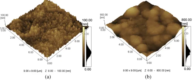
Atomic force microscopy images of the coatings deposited on bare and nitrided alloy are shown inFig. 1. Films deposited on bare alloy are composed of small compact grains homogeneously distributed on the surface with a mean roughness (Ra) of about 7.9 nm calculated from 9× 9μm images. Films deposited on nitrided samples show
large grains composed of agglomerated small grains with a roughness (Ra) of about 61.2 nm obtained from 9 ×9μm images. The difference in the coating morphology can be ascribed to the substrate chemical composition and morphology, since the alloy was exposed to both the sputtering process, for oxide removal, and nitriding process[28]. Also, secondary electron emission from the two substrates (bare and nitride samples) increases differently the plasma intensity that results in different coating morphology and properties[29]. It should be pointed out that the nitriding process was responsible for the for-mation of the Ti2N phase (tetragonal) and the TiN phase (cubic face centered) and also for increasing the surface roughness of Ti6Al4V samples from (Ra) of 25 nm to about (Ra) 150 nm[23].
The coatings deposited on both bare and nitrided samples were characterized by Raman spectroscopy as shown inFig. 2. The spectral shape wasfitted with Gaussians that reveals the common features of DLCfilms, the so-called D and G peaks. The D peak lies at approxi-mately 1385 cm−1 while the G peak lies at around 1569 cm−1. Ferrari et al.[30]have shown that Raman spectroscopy is a powerful technique to characterize DLCfilms. According toFig. 3of their man-uscript, the position of G peak of ourfilms corresponds to an sp3 con-tent of about 33%. The amount of H in thefilm can be estimated from the photoluminescence background slope as shown by Casiraghi et al. [18]. Using the equation below (Eq. (1) of Ref.[18]), we obtained a hydrogen content of about 16%.
H at½ : % ¼21:7þ16:6log mf =I Gð Þ½μmg ð3Þ
where m is the slope of the spectra measured between 1050 and 1800 cm−1and I(G) is the height of the G peak.
Indeed, the spectrum shown inFig. 4 is very similar to those of Casiraghi et al.[18]for the same hydrogen content. The amount of
hydrogen combined with the sp3content allows us to determine the sp2content from the ternary diagram presented by Casiraghi et al.[31]. Hydrogenated amorphous carbon with 33% of sp3bonds and a hydrogen content of 16% presents a sp2content of 51% resulting in a sp3/sp2ratio of 0.65.
According to Casiraghi et al.[31],films with low H content, lower than 20%, present a high sp2content and clustering with a band gap lower than 1 eV. Casiraghi et al.[18,31]used the term graphite-like hydrogenated amorphous carbons (GLCH) to denominate this type of DLCfilms with low H content. The ID/IGratio, a qualitative indicator of the nature of the bond and degree of graphitization, was calculated as being 0.60
The nanohardness measurements of thefilms result in values of 16.87±0.54 GPa. The literature presents a wide range of values for DLCfilm nanohardness that is mainly related to the amount of hydrogen incorporated into thefilm, to the ID/IGratio and sp3content[32–34].
3.2. Corrosion results
Fig. 3presents the potentiodynamic polarization curves in PBS solution for the bare alloy, the nitrided alloy and the GLCH coatings deposited on both bare and nitrided alloy. The bare alloy presents a passive behavior in the simulated bodyfluid environment with anod-ic current densities of about 8× 10⁻⁷A/cm2in a wide range of anodic potentials. The electrochemical behavior after nitriding indicates that
Fig. 1.AFM images of DLCfilms deposited on bare (a) and nitrided (b) alloy.
the alloy becomes nobler and with lower anodic current densities until 0.75 VSCE, indicating an increase in the corrosion resistance. At higher potentials an anodic peak is found that, according to the Pourbaix diagram proposed by Heide and Schultze[35], may corre-spond to the oxidation of TiN to TiO2as previously published[23].
GLCHfilms deposited on both bare and nitrided samples present similar behavior with lower current densities indicating superior cor-rosion protection. The protective efficiency and porosity of thefilms deposited onto bare alloy were calculated as being about 97% and 0.01, and for GLCHfilms deposited on nitride samples as being around 95% and 0.02. Statistically there is no significant difference in the values and comparing the polarization curves in the PBS solution, for GLCH deposited on both substrates, they present no important dif-ferences. Only at higher overpotentials the GLCH deposited on nitrid-ed alloy presents some breaks that could be associatnitrid-ed with the oxidation of TiN to TiO2.
3.3. Wear results
From the wear tests performed at room conditions a friction coefficient of about 0.43 and 0.38 was found for nitrided and bare alloy, respectively. Samples coated with GLCH presented an ex-pressive reduction in the friction coefficient; values of about 0.04 were observed, in agreement with data reported in the literature [37–41]. As expected for a hard material with a low friction coefficient the wear track volume was very low, 6.5×10⁻¹³m3for
films de-posited on nitrided alloy and 4.0× 10⁻¹³m3for
films on bare alloy. Such values correspond to wear rates of 1.76× 10⁻⁷mm3/Nm and 1.8× 10⁻⁷mm3/Nm, respectively. Such a difference is probably relat-ed to the roughness of GLCH coatings depositrelat-ed on nitridrelat-ed alloy since at the beginning of the wear test the load concentrates at the top of the asperities (the shear stress at the tops of the asperities is higher due to their small area). Bare samples tested with the same pa-rameters showed a wear track volume some 3700 times larger, which indicates that GLCH is an excellent coating to improve the wear resis-tance of titanium alloy in room conditions.
Several tests were carried out until the coating failed. GLCHfilms deposited on bare alloy resisted from 4.1 up to 4.6 km wear distance, whilefilms deposited on nitrided alloy resisted from 4.2 up to 5.4 km until failure. This slight increase in the mean lifetime could be related to the hardness gradient of GLCHfilms deposited on nitrided samples (which present a diffusion zone along 30μm from the top surface) that avoid the eggs shell effect and/or to the better physical anchor-age provided by the roughness (seeSection 3.1).
3.4. Wear- corrosion results
The wear–corrosion behavior of thefilms at OCP conditions was monitored for 2 h as shown inFig. 4. The vertical line indicates the beginning of wear.
It can be observed after beginning of wear that potential of GLCH coated bare alloy decreases slowly until the end of the test. Such a de-creasing behavior can be related to the combined action of the normal wear force and corrosive environment through film pores and/or microcracks formed during the test.
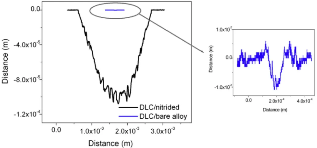
GLCHfilms deposited on bare alloy suffer low wear after the two hour test, as can be seen inFig. 5. The total wear volume calculated in this sample was about 5 ×10⁻¹⁴m3, which corresponds to a wear rate of 1.37 ×10⁻⁸mm3/Nm. After the test the alumina ball was analyzed in SEM and optical microscope and no transferred layer or damage could be observed.
Films deposited on nitrided alloy, on the other hand, suffered a catastrophic failure 16 min after wear began, that represents a wear distance of only 0.03 km in wear–corrosion tests. After failure the po-tential abruptly changes to values representative of bare alloy indicat-ing the complete removal of both GLCH film and nitrided layer. According to the GLCH/nitrided wear profile (Fig. 5) a deep wear track of 1× 10⁻⁴m, a value higher than the thickness of the GLCH coating plus the compound layer plus diffusion zone, confirms the at-tainment of the bare alloy. The total wear volume was around 4.7× 10⁻⁴m3 (wear rate of 127.5 mm3/Nm), 1010 times higher than in the case of GLCH deposited on bare alloy.Fig. 6shows the severe damages on the sample and on the counter-body after wear–
corrosion test. It can be observed that the counter-body was severely damaged and presents a transferred layer. The morphology of the wear track clearly indicates the occurrence offilm delamination on borders, asperity deformation and ploughing.
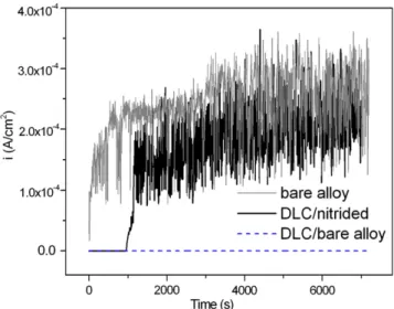
Fig. 7presents the ianodversus time behavior obtained from wear– corrosion tests at an anodic potential of 0.4 VSCEand also the corro-sion behavior of the bare alloy at 0.4 VSCEwithout wear for compari-son. The GLCH coatings deposited on nitrided alloy also fail, in agreement with results obtained in wear–corrosion tests at OCP con-ditions. The lifetime of thefilms was between 0.02 and 0.03 km, and after coating failure the corrosion current density fast reaches that of bare alloy, around 2× 10⁻⁴A/cm2. The current density oscillations on bare alloy are due to rapid repassivation after mechanical wear, i.e. depassivation/repassivation events[23,36].
In a previous work[23]it was shown that the nitriding process in-creases the wear–corrosion resistance of Ti6Al4V alloy; thus one Fig. 3.Potentiodynamic polarization curves in PBS solution for bare alloy, nitrided alloy
and DLCfilm deposited on both bare and nitrided alloy. Sweep rate: 0.167 mV/s.
could expect that the nitrided layer should provide additional wear–
corrosion protection after the GLCH failure. However, the injection of hard and chemically stable GLCH particles, which act as a hard third body, combined with the high normal load cause severe damage to the material (including the nitrided layer) and to the counter-body. The worn material and counter-body also inject new particles into the contact region and other wear mechanisms such as fatigue and adhe-sive wear take place simultaneously besides corrosion and abraadhe-sive wear.
GLCHfilms deposited on bare alloy develop an anodic current densi-ty about 1.6×10⁻⁸A/cm2during 2 h of test, indicating superior wear
–
corrosion protection under the tested conditions. However,films de-posited onto bare alloy also fail and the distance to failure varied from 0.37 up to 2 km. Since all tested GLCH coatings present pores that allow the diffusion of ions and water penetration into them, the failure
could be associated to the loss of adhesion between the GLCH/metal and to GLCH/metal interface degradation associated to the action of both load and corrosive environment. Thefilm deposited on bare alloy showed a wide range of rubbing distances until failure that can be asso-ciated to the probability of occurrence of defects on the wear track or near it (close enough to suffer the adverse effect of both load and corro-sive environment). Films free of pores or with no through-film defects, that do not allow water and ions to reach thefilm/substrate interface, can be good candidates to increase the tribocorrosion resistance. Park et al.[42]tested DLC coatings deposited on Ti6Al4V using a ball-on-disk type wear rig, some in aqueous environment (deionized water) and others in ambient air of relative humidity about 25%. Films tested in aqueous environment presented delamination, which can be closely related to the penetration of water via through-film defects that cause degradation of the interfacial strength. Authors suggest that the lifetime Fig. 5.Wear track profile of DLC deposited on bare and nitrided samples (a) after 2 h of wear–corrosion test at OCP and wear at a normal load of 16 N and sliding velocity of 32 mm/s. The wear track on bare alloy is amplified for a better view of its profile.
of the coating can be increased by eliminating the through-film defects and prove that multi-step coating was a good alternative to reduce through-film defects.
In wear tests,films deposited on nitrided alloy tested at room con-ditions presented a longer lifetime than films deposited on bare Ti6Al4V. However, when wear–corrosion tests were performed the lifetime of coatings deposited on nitrided alloy was significantly re-duced compared to that deposited onto bare alloy, despite the hard-ness gradient and higher roughhard-ness. The porosity index in GLCH deposited on nitrided samples is a little higher than that of GLCH on bare samples, therefore, the observed reduction in lifetime cannot be associated with thefilm porosity. One possibility for this occur-rence could be poor chemical affinity between the coating and the ni-trided layer in comparison to that of GLCH and bare substrate. Water and aggressive ions penetrate into the pores and, due to the poor GLCH/nitride layer chemical affinity, they can more easily penetrate between the GLCH/nitride layer interface leading to its faster degra-dation. Such an interpretation is supported by AFM force curve mea-surements acquired with an atomic force microscope between a diamond tip and the substrates (bare Ti6Al4V and nitrided alloy), as presented inFig. 8.
It is possible to observe higher adhesion forces between the dia-mond tip and bare alloy with a pull-off force about 24.2 nN, while the pull-off force for the nitrided alloy was about 6.1 nN. In most cases the adhesion force, defined by intermolecular interactions, is a combi-nation of the electrostatic force, the van der Waals force, the meniscus or capillary force and forces due to chemical bonds[43]. As the menis-cus or capillary forces were eliminated by thermal treatment and the pull-off forces are too small to represent chemical bonds, the measured forces are a combination of the remaining forces. The lower adhesion forces observed for the nitrided alloy could be the main cause of prema-ture failure in tribocorrosion tests of the GLCH deposited on nitrided alloy.
4. Conclusions
Diamond-like carbonfilms with high hardness and low friction co-efficient were produced by r.f. PACVD on bare and nitrided Ti6Al4V. Films proven to be effective to improve the wear resistance of bare and nitrided alloy with lifetime extend up to 5.4 km of wear distance in the tested room conditions. Besides, the protective efficiency and porosity of thefilms indicate a good quality of thefilms that conferred good corrosion protection on the bare and nitrided alloy.
A catastrophic failure was observed whenfilms were subjected to wear–corrosion conditions. GLCH films deposited on bare alloy presented a reduced lifetime from 0.37 to 2 km while GLCHfilm de-posited on the nitrided sample failed in thefirst 16 min of the test, which correspond to 0.02–0.03 km lifetime. The catastrophic failure of thefilms deposited onto both substrates could be related to the water and ions penetration through the pores that could lead to the loss of adhesion between GLCH and substrate and/or to the degrada-tion of GLCH/substrate interface due to the acdegrada-tion of both load and corrosive environment.
The premature failure offilms deposited on the nitrided alloy could be associated to the weak interaction between GLCH and the nitrided alloy in comparison to that between GLCH and the bare alloy, which was supported by AFM curve forces.
Acknowledgments
The authors wish to acknowledge thefinancial support of the Brazilian government agencies CNPq, CAPES and FAPEMIG. Authors are grateful to the Fraunhofer Institute (Stuttgart, Germany) for allowing the wear tests and Raman measurements.
References
[1] X. Liu, P.K. Chu, C. Ding, Mater. Sci. Eng. R 47 (2004) 49–121. [2] M. Niinomi, J. Mech. Behav. Biomed. Mater. 1 (2008) 30–42.
[3] J.L. Katz, in: B.D. Ratner, A.S. Hoffman, F.J. Schoen (Eds.), Biomaterials Science: An Introduction to Materials in Medicine, Academic, Orlando, 1996, pp. 335–346. [4] F. Contu, B. Elsener, H. Böhni, Electrochim. Acta 50 (2004) 33–41.
[5] T.M. Manhabosco, I.L. Muller, Quim. Nova 32 (2009) 2263–2267.
[6] R. Venugopalan, M.A. George, J.J. Weimer, L.C. Lucas, Biomaterials 20 (1999) 1709–1716.
[7] S. Kumar, T.S.N.S. Narayanan, S.G.S. Raman, S.K. Seshadri, Corros. Sci. 52 (2010) 711–721.
[8] S. Kumar, T.S.N.S. Narayanan, S.G.S. Raman, S.K. Seshadri, Mater. Sci. Eng. C 30 (2010) 921–927.
[9] A.C. Fernandes, F. Vaz, E. Ariza, L.A. Rocha, A.R.L. Ribeiro, A.C. Vieira, J.P. Rivière, L. Pichon, Surf. Coat. Technol. 200 (2006) 6218–6224.
[10] M.K. Lei, Z.H. Dong, Z. Zhang, Y.F. Hu, X.P. Zhu, Surf. Coat. Technol. 201 (2007) 5613–5616.
[11] R. Hauert, Diam. Relat. Mater. 12 (2003) 583–589.
[12] P.D. Maguire, J.A. McLaughlin, T.I.T. Okpalugo, P. Lemoine, P. Papakonstantinou, E.T. McAdams, M. Needham, A.A. Ogwu, M. Ball, G.A. Abbas, Diam. Relat. Mater. 14 (2005) 1277–1288.
[13] G. Thorwarth, C.V. Falub, U. Müller, B. Weisse, C. Voisard, M. Tobler, R. Hauert, Acta Biomater. 6 (2010) 2335–2341.
[14] Y. Wang, L. Wang, S.C. Wang, G. Zhang, R.J.K. Wood, Q. Xue, Tribol. Lett. 40 (2010) 301–310.
[15] C.L. Chen, L.G. Liu, Z.F. Ni, Adv. Mater. Res. 199–200 (2011) 683–688. [16] R. Hauert, Tribol. Int. 37 (2004) 991–1003.
Fig. 7.Evolution of the anodic current density with time in wear–corrosion tests at 0.4 VSCE, wear at a normal force of 16 N and sliding velocity of 32 mm/s.
[17] A.P.M. Barboza, S.S. Carara, R.J.C. Batista, H. Chacham, B.R.A. Neves, Small 8 (2012) 220–224.
[18] C. Casiraghi, F. Piazza, A.C. Ferrari, D. Grambole, J. Robertson, Diam. Relat. Mater. 14 (2005) 1098–1102.
[19] L. Hongxi, J. Yehua, Z. Rong, T. Baoyin, Vacuum 86 (2012) 848–853.
[20] S.B.A. Suilik, M. Ohshima, T. Tetsui, K. Hasezaki, Vacuum 82 (2008) 1325–1331. [21] J.C. Avelar-Batista, E. Spain, G.G. Fuentes, A. Sola, R. Rodriguez, J. Housden, Surf.
Coat. Technol. 201 (2006) 4335–4340.
[22] T.M. Manhabosco, I.L. Müller, Tribol. Lett. 33 (2009) 193–197.
[23] T.M. Manhabosco, S.M. Tamborim, C.B. dos Santos, I.L. Müller, Corros. Sci. 53 (2011) 1786–1793.
[24] W.C. Oliver, G.M. Pharr, J. Mater. Res. 7 (1992) 1564–1583.
[25] J.E. Sader, J.W.M. Chon, P. Mulvaney, Rev. Sci. Instrum. 70 (1999) 3967–3969. [26] K. Nozawa, K. Aramaki, Corros. Sci. 41 (1999) 57–73.
[27] B. Matthes, E. Broszeit, J. Aromaa, H. Ronkainen, S.-P. Hannula, A. Leyland, A. Matthews, Surf. Coat. Technol. 49 (1991) 489–495.
[28] W. Xu, L.J. Huang, Y.Z. Shih, T. Kim, Y. Hung, G. Li, Thin Solid Films 355–356 (1999) 353–356.
[29] K.S. Mogensen, N.B. Thomsen, S.S. Eskildsen, C. Mathiasen, J. BØtiger, Surf. Coat.Technol. 99 (1998) 140–146.
[30] A.C. Ferrari, B. Kleinsorge, G. Adamopoulos, J. Robertson, W.I. Milne, V. Stolojan, L.M. Brown, A. LiBassi, B.K. Tanner, J. Non-Cryst. Solids 266–269 (2000) 765–768. [31] C. Casiraghi, A.C. Ferrari, J. Robertson, Phys. Rev. B 72 (2005) 085401–085414. [32] E. Staryga, G.W. Bak, Diam. Relat. Mater. 14 (2005) 23–34.
[33] G. Messina, A. Paoletti, S. Santangelo, A. Tebano, A. Tucciarone, Microsyst. Technol. 6 (1999) 30–36.
[34] S. Reuter, B. Weßkamp, R. Büscher, B. Barden, F. Löer, V. Buck, Wear 261 (2006) 419–425.
[35] N. Heide, J.W. Schultze, Nucl. Inst. Methods Phys. Res. B 80–81 (1993) 467–471. [36] J. Komotori, N. Hisamori, Y. Ohmori, Wear 263 (2007) 412–418.
[37] Y. Liu, A. Erdemir, E.I. Meletis, Surf. Coat. Technol. 82 (1996) 48–56.
[38] A. Erdemir, O.L. Eryilmaz, G. Fenske, J. Vac. Sci. Technol. A 18 (2000) 1987–1992. [39] P. Gupta, E. Meletis, Tribol. Int. 37 (2004) 1031–1038.
[40] C.B. Santos, L. Haubold, H. Holeczek, M. Becker, M. Metzner, Tribol. Lett. 37 (2010) 251–259.
[41] M. Azzi, M. Paquette, J.A. Szpunar, J.E. Klemberg-Sapieha, L. Martinu, Wear 267 (2009) 860–866.