Polímeros: Ciência e Tecnologia, vol. 16, nº 4, p. 319-322, 2006 319
!
2
4
)
'
/
4
#
.
)
#
/
#
)
%
.
4
Ù
&
)
#
/
Inscription of Local Surface Relief Gratings with a Scanning
Near-field Optical Microscope on an Azo-polymer Film
Ivan H. Bechtold Departamento de Física, UFSC
Burkhard Stiller, Ludwig Brehmer Institute of Physics, University of Potsdam, Germany
Elisabeth A. de Oliveira Instituto de Física, USP-SP
Abstract: A Scanning Near-field Optical Microscope (SNOM) was used to inscribe locally limited Surface Relief Gratings (SRGs) on pDR1M, which is an azo-polymer film. The influence of parameters such as the line scanning time and the line spacing on the amplitude and the period of the gratings is discussed. SRGs have been used to orient Liquid Crystals (LCs), where the LC alignment takes place due to the elastic distortions of the nematic medium close to the surface. In addition, the photoalignment of the azo-chromophores was also used to induce LC alignment. In this work we investigate the use of local SGRs together with the photoalignment to get a local control of the LC alignment properties. The advantage of this method is that it is reversible and the gratings can easily be erased.
Keywords: Azo-polymer, surface relief gratings, SNOM, liquid crystal.
Introduction
In the last years many researchers have studied azoben-zene-containing films due to the possibility of technological applications[1]. For these purposes, the presence of the azo-benzene groups is essential and the so called trans-cis-trans
photoisomerization process make these materials good candidates for optical storage[2,3], optical switches[4] holo-grams[5], etc. A relatively new phenomenon is the optically induced mass transport resulting in SRGs[6-9]. The SRGs are usually formed by the incidence of a periodic optical pattern on the film, which, in most cases is produced by light in-terference patterns with appropriate wavelength (according to the absorption spectrum of the material) and polarized light[10]. The mechanisms responsible for the SRGs forma-tion have been intensively investigated, but the physical processes are still not completely understood. Most of the authors consider that azo-polymers with high glass transi-tion temperatures under low intensity writing conditransi-tions, the surface modulation basically arises from light-driven mass transport, with negligible thermal effects; in other si-tuations, thermal ablation and photodegradation processes can also be present[11].
The azopolymers have also been applied as aligning LC substrates, where they showed to be an alternative process to the usual rubbing of polymeric surfaces. The photoalign-ment process consists of the polymer surface irradiation with linear polarized light, resulting in the alignment of the azo groups perpendicular to the light polarization direction. The
LC molecules tend to align parallel to the azo-dye groups and the anchoring energy depends on the concentration of the chromophores in the film and on the irradiation time[12]. The use of SRGs for LCs alignment has been studied[13,14], where the LC molecules tend to align with the longest axis along the direction of the grating channels, due to the mini-mization of the elastic distortions close to the surface. The azimuthal anchoring energy (Wφ) presents good agreement with the phenomenological description of Berreman[15]. This description considers the anchoring energy in the pla-ne of the surface, which depends only on the morphological surface parameters and on the elastic energy of the medium:
Wφ = 2π3Ka2/p3, where a and p are the amplitude and the
period of the grating, respectively, and K is the mean value of the splay and bend LC elastic constants.
Recently, a SNOM was used to create surface structures and to erase a previous inscribed SRG, where non periodic structures were inscribed on pDR1M, which is not possible with usual interferometric techniques[16,17]. The SNOM ope-rates with a laser beam focused on an aperture on the tip, which is responsible for the photochemical effects in the near-field scale. The use of SNOM allows the controlling of the inscription process of a SRG in the micrometer and submicrometer range, by choosing freely some parameters as the amplitude, the periodicity, location, dimension and the shape of the grating.
In this work, we used a SNOM tip like a pen to inscribe locally SRGs on an azobenzene-containing polymer film (pDR1M), where we discuss parameters as the inscription
Bechtold, I. H. et al. - Inscription of local surface relief gratings
320 Polímeros: Ciência e Tecnologia, vol. 16, nº 4, p. 319-322, 2006
time and line separation to control the amplitude and the pe-riod of the pepe-riodic gratings. The aim of this work is the ap-plication of these surfaces to orient LCs, given the importan-ce of having a local control of the LC alignment. In addition, the fotoalignment properties and azimuthal anchoring energy are also investigated for this azopolymer.
Experimental
The samples used for all experiments were spin-coated thin films on conventional float glass plates. The light sensi-tive material used was an azobenzene-containing side-chain polymer: Poly-{4’[2-(methacryloyloxy)ethyl]-ethyl}amino-4-nitroazobenzene (pDR1M), which has a glass transition temperature of Tg = 129 °C and a broad maximum of absorp-tion at approximately λ≈ 500 nm[18].
For the SNOM experiments we used the Alpha-SNOM device[19], which uses SNOM cantilevers with hollow alumi-num coated silicion oxide pyramidal tips. The tips have a small aperture (diameter: 50 to 300 nm) situated at the apex of the pyramid. Optically induced mass transport by the SNOM was carried out using a diode laser (λ = 532 nm, P = 5 mW) focused on the SNOM cantilever aperture with the light going through the tip, see Figure 1. The obtention of the grating images with the SNOM consist of two steps: i) with the writing laser on, the periodic structure was inscribed by writing single lines with the SNOM tip on the surface in Scanning Force Microscopy (SFM) contact mode having a very low pressure. A scan could be performed for a given number of lines with controlled time of line scanning and scan area; ii) with the writing laser off, the topography of the film was captured with the same equipment ( tip ) also in contact mode, on a larger area, rotated at 45° from the scanning direction of the writing process.
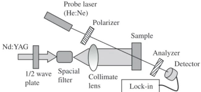
The photoalignment process was performed with the se-cond harmonic line of a polarized Nd-YAG (λ = 532 nm, P = 0.2 – 2.0 W). First, the laser beam was expanded with a spacial filter and than collimated by a lens. The light intensity measured at the sample position was about 180 mW/cm2. The photoinduced orientation of the azobenzene groups was follo-wed with a He-Ne probe laser, with the sample positioned be-tween crossed polarizers. A sketch of this setup is presented in Figure 2. The substrate coated with the photosensitive film is positioned between crossed polarizers and the irradiation is performed with the polarization direction at 45° from the
optical axis of both the polarizer and the analyzer. Therefore, before the Nd-YAG laser is turned on, the light intensity of the probe beam measured by the photodetector is minimum, and when the Nd-YAG laser is turned on the transmitted in-tensity of the He-Ne probe beam starts to increase due to the orientation of the azo-chromophores.
In the experiments with LC we used the 4-cyano-4’-n-pentylbiphenyl (5CB - Merck). All the experiments were per-formed at room temperature.
Results and Discussion
The pressure of the tip during the writing process is an important parameter to control. It is reported that when the illuminated tip touches softly the surface, a hill is formed along the writing line, which is associated to the mass trans-port due to the light intensity gradient from the middle to the edge (see Figure 1). However, for a stronger pressure, it is observed the formation of a channel along the writing line. The results indicated that even in the second case the process is induced by the light, because for a scanning with the same pressure of the tip, but with the laser beam off, no changes in the topography were observed[16].
The effect of irradiation time on the formation of SRGs can be investigated by controlling the time of scanning a line, i.e., the speed of scanning (v). This parameter is obtained by dividing the length of one line by the line scanning time, v is given in µm/s.
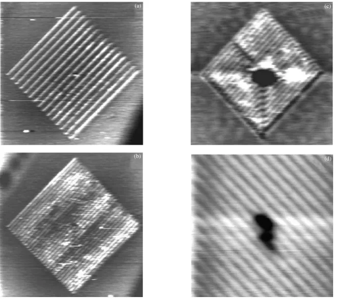
In Figure 3a we present an image of a writing area (60 x 60) µm2 with 15 lines, where it is possible to see a pe-riodic structure (p = 4.0 µm) with hills about 27 nm high. By increasing the number of lines to 30, a well defined SRG with period p = 2.0 µm and amplitude a = 10 nm was obtained, see Figure 3b. In Figure 3c a SRG was inscribed in a region of (10 x 10) µm2 with p = 0.5 µm and a = 7 nm. The gratins of Figures 3a, 3b and 3c were inscribed in the same conditions: pressure of the tip and v = 0.5 µm/s. One can notice that in this case the reduction of the amplitude is related only to the decreasing of the lines spacing and it seems to be caused by the volume of material transported to the center of the line. We assume that when the lines are too close the inscription of a second line removes material from a previous neighbor inscri-bed hill. Figure 3d shows in details a SGR with p = 1.0 µm and
a = 10 nm; it was inscribed in a region of (100 x 100) µm2 with
Figure 1. Scheme of the propagation of light through the SNOM cantilever.
x
Light sensitive film
Light intensity SNOM cantilever
Near field
hv
hv
Figure 2. Experimental setup for the photoalignment process.
1/2 wave plate
Spacial
filter Collimate lens Probe laser (He:Ne)
Polarizer
Sample
Analyzer Detector
Bechtold, I. H. et al. - Inscription of local surface relief gratings
Polímeros: Ciência e Tecnologia, vol. 16, nº 4, p. 319-322, 2006 321
100 lines and v = 1.7 µm/s. The black spot in the middle of Fi-gures 3c and 3d are holes created by the approach of the tip.
From the results presented above, it is clear that this me-thod allows the inscription of SRGs, made from lines smaller than the wave length of used light, with small periodicities and in small, well-defined regions of the surface.
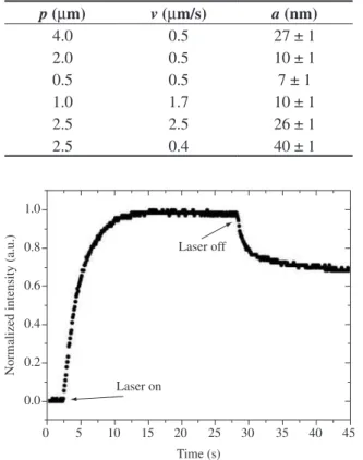
In order to check the effect of the irradiation time on the amplitude of the gratings, we inscribed SRGs with a fixed period p = 2.5 µm and two distinct scanning speeds,
v1 = 2.5 µm/s and v2 = 0.4 µm/s. The resulting amplitudes are
a1 = 26 nm and a2 = 40 nm, respectively. Although v2 is al-most one order of magnitude smaller than v
1, a2 is almost the double value of a1. It is reported in the literarure that there is a saturation in the inscription efficiency of the SRGs with the exposure time, depending on absortion of the polymer for the particular wavelegth used in the inscription process and also on the intensity of the incident beam[20]. This saturation is associated with the maximum value the amplitude can reach.
Close to the saturation, the behavior of the inscription effi-ciency versus time is no more linear, and would explain the above results. The relation between p and v and the resulting value of a can better be seen in Table 1.
LC cells were fabricated using these substrates and with a polarized microscope we could observe a homogeneous alignment along the channels direction, indicating that these treatments can be used to orient LCs. The azimuthal ancho-ring energy (Wφ) of these substrates was estimated with the Berreman’s equation using the morphological parameters of the gratings[15]. The obtained values are in the range of low anchoring energies (Wφ < 10-7 J/m2), but of course these values can be increased by increasing the amplitude of the gratings.
The photoalignment process due to the incidence of linear polarized light on the film was examined with the experimen-tal setup shown in Figure 2. The variation of the light inten-sity captured by the photodetector as a function of the irra-diation time is presented in Figure 4, where it is possible to
Figure 3. Structures inscribed with the SNOM in a region of (60 x 60) µm2: a) 15 lines about 27 nm high, b) 30 lines resulting in a well defined SRG with
pe-riod p = 2.0 µm and amplitude a = 10 nm; c) local SRG inscribed in a region of (10 x 10) µm2 with p = 0.5 µm and a = 9 nm; at this three gratings the scanning speed was the same, v = 0.5 µm/s; and d) details of a grating with p = 1.0 µm and a = 10 nm, it was inscribed with v = 1.7 µm/s.
(c)
(d) (a)
Bechtold, I. H. et al. - Inscription of local surface relief gratings
322 Polímeros: Ciência e Tecnologia, vol. 16, nº 4, p. 319-322, 2006
observe that the pDR1M has a fast photoalignment process, the saturation was achieved after approximately 10 s. When the Nd-YAG laser was turned off, a relaxation process (to approximately 70% of the maximum transmitted intensity) is observed, which is common for these materials.
The azimuthal anchoring energy (Wp) induced to the LC due to the alignment of the azo-dyes groups was estimated with the hybrid twisted cell method, using a rubbed Polyvinyl Alcohol (PVA) film in one side and a homogenous photoa-ligned pDR1M at the other side[21]. In a polarized light mi-croscope we observed a texture consistent with a total twist angle, indicating that the planar alignment induced to the LC present strong anchoring properties and of the same order of magnitude as the rubbed PVA (Wp = 1.5 x 10⁻⁵ J/m2)[22].
Conclusions
We presented a new method for locally inscription of SRGs using a SNOM, where it was observed that the amplitude of the gratings depends not only on the scanning speed, but also on the lines spacing. The photopolymer here investigated (pDR1M) present good properties for LCs applications: fast photoalignment process and strong azimuthal anchoring ener-gy. It is important to emphasize that the method of using lo-cal SRGs for LC alignment present advantages over the other existing method of nanorubbing a polyimide substrate with an AFM tip[23], because the gratings can easily be erased and a new inscription can be done, as reported in previous works[16].
Acknowledgments
I.H. Bechtold acknowledges FAPESP for the financial su-pports for his research stay in Potsdam, Germany, and thanks the University of Potsdam for its hospitality. Part of this work was supported by IMMP/MCT.
References
1. Nuyken, O.; Scherer, C.; Baindl, A.; Brenner, A. R.; Dahn, U.; Gärtner, R.; Kaiser-Röhfich, S.; Kollefrath, R.; Matusche, P. & Voit, B. - Prog. Polym. Sci., 22, p. 22 (1997).
2. Dhanabalan, A.; Mendonça, C. R.; Balogh, D. T.; Misoguti, L.; Constantino, C. J. L.; Giacometti, J. A.; Zilio, S. C. & Oliveira Jr., O. N. - Macromolecules, 32, p. 5277 (1999).
3. Stracke, A.; Wendorff, J. H.; Goldmann, D.; Janietz, D. & Stiller, B. - Adv. Mat., 12, p. 282 (2000).
4. Maack, J.; Ahuja, R. C.; Mobius, D.; Tachibana, H. & Matsumoto, M. - Thin Solid Films, 242, p. 122 (1994).
5. Nikolova, L.; Todorov, T.; Ivanov, M.; Andruzzi, F.; Hvilsted, S. & Ramanujam, P. S. - Appl. Opt., 35, p. 3835 (1996).
6. Rochon, P.; Batella, E. & Natansohn, A. - Appl. Phys. Lett., 66, p. 136 (1995).
7. Vismanathan, N. K.; Kim, D. Y.; Bian, S.; Williams, J. M.; Liu, W.; Li, L.; Samuelson, L.; Kumar, J. & Tripathy, S. K. - J. Mat. Chem., 9, p. 1941 (1999).
8. Labarthet, F. L.; Bruneel, J. L.; Buffeteau, T.; Sourisseau, C.; Huber, M. R.; Zilker, S. J. & Bieringer, T. - Phys. Chem. Chem Phys, 22, p. 5154 (2000).
9. Natansohn, A. & Rochon, P. - Chem. Rev., 102, p. 4139 (2002). 10. Bian, S.; Williams, J. M.; Kim, D. Y.; Li, L.; Balasubramanian, S.;
Kumar, J. & Tripathy, S. K. - J. Appl. Phys., 86, p. 4498 (1999). 11. Oliveira Jr., O. N.; Li, L.; Kumar, J. & Tripathy, S. K. - “Surface Relief
Gratings on Azobenzene-Containing Films”, in: Photoreactive Or-ganic Thin Films, Academic Press, CA, San Diego (2002). 12. Thiegui, L. T.; Barberi, R.; Bonvent, J. J.; Oliveira, E. A.; Giacometti, J.
A. & Balogh, D. T. - Phys. Rev. E, 67, p. 041701 (2003).
13. Newsome, C. J.; O’Neill, M.; Farley, R. J. & Bryan-Brown; G. P. - Appl. Phys. Lett., 72, p. 2078 (1998).
14. Kim, M.-H.; Kim, J.-D.; Fukuda, T. & Matsuda, H. - Liq. Cryst., 27, p. 1633 (2000).
15. Berreman, D. W. - Phys. Rev. Lett., 28, p. 1683 (1972).
16. Stiller, B.; Karageorgiev, P.; Buchsteiner, A.; Geue, Th.; Henneberg, O.; Brehmer, L.; Natansohn, A. & Hollricher, O. - Adv. Opt. Mat., 5122, p. 176 (2003);
Stiller, B.; Karageorgiev, P.; Geue, Th.; Morawetz, K.; Saphianni-kova, M.; Mechau, N. & Neher, D. - Phys. Low-Dim. Struct., ½, p. 129 (2004).
17. Stiller, B.; Geue, T.; Morawetz, K. & Saphiannikova, M. - Journal of Microscopy, 219, p. 109 (2005).
18. Geue, T. M.; Schultz, M.; Grenzer, J.; Pietsch, U.; Natansohn, A. L. & Rochon, P. L. - J. Appl. Phys., 87, p. 7712 (2000).
19. Alpha-SNOM user manual, WITec GmbH Germany, Hövelsinger Weg D89081 ULM.
20. Barrett, C. J.; Natansohn, A. L. & Rochon, P. L. - J. Phys. Chem., 100, p. 8836 (1996); Kulikovska, O.; Gharagozloo-Hubmann, K. & Stumpe, J. - Adv. Opt. Mat., 4802, p. 85 (2002).
21. Bryan-Brown, G. P. & Sage, I. C. - Liq. Cryst., 20, p. 825 (1996). 22. Schadt, M.; Schmitt, K.; Kozinkov, V. & Chigrinov, V. G. - Jpn. J. Appl.
Phys., 31, p. 2135 (1992).
23. Pidduck, A. J.; Haslam, S. D.; Bryan-Brown, G. P.; Bannister, R. & Kitely, I. D. - Appl. Phys. Lett., 71, p. 2907 (1997).
Enviado: 15/05/06 Reenviado: 08/08/06 Aprovado: 15/08/06
Table 1. Values of the obtained grating amplitude a for different
combina-tions of p and v.
p (µm) v (µm/s) a (nm)
4.0 0.5 27 ± 1
2.0 0.5 10 ± 1
0.5 0.5 7 ± 1
1.0 1.7 10 ± 1
2.5 2.5 26 ± 1
2.5 0.4 40 ± 1
Figure 4. Shows the photoalignment process of the pDR1M, transmitted
light intensity vs. irradiation time. 1.0
0.8
0.6
0.4
0.2
0.0
Normalized intensity (a.u.)
0 5 10 15 20 25 30 35 40 45
Time (s) Laser off