Journal of Engineering Science and Technology Review 8 (6) (2015) 49 – 53 Special Issue on Simulation of Manufacturing Technologies
Conference Article
Numerical Simulation of Residual Stresses in Linear Friction Welded Joints
R. Nikiforov1, A. Medvedev1, E. Tarasenko1 and A.Vairis2
1Ufa State Aviation Technical University, Ufa, Russian Federation
2 Technological Education Institute of Crete, Heraklion, Greece
Received 2 September 2015; Accepted 8 September 2015
___________________________________________________________________________________________
Abstract
A thermo-mechanical model of linear friction welding has been developed. The temperature distribution during the heating process was determined using a one-dimensional model. The distribution of temperature and stress field during the forging phase was determined by solving the coupled problem in ANSYS. The model allows to predict the effect of welding parameters on the stress field, whereas modeling data are consistent with the residual stresses in welded joints of the Ti6Al4V alloy obtained during the experiment.
Keywords:
linear friction welding, numerical modeling, temperature field, stress-strain state, residual stresses, titanium alloys.
__________________________________________________________________________________________
1. Introduction
Residual stresses have a significant impact on the cyclic and dynamic strength, and study of their forming mechanism is of paramount importance. During the last decade there have been published several studies on the residual stress distribution during linear friction welding, such as [1, 2]. In this paper a model was developed to assess the influence of LFW parameters on the residual stress field in welded joints. Existing numerical models of LFW are difficult to use to that effect while not providing sufficient accuracy of results [3,4]. Since residual stresses generate during cooling of hot metal it is allowable to use numerical modeling only for the forging stage. The temperature field at the end of the heating stage can be determined without the use of finite element analyses [5]. This approach can significantly reduce the complexity of calculations.
2. Description of the numerical model
A numerical model was developed in the finite element package ANSYS Multiphysics. The indirect method was used to solve the thermal and mechanical problem were calculations are performed separately.
The numerical analysis estimation f temperature fields in LFW was performed for a one-dimensional model, which has been described in detail in [4, 5].
The coefficient of thermal conductivity was assumed to be 0.17 W/cm·K, volumetric heat capacity was assumed to be 2.8 J/cm3·K, surface heat transfer coefficient was set to 100 W/m2·K. Thermal cycles were approximated by polynomial functions in STATISTICA and loaded as thermal load histories applied to components of the 3D
model.
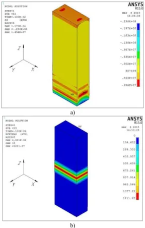
The calculation of residual strain was based of the non-isothermal flow theory using the parametric design language APDL. The load was applied in time steps in the transient state for use with the iterative method of Newton-Raphson to calculate strain during each step (allowing no more than 10 iterations per step). The deformation and plastic material behavior models met the criteria of the von Mises yield multilinear kinematic hardening model (MKIN) incorporating the Baushinger effect. Estimating thermal strain was carried out in 3 stages: 1) at the beginning the stress-strain state of the samples during clamping in the welding machine was estimated; 2) following that stage the temperature field was applied on the stress-strain state of the samples as a load [5]; 3) and finally the welded joint was released from the clamps of the LFW machine. Numerical analyses were carried out for different forging pressures values Pff= 0 kN, Pff = 25 kN and Pff = 50 kN. Fig. 1 shows prestressed state of the samples in the clamps, and the distribution of temperature at Pff = 25 kN.
In order to estimate residual stresses 185 SOLID 8-nodal elements were used with a finite element mesh size in the weld zone and the heat affected zone of a = 0.5 mm and in the zone of the parent material of – a = 1.0 mm. Fig. 2 shows the distribution of stress components σx and σy in the welded sample after removal of forging force of Pff= 25 kN.
3. Model verification and analyzing modeling results
In order to verify the model results from experiment were used, as described in [6]. Residual stresses were calculated for VT6 joints (Russian equivalent of Ti6Al4V) samples with a 26×14 mm cross section, welded with different values of forging force (0.25 and 50 kN). The residual stress level in the longitudinal (x) and transversal (y) directions was calculated when the B and C dimensions were changed and the B×C×e area was studied (Fig. 3).
______________
* E-mail address: [email protected]
ISSN: 1791-2377 © 2015 Kavala Institute of Technology.
All rights reserved.
J
estr
JOURNAL OF Engineering Science andTechnology Review
R. Nikiforov, A. Medvedev, E. Tarasenko and A.Vairis / Journal of Engineering Science and Technology Review 8 (6) (2015) 49 - 53
51 a)
b)
Fig.1. σz distribution in the first stage of modeling (a) and temperature distribution along the Z axis (b)
a)
b)
Fig. 2.Stresses σx (a) and σy(b) at the joint e for Pff = 25 kN (b)
Experimental procedure included the following steps : 1) linear friction welding of samples; 2) mechanical treatment of the welded samples where the flash was removed and the correct B and C dimensions were ensured; 3) measuring B and C sides; 3) cutting the B×C×e area to release residual stresses; 4) measuring B and C ; 4) processing experimental results.
Fig. 3. Sample details.
The analysis of experimental results suggested that changes in the size of B and C are caused by internal forces:
dz B P dz C P e y y e x
x = ∫ = ∫
2 0 2 0 2 ,
2 σ σ (1)
Px and Py can be calculated:
⎟ ⎠ ⎞ ⎜ ⎝ ⎛ Δ + Δ − = ⎟ ⎠ ⎞ ⎜ ⎝ ⎛ Δ + Δ − = B B C C eCE P C C B B eBE
Py x µ
µ µ
µ2 1 2
,
1 (2)
where E – elasticity modulus, ΔB – change in B, ΔC – change in C, µ – Poisson's ratio.
It is necessary to have a range of measurements for each sample with different values e1, e2, ..., ek to identify stress distributions along the z axis. In this case, the values of P1,
P2, ..., Pk, calculated by (2), can be used to estimate average stresses σ1, σ2, ..., σk in the areas e1, e2–e1 ... ek–ek-1:
(
)
(
e e)
BP P C e e P P i i i y i y i y i i i x i x i
x − ⋅
− = ⋅ − − = − − − − 1 ) 1 ( ) ( ) ( 1 ) 1 ( ) ( )
( ,σ
σ (3)
For samples, welded with no forging stage in [6], the cut out areas measured were with e=1, ..., 12 mm. Values estimated in the absence of a forging stage, with equations (2) and (3) are shown in Figure 4 with the symbol (x). The standard deviation of the measurements was 18% of the maximum level for the both measured stress components. Solid lines on the same graphs show modeling results.
For samples, welded with a 25 and 50 kN forging force, cut out areas were with e=3 mm. Results of modeling (solid lines) and experimental points (x) are shown in fig.5-6.
R. Nikiforov, A. Medvedev, E. Tarasenko and A.Vairis / Journal of Engineering Science and Technology Review 8 (6) (2015) 49 - 53
52
a)
b)
Fig. 4.σx (a) and σy (b) distribution along the z axis (no forging case)
When the forging phase is included in the welding cycle the value of the residual stress tensor components σx
and σy is reduced while σx exceed the value σy as seen in Fig.
4-6.The calculated values σxmax and σymax for the entire range of Pff studied were lower than the experimental ones.
Deviations of σxmax do not exceed 36% (100 MPa) while the biggest difference between calculated and experimental results corresponded to the welding regime with the maximum forging force. Deviations of σymax reach 60% (144 MPa) which was in the case of Pff = 50 kN which
corresponds to the minimum deviation between calculated and experimental values.
It should be pointed out that the considerable variation in measured values (standard deviation for ΔB and ΔC was 18% of the mean values) cannot be explained by experimental error solely.
The calculated length of the tensile stresses zone was 3.4 mm for σx and 2.3 mm for σy. Thus a place where tensile stresses transform to compressed stresses corresponds to areas heated to 700–800°C. The experimentally determined size of the tensile stress zone is 8 mm which corresponds to an area heated above 230 ° C. It should be noted that the small range of size templates used makes it difficult to construct diagrams with large stress gradients in the high temperature zone. However, deviations between σxand σy tensile stresses are not only due to the statistical error in the experimental evaluation of stress, but also to modeling errors: the selected heating scheme; and/or the inaccuracy of temperature-dependent material properties.
a)
b)
Fig. 5.σx (a) and σy (b) distribution along the z axis (for Pff=25 kN)
a)
b)
R. Nikiforov, A. Medvedev, E. Tarasenko and A.Vairis / Journal of Engineering Science and Technology Review 8 (6) (2015) 49 - 53
53 4. Conclusions
1. Comparing calculated and experimental data shows that the developed numerical model can qualitatively predict the distribution and dependence from welding parameters of residual stresses in joints produced with linear friction welding.
2. The maximum value of the σxand σy tensile stress is inversely dependent on forging force.
3. The discrepancy between the σxand σytensile stresses is caused by not only the statistical error in the experimental evaluation of stress, but also by modeling errors: the selected heating scheme; and (or) the inaccuracy of temperature-dependent material properties employed.
Acknowledgments
This work was produced during the joint project between USATU (Ufa State Aviation Technical University) and UMPO (Ufa Engine Industrial Association) with title “Elaboration and industrial development of high-precision shaping coordinated technologies and superficial hardening of responsible details from Al-alloys with heightened constructional energy efficiency”, implemented under the contract №40/10-30976 sponsored by the Ministry of Education and Science of the Russian Federation (contract №02.G25.31.0010 between UMPO and the Ministry of Education and Science of the Russian Federation) through the Resolution of the Russian Federation Government № 218 from April 9, 2010.
___________________________ References
[1] M.R. Daymond, N.W. Bonner N., “Measurement of strain in a titanium linear friction weld by neutrondiffraction” Physica B-Condensed Matter, vol.325, p.130–137, 2003.
[2] J. Romeroa,M.M. Attallah, M. Preuss, M. Karadge, S.E. Bray, “Effect of the forging pressure on the microstructure and residual stress development in Ti–6Al–4V linear friction welds”, Acta Materialia, vol.57, p.55-82 (2009).
[3] A. Vairis, M. Frost, “Modelling the linear friction welding of titanium blocks”, Materials Science and Engineering A292, 8 (2000).
[4] S.К. Kiselyeva, А.М. Yamileva, М.V. Karavaeva, I.Sh.
Nasibullayev , V.М. Bychkov, А.Yu. Medvedev, А.V. Supov, F.F.
Musin , I.V. Alexandrov, V.V. Latysh, “Computer modelling of linear friction welding based on the joint microstructure”, Journal of Engineering Science and Technology Review, vol.5, issue.3, p.44-47, 2012.
[5] A. Medvedev, A. Vairis, R. Nikiforov and A. Supov, “Energy balance of the linear friction welding process”, Journal of Engineering Science and Technology Review, vol.5, issue.3, p.20-24, 2012.