Metallurgy and materials
Metalurgia e materiais
Abstract
This paper presents a study about the fracture mechanism of a ferritic stainless steel (UNS S44400 type) during a tensile test. The applied materials for the experi-mental procedures were 25 specimens of the steel, machined in the rolling direction. Each specimen was submitted to standard polishing procedures. One of the samples, in the original state, was structurally characterized by relected light optical micros-copy. The other samples were submitted to tensile tests with a constant displacement rate. Three samples were tested until failure (complete tests) and the others just until speciic strain values, when the tests were interrupted and the samples were character-ized by using optical and scanning electron microscopy. The main objective of these characterizations was to evaluate the structural damage evolution and to identify the fracture mechanism for the tested conditions. A methodology to quantify the dam-age evolution by surface roughness, identiied by optical microscopy, was proposed. A new index - Damage by Diffuse Relection Index (DRI) - was proposed to quantify the damage evolution in function of the specimen deformation. It was possible to conirm the ductile behavior of the studied steel and that the main fracture mechanism was the traditional dimpled rupture.
Keywords: tensile test, failure mechanism, ductile fracture, damage evolution. Geraldo Lúcio de Faria
Doutor, Professor Adjunto
Universidade Federal de Ouro Preto - UFOP Escola de Minas
Departamento de Engenharia Metalúrgica Ouro Preto – Minas Gerais – Brasil [email protected]
Leonardo Barbosa Godefroid
Doutor, Professor Associado
Universidade Federal de Ouro Preto - UFOP Escola de Minas
Departamento de Engenharia Metalúrgica Ouro Preto – Minas Gerais – Brasil [email protected]
Fernando Victor Nery
Estudante de Graduação
Universidade Federal de Ouro Preto – UFOP Escola de Minas
Departamento de Engenharia Metalúrgica Ouro Preto – Minas Gerais – Brasil [email protected]
Damage evolution
in a tensile specimen
of a ductile stainless steel
http://dx.doi.org/10.1590/0370-44672015690183
1. Introduction
Ductile fracture is a common mode of fracture in engineering alloys. It has also been known as a dimpled, ibrous, or plastic fracture. A fracture by this mode usually involves the absorption of a large amount of energy. Ductile fracture is a non-trivial issue that affects the workabil-ity (formabilworkabil-ity) of engineering materials (Lassance et al., 2007). The accurate
prediction of a material’s ductile fracture is thus of practical importance in the design and optimization of processes and products. There have been many reviews dealing with ductile fracture. Among them are that of Rosenield (1968), Low Jr. (1968), Broek (1971), Schwalbe (1977), Howard/Willoughby (1981), Wilsdorf (1983), Leslie (1983), Van Stone et al. (1985), Godefroid/Bastian (1989), Li et al. (2011), and Lou/Huh (2013).
From a microscopic viewpoint, ductile fracture is the integral
manifesta-tion of three stages: nucleamanifesta-tion of internal voids during plastic low, the growth of these voids with continued deformation, and inally their coalescence to produce complete rupture. The details of these three stages may vary widely in different materials and with the existing stress state during deformation. Similarly, the fractographic appearance of the final fracture surface is inluenced by these same factors. These three procedures have been extensively studied experimentally, analytically and numerically.
The voids nucleation may occur in systems containing second-phase particles, by particle/matrix interface separation or by particle cracking. The interaction of slip and a second phase, usually less deform-able than the matrix, leads to regions of highly localized stress, which cause crack-ing of the particle or interface decohesion (Bluhm/Morrissey (1965), Gladman et al.
(1971), Gurland (1972), Cox/Low (1974), Argon et al. (1975)). The void nucleation
can also occur at blocked slip bands in the absence of second-phase particles in systems of highly restricted, anisotropic deformation. Voids are formed when an intense deformation band impinges on a grain or twin boundary, and because of the limited slip systems the adjacent crystal is unable to accommodate the shear defor-mation. The boundary, which contains no inclusions, is irst offset until the stresses at the leading edge become so great that the material separates and produces a void (Thompson/Williams (1977), Van Stone et al. (1978), Wilsdorf et al. (1986)).
Local stress concentrations due to strain incompatibilities in two different phases interfaces, like dual-phase steels, are also reported to cause void nucleation (Shen et al. (1986), Suh et al. (1997), Ahmed et al.
et al. (2011)).
There are at least two distinct mech-anisms of stable void growth. In one, the cavity growth is controlled by plastic low of the material matrix that surrounds the void-nucleating phase. In the second case, the irst type of void growth is assisted by decohesion at smaller second-phase particles during the deformation process. The smaller second-phase particles can either be from the lower end of the size distribution of a single particle type or from a totally different phase having its own characteristic size distribution (Flo-reen/Hayden (1970), Cox/Low (1974),
Thomasson (1985)).
Void coalescence occurs by either void impingement or by the void-sheet process. In the irst case, coalescence of inclusion-nucleated voids can occur by the necking down of the matrix between voids until the ligament has no cross-sectional area. In the latter case, voids nucleate at a population of dispersed phases, generally smaller than the inclusions which nucle-ated the primary voids. The formation of void sheets aborts the otherwise stable void-growth process and thus diminishes toughness and ductility (Greenield/Mar-golin (1972), Brown/Embury (1973), Cox/
Low (1974), Weck/Wilkinson (2008). In this context, this work aims to study the evolution of plastic de-formation and microstructure damage in ferritic stainless steel samples of UNS S44400 grade (APERAM, 2012), through the tensile test. For this purpose, the surface of the samples was polished and properly observed with the use of optical microscopy and scanning elec-tron microscopy. A single index related to the “strain roughness” of the samples is being proposed to characterize the mechanical behavior of the material and the damage evolution.
2. Material and experimental methods
A hot rolled sheet of an UNS S44400 ferritic stainless steel with 0.5mm thick-ness was supplied by the company APER-AM South America. Its chemical compo-sition was obtained using a THERMO SCIENTIFIC model ARL-4460 optical emission spectrometer. The microstruc-ture was revealed with a modiied Vil-lela reagent (5g of picric acid, 100ml of
ethylic alcohol, and 6ml of hydrochloric acid), and observed in a LEICA optical microscope coupled to a digital camera for image acquisitions and controlled by a Q-WIN software.
Tensile specimens with continuous radius between ends were prepared with the following dimensions: total length = 50mm; minimum width = 12.5mm;
thickness = 0.5mm. Figure 1 shows an example of this geometry. This type of geometry was chosen to facilitate the monitoring of strain along the gage length and to ensure the fracture in the center of the specimen. The specimens had three holes in their heads, for cou-pling with the grips of the mechanical testing machine.
Figure 1
Tensile specimen geometry.
In order to adjust the tensile speci-mens for visual monitoring of their de-formation during the tests, the surfaces were conveniently prepared by grinding and polishing as the usual metallographic practice. Specimens were sanded in special sandpapers from 400mesh to 1200mesh, and polished with alumina aqueous sus-pension with particle average size of 1μm and diamond paste with particle average size of 0.25μm.
Tensile tests were conducted on a 10ton MTS-810 servo-hydraulic testing machine interfaced to a computer for machine control and data acquisition. All tests were executed with a 5mm/min displacement rate. Three specimens were submitted to the complete tensile test, until fracture occurrence, to obtain the main mechanical properties of the steel. The remaining specimens were submitted to
incomplete tensile tests, been interrupted with different strain levels: 1.2%, 9.7%, 12.2%, 14% and 16%.
After the tensile tests, all the speci-mens were analyzed with the LEICA opti-cal microscope. The Q-WIN software was used to monitor the deformation process and to measure the “strain roughness” of the tested specimens. An Inspect-S50 scanning electron microscope was also used to characterize the supericial dam-age evolution and to conirm the ductile mechanism of the steel fracture.
The quantitative parameter pro-posed to characterize the damage evo-lution during the deformation process was named Diffuse Relection Index (DRI). This index is related to the supericial roughness occurrence that increases with the strain level of the tensile specimen. Before the polished
specimen strain (very low roughness), in an observation at the optical micro-scope with magniication of 200X, it is possible to observe that all the points in the ield view were in focus, because all of them had a distance from the objec-tive lens inside the ield depth distance (Figure 3). However, as the specimens were strained and the roughness has increased, the topographic changes on sample surface create trough and crest areas that go out from the ield depth distance, getting out of focus with a strong diffuse relection proile.
exempliies this procedure. Ten images with 200X magniication were captured at the middle of the strained specimens
and the not focused areas were auto-matically identiied and blue painted. Using the Q-WIN software, the blue
areas were quantiied by image analysis and the DRI index was calculated ap-plying Equation 1.
DRI (%) =
Area out of focus
Image total area
x 100
(1)
Figure 2 Q-Win Software application to determine the strain roughness of a tensile specimen. Blue regions are the not focused areas.
3. Results and discussion
Table 1 presents the chemical com-position of the studied stainless steel. This chemical composition meets the manufacturer's speciication (APERAM,
2012). Only the chromium content is slightly below the specified (17.5%-18.5%). It is interesting to note the presence of Mo, which improves the
cor-rosion resistance, and the bi-stabilization by Ti and Nb. The very low content of nickel gives this material a very competi-tive price.
C Mn P S Si Ni Cr
0.007 0.16 0.034 0.002 0.47 0.19 16.7
Mo Al Cu V Nb Ti Co
1.92 0.01 0.06 0.05 0.22 0.18 0.03
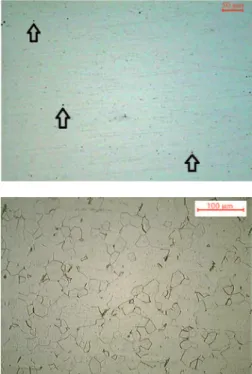
Figure 3 presents an image (optical microscope) of a sanded and polished surface of the studied steel, without etch-ing. It is possible to see a ine distribution
of inclusions (small black points). Cracks and other volumetric defects, which could affect the structural integrity of steel, were not observed. Figure 4 presents the ferritic
structure of the studied steel after etching with the modiied Villela reactive. It is possible to observe a heterogeneous ferritic grain size distribution.
Table 1 Chemical composition of the used stainless steel (wt%).
Figure 3 Microstructure of steel UNS S44400 without chemical attack.
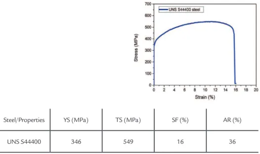
Figure 5 presents the conventional tensile test curve with average values ob-tained from three tests. Table 2 presents the main properties obtained from this test for this steel. It is important to comment that
the obtained total strain is below the value speciied by the manufacturer (APERAM, 2012), because the specimens used in this work do not followed the ASTM E8 stan-dard for tensile test. The sheet was machined
with a continuous concordance radius aim-ing to promote a strong stress concentration in the middle of the specimen. The specimen type was inspired by the ASTM E466 for fatigue test on metallic materials.
Figure 5
Tensile curve of the studied steel.
Table 2
UNS S44400 average mechanical properties (YS - Yield Strength, TS - Tensile Strength, SF – Strain to fracture, AR - Area Reduction).
Steel/Properties YS (MPa) TS (MPa) SF (%) AR (%) UNS S44400 346 549 16 36
The lateral surface of all tested specimens was analyzed by optical microscope. Figures 6-11 show the corresponding micrographs. It is
possible to see that the increase of deformation in the specimen causes a greater roughness on its surface. There is also an increase in the quantity and
thickness of slip lines, arising from the slipping of crystallographic planes in the grains of the material.
Figure 6
Specimen 1.2% strained.
Figure 7
Specimen 9.7% strained.
Figure 8
Figure 9 Specimen 14% strained.
Figure 10 Specimen 15.5% strained.
Figure 11 Specimen 16% strained.
Figure 12 presents the damage evolution indirectly measured by the Diffusion Relection Index (DRI) as a function of specimen deformation, using the surface roughness of the specimens. The specimen without deformation (0%) corresponds to the as-received material, so it does not present damages. The 1.2% de-formed specimen also did not present signiicant damages. Specimens with higher deformation presented signii-cant supericial damages, especially for deformations higher than 10%.
From this level of strain, the tensile strength of the material is being achieved, the necking process begins to operate in the specimen, and local roughness is evident.
Figure 13 shows an example of the necking development, for 14% of deformation. No signiicant differences were observed between samples with 15.5% and 16%, due to the evolution stage of necking caused by the advanced degree of microvoids coalescence. It is pos-sible to observe that the higher the
deformation, the higher the standard deviation obtained in experimental procedures. This occurs due to the higher deformation, more intense and localized is the deformation effects on surface (necking). As the proposed method for DRI determi-nation consists in scanning different ields of view under an optical micro-scope; if the deformation signals are more localized, the DRI measured for each iled is not very similar. As a consequence, the standard devia-tion is higher.
Figure 13
Superficial damage in the necking
region of a tensile specimen strained by 14%.
Samples submitted to higher deformations were analyzed in a scanning electron microscope. Figures 14-17 present images obtained with SEM for 9.7%, 12.2%, 14% and 16% strained specimens, respectively.
Figure 14 shows sets of defor-mation lines, each set with a speciic orientation. This is due to each ma-terial grain presenting a well deined crystalline orientation and a prefer-ential slip plan that may slip accord-ing to its position at solid bulk and applied force.
Figure 15 presents deformation lines and microvoid nucleation (red cicles). This Figure corresponds to 12.2% strained specimen, which is already plastic deformed in a non-uniform ield. It is possible to note that for the studied stainless steel, the microvoid nucleation starts mainly in the deformation lines. Other researchers as Puttick (1959), Rogers (1960), Chen (1961) and Beevers & Honeycomb (1962) founded similar results for other metallic materials. They pointed out
the deformation lines as a potential structural defect where voids can preferentially nuclei.
Figure 16 (14% strained speci-men) shows large voids, that are formed by the coalescence between smallers voids, as described in literature.
Figure 17 (16% strained speci-men) presents a crack iniciation due to microvoids coalescence. These obser-vations conirm that the ductile frac-ture mechanism is nucleation, growth and coalescence of microavoids, in accordance to literature.
Figure 14
Specimen 9.7% strained.
Figure 15
Figure 16 Specimen 14% strained.
Figure 17 Specimen 16% strained.
Aiming to characterize the studied steel fracture and prove the relationship between microstructural damage evolu-tion and ductile fracture mechanism, all
tested samples until failure were analyzed in a scanning electron microscope for a fractograph analysis. Figure 18 presents images of fracture surfaces where dimples
are present, conirming the mechanism of nucleation, growth and coalescence of microvoids as the main way of the ductile fracture in UNS S44400 steel.
Figure 18 Fractographies of tensile test specimens. SEM - 2000X.
4. Conclusions
The proposed method for dam-age evaluation by the DRI index was satisfactory because it allowed to quantify and to compare different damage intensities as a function of specimen strain.
The proposed DRI index can be a potential tool, with easy application and low experimental cost, associated to optical and electronic microscopy, to characterize the microstructural
damages in different metallic materi-als as a function of their strains.
The proposed DRI index can be tested as a tool to describe and under-stand the specimen damages caused by other mechanical damages, like fatigue. This method can be tested to describe de damage evolution as a function of material fatigue life, relating structural aspects with crack nucleation and propagation.
5. Acknowledgements
The authors would like to thank APERAM South America for providing the material for the present research.
6. References
AHMED, E., TANVIR, M., KANWAR, L.A., AKHTER, J.I. Journal of Materials Engineering and Performance, v.9, p. 306-310, 2000.
ARGON, A.S., IM, J., SAFOGLU, R. Cavity formation from inclusions in ductile fracture. Metallurgical Transactions, v. 6A, p. 825-837, 1975.
BLUHM, J.I., MORRISSEY, R.J. Fracture in a tensile specimen. In: INTERNATIO-NAL CONFERENCE ON FRACTURE, 1965. Japan. Proceedings of the First International Conference on Fracture. v.1, p.1739-1780, 1965.
BROEK, D. The role of inclusions in ductile fracture and fracture toughness. Engine-ering Fracture Mechanics, v. 5, p. 55-66, 1973.
BROWN, L.M., EMBURY, J.D. The initiation and growth of voids at second phase particles. The Microstructure and Design of Alloys. Cambridge: 1973. 5p. COX, T. B., LOW, J. R. An investigation of the plastic fracture of AISI 4340 and
18 Nickel-200 grade maraging steels. Metallurgical Transactions, v. 5A, p. 1457-1470, 1974.
ERDOGAN, M. The effect of new ferrite content on the tensile fracture behaviour of dual phase steels. Journal of Materials Science, v.37, p. 3623–3630, 2002. FLOREEN, S., HAYDEN, H.W. Some observations of void growth during the tensile
deformation of a high strength steel. Scripta Metallurgica, v. 4, p. 87-94, 1970. GLADMAN, T., HOLMES, B., McIVOR, I.D. Effects of second-phase particles on
strength, toughness, and ductility. The Iron and Steel Institute, 1971. 10p. GODEFROID, L. B., BASTIAN F. L. Uma análise crítica sobre modelos que envolvem
a inluência de inclusões na fratura dúctil. In: CONGRESSO ANUAL DA ABM, 44. 1989, Rio de Janeiro. Anais..., 1989. v. 1, p. 471-493.
GREENFIELD, M.A., MARGOLIN, A. The mechanism of void formation, void gro-wth, and tensile fracture in an alloy consisting of two ductile phases. Metallurgical Transactions, v. 3A, p. 2649-2659, 1972.
GURLAND, J. Observations on the fracture of cementite particles in a spheroidized 1.05%C steel deformed at room temperature. Acta Metallurgica, v. 20, p. 735-741, 1972.
HOWARD, WILLOUGHBY, A. A. Developments in Fracture Mechanics. Applied Science. v. 2, p.39-99, 1981.
KADKHODAPOUR, J., BUTZ, A., RAD, S. Z. Mechanisms of void formation du-ring tensile testing in a commercial dual phase steel. Acta Materialia, v. 59, p. 2574-2588. 2011.
KLASSEN, R.J., BASSIN, M.N., BAYONMI, M.R., WILSDORF, H.G.F. Materials Science and Engineering, v. 83, p. 39-44, 1986.
LASSANCE, D., FABREGUE, F., DELANNAY, F., PARDOEN, T. Micromechanics of room and high temperature fracture in 6XXX Alloys. Progress in Materials Science, v. 52, p. 52–129, 2007.
LESLIE, W.C. Inclusions and mechanical properties. Transactions of the Iron and Steel Society, v.2, p.1-24, 1983.
LI, H., FU, M.W., LU, J., YANG, H. Ductile fracture: experiments and computations. International Journal of Plasticity, v. 27, p. 147-180, 2011.
LOU, Y., HUH, H. Prediction of ductile fracture for advanced high strength steel with a new criterion: experiments and simulation. Journal of Materials Processing and Technology, v. 213, p. 1284-1302, 2013.
LOW, J. R. Effects of microstructure on fracture toughness of high strength alloys. Engineering Fracture Mechanics, v. 1, p. 47-53, 1968.
ROSENFIELD, A. R. Criteria for ductile fracture of two-phase alloys. Metallurgical Reviews, v.13, p. 29-40, 1968.
SCHWALBE, K.H. On the inluence of microstructure on crack propagation mecha-nisms and fracture toughness of metallic materials. Engineering Fracture Mecha-nics, v. 9, p. 795-832, 1977.
SUH, D., KWON, D., LEE, S., KIM, N.J. Metallurgical Transactions, v. 28A, p. 504–509, 1997.
SUH, D., KWON, D., LEE, S., KIM, N. J. Orientation dependence of microfracture behavior in a dual-phase high-strength low-alloy steel. Metallurgical Transactions A. v. 28, p. 504–509, 1997.
THOMASSON, P.F. Acta Metallurgica, v. 33, p. 1087-1095, 1985.
THOMASON, P. Three-dimensional models for the plastic limit-loads at incipient failure o f the intervoid matrix in ductile porous solids. Acta Metallurgica, v. 33, p. 1079- 1085. 1985 a
THOMPSON, A.W., WILLIAMS, J.C. Nuclei for ductile fracture in titanium. In: FOURTH INTERNATIONAL CONFERENCE ON FRACTURE, 1977. Ca-nada. Proceedings of the FOURTH INTERNATIONAL CONFERENCE ON FRACTURE, 1977. v.2, p.343-348.
VAN STONE, R. H., COX, T. B., LOW, J. R., PSIODA, J. A. Microstructural aspects of fracture by Dimple rupture. International Metals Reviews, v. 30, p. 157-179, 1985.
VAN STONE, R.H., LOW, J.R., SHANNON, J.L. Investigation of the fracture me-chanism of Ti-5Al-2.5Sn at cryogenic temperatures. Metallurgical Transactions, v.9A, p.539-552, 1978.
WECK, A., WILKINSON, D. Experimental investigation of void coalescence in me-tallic sheets containing laser drilled holes. Acta Materialia, v. 56, p. 1774–1784, 2008.
WILSDORF, H. G. F. The ductile fracture of metals: a microstructural viewpoint. Materials Science and Engineering, v. 59, p. 1-39, 1983.