Sigma Phase in Superduplex Stainless Steel: Formation, Kinetics and Microstructural Path
Gláucio Soares da Fonsecaa*, Phelipe Matias de Oliveiraa, Marília Garcia Dinizb, Dimitry
Valerievitch Bubnofa, José Adilson de Castroa
Received: June 8, 2016; Revised: October 24, 2016; Accepted: November 21, 2016
The superduplex stainless steels (SDSS) are widely used in chemical, oil and gas industries, to pipelines and storage material facilities. In welding process or working in temperature elevated, secondary
phases may appear in the form of precipitates, as the sigma phase (σ) which is an intermetallic compound.
This compound is harmful to the properties of steel, deteriorating its mechanical properties, such as decreasing corrosion resistance and toughness. In this paper it is analyzed the formation, kinetics and microstructural evolution of sigma phase in SDSS UNS S32750 after isothermal aging at 700ºC, 750ºC and 800ºC. In this work sigma phase kinetics is studied by JMAK theory and by two microstructural path descriptors, SV, interfacial area per unit of volume between sigma phase and austenite, and <λ>,
mean chord length of sigma, both in function of the VV, volumetric fraction of sigma, known in the literature as microstructural partial path (MP). The MP formulation is common in recrystallization studies, but so far has not been used in the sigma phase precipitation studies, being applied here for
the irst time. The results indicated that the sigma phase nucleates by site saturation with anisotropic
linear impingement. This means that sigma phase nucleates on edges.
Keywords: Superduplex Stainless Steel, Sigma Phase, Kinetics, Microstructural Path, Impingement
* e-mail: [email protected]
1. Introduction
The superduplex stainless steels (SDSS) are widely used in chemical industry, oil and gas, in the pulp industry, applied to pipelines and storage material, and are often
used in petrochemical industry, in oil extraction ofshore
platforms and storage tanks of chemicals. The SDSS have ferrite and austenitic phases balanced. Therefore, these steels have excellent properties due this combination, as corrosion resistance and good toughness1-3. However, for example,
in welding process or working at elevated temperatures, secondary phases may appear as precipitate. These compounds are deleterious for steel properties. The principal precipitate that appears in this case is the sigma phase, although other precipitates such as chi phase or nitrites could be encountered. It is well known that the chi phase can be a precursor of the sigma phase which is also deleterious for the properties of SDSS. Therefore, it was considered that all these deleterious phases can be treated as sigma phase. This assumption was adopted in this work. Several works about this subject are found in literature1-10. These works based on sigma phase
kinetics generally considered a theory by Johnson and Mehl11,
Avrami12-14 and Kolmogorov15, the JMAK theory or JMAK
modiied which may be written as:
Where VV – volume fraction of sigma, t is the time, k and n are constants, which depend of nucleation rate, growth rate and shape of precipitates, in this case. And k may be obtained by:
a Federal Fluminense University – UFF, Av. dos Trabalhadores, 420, Vila Santa Cecilia, CEP:
27255-125, Volta Redonda, RJ, Brazil
b Rio de Janeiro State University – UERJ, São Francisco Xavier, 524, Maracanã, Bloco A, CEP:
20550-013, Rio de Janeiro, RJ, Brazil
( )
V
V1
e
1
ktn
= -
Q- V( )
k
k e
RT2
Q 0
=
T- YWhere Q is this case, is activation energy for sigma phase formation and R is the universal gas constant (8.31 J/mol.K). Summarizing, JMAK theory considers a random distribution of nuclei and a constant interface velocity. In this case, is necessary measure or modeling only volume fraction of sigma phase, VV,in function of time. But, VV,
isn’t enough for deine nucleation mode. In this way, for
studies of recrystallization, was developed microstructural
path (MP) by Gokhale and DeHof16, connect area per unit
of volume, SV, with VV and after extended by Vandermeer and coauthors17-20. MP which may be written as21:
( )
ln
S
VC
1
V
V1
V
V3
q
0
=
Q
-
V
Q
-
Q
-
V
V
Where C0 and q are constants that depend on the selected precise nucleation and growth models. Vandermeer concludes that q = 0.667, the impingement is uniform, in others words, random distribution. Thus, the nucleation is site-saturation. If there anisotropic impingement, q = 0.5 for linear impingement or q = 0 for planar impingement.
chord length, versus VV, was derived by Vandermeer21
and obtained:
( )
ln
K V
1
V
4
<
>
/V V
p 1 3
m
=
mQ
V
Q
-
Q
-
V
V
where Kλ and p are constants that depend on nucleation mode and impingement. For example, p=0, uniform impingement – random nucleation, p=1/6, linear impingement and p = 2/3, planar impingement. The MP formulation is common in recrystallization studies, but so far has not been used in the sigma phase precipitation studies, and will be
applied here for the irst time. In this work is considered
the two MP descriptors, SV and <λ> in function of VV. Therefore, in this work it will be studied the formation of sigma phase in SDSS in isothermal aging at 700ºC, 750ºC and 800ºC. Several authors2,6,8,22 found around of 850ºC
as the temperature of maximum sigma phase kinetics. We selected temperatures below of 850ºC. The reason for this is to analyze the beginning of the formation of sigma phase and understand the nucleation behavior. In this work, the samples were analyzed by optical microscope (OM), X-Ray
Difraction (XRD), and Microhardness Vickers (HV). These
results help us to understand about nucleation and growth of sigma phase. Through OM, stereological measurements such as: VV, SV and <λ> were carried out. In this case SV means area interfacial per unit of volume between sigma phase and austenite. These results is useful to understand about sigma phase kinetics with the aid of JMAK and nucleation mode with the aid of MP formulation. This result is important, since is experimental evidence of the mechanism and can be used for modeling and design of theses SDSS knowing the nucleation mode and growth of sigma phase with impingement.
2. Experimental Procedure
The commercial SDSS UNS S32750 hot rolled was studied. The chemical composition is given in Table 1. Pieces were cut from as delivery plate with 10mm of thickness to obtain samples with 20 x 20 x 10 mm. Figure 1 shows a typical microstructure of the steel, as received.
Samples divided into three groups and each group was
heat treated at diferent temperatures, 700ºC, 750ºC and
800ºC and cooled in air. Samples were heat treated from 0.5h to 50h. One sample was kept as a received (AR). After the heat treatments (HT) the specimens were ground with emery paper down to 2500 mesh. The samples were metallographic
polished with 6μm, 3μm and 1μm diamond abrasive. After polishing, two diferent etchants were used. The irst was
Beraha reagent, composed of 20 mL hydrochloric acid (HCl),
80 mL distilled water and 0.3g potassium metabissulide
(K2S2O5) for 100 mL of aqueous solution. With this etching
for 1 min can be distinguished: ferrite, austenite and sigma
phase. To stereological quantiication of sigma phase was used
electrolytic etching with 10% potassium hydroxide (KOH) aqueous solution. The etching was carried out at 0,3A -1A at 3V and the etching time was about 1 min.
3. Stereological Measures, XRD and HV
The samples were examined with Leitz Metallovert optical microscope. Micrographs were analyzed by public domain software image J. Particle characterization, volume fraction (VV), area interfacial per unit of volume between sigma phase and austenite, SV, and mean chord length of
sigma, <λ> was carried out by conventional quantitative
metallography techniques21,23:
( )
V
V=
P
P5
( )
S
V=
2
P
L6
( )
P
V
1
7
<
>
L Vm
=
Where PP is average number of points falling on sigma phase divided by total number of points applied, PL is average number of intersections sigma phase/austenite with line per unit length of a random test (L) line. In this work were used 10 lines per micrographs. L = 0.16 mm for each isolated line.
X-ray difraction (XRD) equipment was used in this
investigation. Consisted of a Shimadzu XRD 6000, Cu
Kα tube. With this equipment, three austenite peaks, three
ferrite peaks and four sigma phase peaks could be detected. In order to determine the hardness of the samples, the tests were performed in Shimadzu HMV Micro Vickers Hardness Tester. The experiments were carried out with load of 200 gram-Force by 20 s.
4. Results and Discussion
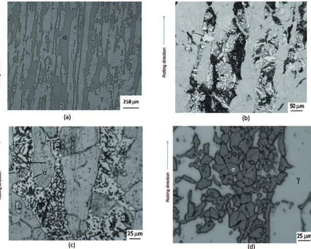
Figure 1a shows AR micrograph. The ferrite (α) content is 47% ± 3% and austenite (γ) content is 53% ± 4%, balanced
as expected. After HT sigma phase begins to nuclear and grow as shown in Figure 1b.
Increasing heat treatment time and temperature, the morphology of the phases obtained are presented in Figures 1c and 1d. The reaction should be eutectoid, α → σ + γ2 as already found by other authors 4,5,7,8.
Figures 1a to 1d shows that all ferrite was consumed. This process occurred at all temperatures, only faster at 800ºC.
In fact, magnetic measured were carried out to conirm the existence of ferrite (using feritscope). It was conirmed that
Table 1: Chemical Composition of UNS S32750 (wt.(%))
C Si Mn P S Cr Ni Mo N Cu
Figure 1: (a) AR Micrograph. Ferrite (α) and austenite (γ). Beraha etching. (b) Micrograph SDSS: Aged 0.5h at 800°C. Showing ferrite
(α), austenite (γ) and σ. Beraha etching. (c) Micrograph SDSS: Aged 50h at 750ºC. Showing austenite (γ), sigma phase (σ) and secondary austenite (γ2). Beraha etching. (d) Micrograph SDSS: Aged 50h at 800ºC. Showing austenite (γ) and sigma phase (σ). Electrolytic etching
at the initial heat treatment times (about 7.5h) the ferrite transforms into sigma and further the remaining ferrite transforms into secondary austenite and sigma. Therefore
the magnetic measurements conirmed that the ferrite
disappeared for the longer heat treatment times, which is shown in Figures 1c and 1d. Analyzing Vickers hardness in the samples, as shown in Figure 2, it is noted that the
hardness in earlier times at 700°C and 750°C are below the
value of the HV in AR sample. This can be explained by the coarsening that occurs in austenite, where the average
austenite spacing increased of 24 μm (AR) to 44 μm (aged 0.5h at 700°C) and 31 μm (aged 0.5h at 750ºC) but the same was not seen in the sample aged at 800°C. For illustration efect is shown the micrograph of the sample aged at 700°C
for 0.5h, Figure 3, where it is noted the thinning of ferrite in comparison to AR sample, shown in Figure 1a. This gives an indication of increased austenite spacing via thermal
treatment in the irst heat treatment times which caused a
decrease in hardness, as shown in Figure 2. From the time of appearance and growth of sigma phase at temperatures of
700 and 750°C, from 3.5h, hardness increases and follows
Figure 2: Vickers Hardness at 700ºC, 750ºC and 800ºC. The dashed line represents the hardness of the AR sample. The errors measured
in the samples heat treated at 800°C are smaller than the symbol
used in Figure and not are shown (used load 200 gram-force).
the trend of the samples heat treated at 800°C. At 800ºC like
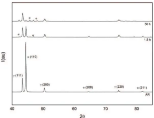
The veriication of the phases present was also performed
via XRD, and is shown in Figures 4, 5 and 6 to 700ºC, 750ºC
and 800ºC. The difracted planes sigma phase are: (410);
(420); (411) and (331) respectively. The XRD technique has the limitation of detecting small amounts in volume of phases. In this work the XRD technique detects the presence
of sigma phase only after 7.5h at 700°C, unlike obtained
via OM, that 2/3.5h at 700ºC which it is possible to note the presence of sigma phase. But qualitatively via XRD, it can be observed a reduction peak ferrite and the appearance and
increase of the peak of sigma phase in all difractograms.
It is interesting to note that with increasing temperature the peaks related to sigma phase appear more quickly. The initial heat treatment times, around 0.5h at 800ºC, there is already
a considerable amount of sigma phase formed, conirming that the kinetics of formation of this phase at 800°C is faster in comparison to 700°C and 750ºC.
Figure 3: Micrograph SDSS: Aged 0.5h at 700ºC. Showing thinning of ferrite in comparison to AR sample, shown in Figure 1a. Beraha etching.
Figure 4: X-Ray difraction patterns at 700ºC. AR, aged 7.5h and 50h.
Figure 5: X-Ray difraction patterns at 750ºC. AR, aged for 1.5h and 50h.
Figure 6: X-Ray difraction patterns at 800ºC. AR, aged for 0.5h and 50h.
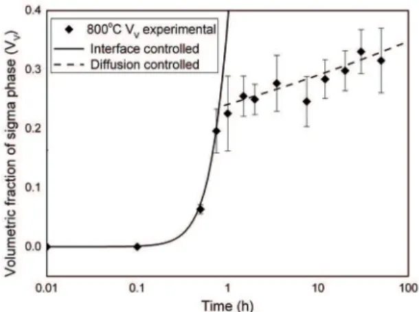
The kinetics of transformation was studied by JMAK equations, and the microstructural partial path (MP) SV
versus VV and <λ> versus VV. Figures 7, 8 and 9 show VV as a function of time to 700ºC, 750ºC and 800ºC, respectively.
The experimental data were itted to Eq.1 together with Eq.2.
Analyzing Figures 7 to 9, it is clear change mechanism in the nucleation and growth of sigma phase. The mechanism 1 (interface controlled growth) is the equation JMAK combining
Eq.1 and Eq. 2, with n approximately equal to 2.7, and
activation energy, Q = 421 kJ / mol for all temperatures. Well the value of n = 2.7 is very close to 3, which indicates site saturation24,25 and the process is controlled by the interface,
which is also clear from the found value of Q (421 kJ/mol)
bigger than Q for Cr-difusion in grain-boundary in α-Fe
(218 kJ/mol)26 and Q for Mo difusion in ferrite (≅289 kJ/
mol)2,27. With 3.2h at 700°C, 1.4 h at 750°C and 0.8h at 800°C,
Figure 7: Volumetric fraction of sigma phase (VV) against time data of specimens aged at 700ºC. The solid line represents mechanism 1 (interface controlled growth) and dashed line represents mechanism
2 (difusion controlled growth).
Figure 8: Volumetric fraction of sigma phase (VV) against time data of specimens aged at 750ºC. The solid line represents mechanism 1(interface controlled growth) and dashed line represents mechanism
2 (difusion controlled growth).
Figure 9: Volumetric fraction of sigma phase (VV) against time data of specimens aged at 800ºC. The solid line represents mechanism 1 (interface controlled growth) and dashed line represents mechanism
2 (difusion controlled growth).
and Eq. 2, with n <1 and activation energy, Q = 165 kJ/mol
for all temperatures. In this case, as the shift mechanism in the aforementioned times, indicate that the process, in the
mechanism 2, is difusion controlled, and in this case, most likely by difusion of chromium. The slope change in JMAK
curves has been found by other authors8. The main problem
of analyzing by JMAK, about the nucleation mode, that is, only by VV in practice, as shown here are deviations of the assumptions from the model. Therefore, MP formulation by SV e <λ> helps to respond on the nucleation mode. The discussion
addressed in the manuscript is focused on two theories: The JMAK and complementarily the microstructural path (MP). The MP formulation was applied to demonstrate the nucleation mode. Thus, by applying both theories we could discuss the kinetics and their nucleation in a complementary fashion. Indeed, the results showed dispersions for both mechanism, but the general trend is clear. This paper proposed to explain using two kinetics equations based on two nucleation control
(interface controlled growth and difusion controlled growth).
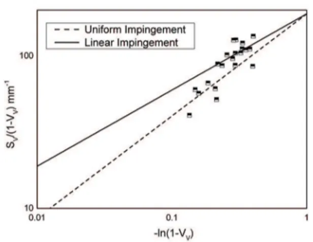
Figure 10 shows the data as SV/(1-VV) versus -ln (1-VV) for the studied temperatures. Two lines are plotted in each
igure. One represents Eq.3 with q = 0.667, which means
site-saturation with uniform impingement and other line
represents Eq.3 with q = 0.5, which means linear impingement.
Indeed, examining Figure 10, it is seen that the data initially adjust the site saturation with impingement uniform but late times the change occurs for linear impingement, in
accordance with shown in Figures 7 to 9, with diference in
this case not only indicates a change in the mechanism, but indicates the location of impingement, which would be in the grain edges. Therefore sigma phase nucleates on edges. In this case, the edges of ferrite/austenite and ferrite/ferrite.
This result suggests that MP using <λ>, Eq.4, would
give p = 1/6. In order to test this suggestion, Figure 11
shows <λ>/(VV)
1/3 versus –ln(1-V
V). Data are itted with
Eq.4 considering linear impingement (p = 1/6) and uniform
impingement (p = 0). Analysis of Figure 11 suggests a transition of random nucleation (p = 0) for the case of linear impingement (p = 1/6). Therefore, the microstructural path theory gave additional and more precise information to complete assessment of the sigma phase transformation on the SDSS used in these experiments.
5. Conclusion
The mechanism formation, kinetics and microstructural path of sigma phase in a UNS S32750 superduplex stainless steel were studied. Based on the results of samples undergoing
isothermal aging at temperatures 700ºC, 750ºC and 800°C,
the main conclusions were:
Figure 10: MP, SV in function of the VV, with Uniform Impingement and Linear Impingement for SDSS undergoing aging in the temperature range 700ºC-800ºC.
Figure 11: MP, <λ> in function of the VV, with Uniform Impingement and Linear Impingement for SDSS undergoing aging in the temperature range 700ºC-800ºC.
was 18% higher than in the AR sample. At 700ºC
and 750°C, in earlier times of heat treatment, the
austenite grows, so the hardness decreases compared the AR sample. At 700ºC and 750ºC, aged from 3.5h, the hardness increases with the increase of sigma phase and follows the trend of the samples aged at 800ºC.
• By applying the traditional JMAK equation, we can see a shift mechanism in the nucleation and growth of the sigma phase in temperatures studied. Site saturation occurs in the samples and initially
control is by interface. With 3.2h at 700°C, 1.4h at 750°C and 0.8h at 800°C, the change occurs and control is by difusion. Probably the difusion of
Cr in Ferrite.
• For the irst time is applied the microstructural partial path, in study of sigma phase precipitation in superduplex stainless steel. And the method either by SV or <λ> indicates that the nucleation is
site-satured with anisotropic linear impingement. This means that sigma phase nucleates on edges. In this case, the edges of ferrite/austenite and ferrite/ferrite.
6. Acknowledgments
This work was supported by Conselho Nacional de
Desenvolvimento Cientıico e Tecnológico, CNPq, Coordenação de Aperfeiçoamento de Pessoal de Nível Superior, CAPES, and Fundação de Amparo a Pesquisa do Estado do Rio de Janeiro, FAPERJ.
7. References
1. Escriba DM, Materna-Morris E, Plaut RL, Padilha AF. Chi-phase
precipitation in a duplex stainless steel. Materials Characterization. 2009;60(11):1214-1219. doi: 10.1016/j.matchar.2009.04.013
2. Magnabosco R. Kinetics of sigma phase formation in a Duplex Stainless Steel. Materials Research. 2009;12(3):321-327. http:// dx.doi.org/10.1590/S1516-14392009000300012
3. Calliari I, Zanesco M, Ramous E. Inluence of isothermal aging
on secondary phases precipitation and toughness of a duplex stainless steel SAF 2205. Journal of Materials Science. 2006;41(22):7643-7649. doi: 10.1007/s10853-006-0857-2
4. Dobranszky J, Szabo PJ, Berecz T, Hrotko V, Portko M. Energy-dispersive spectroscopy and electron backscatter difraction
analysis of isothermally aged SAF 2507 type superduplex stainless steel. Spectrochimica Acta Part B: Atomic Spectroscopy. 2004;59(10-11):1781-1788. doi: 10.1016/j.sab.2004.07.010
5. Hsieh CC, Wu W. Overview of Intermetallic Sigma (σ) Phase
Precipitation in Stainless Steels. International Scholarly
Research Network Metallurgy. 2012;2012:732471. doi:
10.5402/2012/732471
6. Kobayashi DY, Wolynec S. Evaluation of the low corrosion
resistant phase formed during the sigma phase precipitation in duplex stainless steels. Materials Research. 1999;2(4):239-247. http://dx.doi.org/10.1590/S1516-14391999000400002
7. Villanueva DME, Junior FCP, Plaut RL, Padilha AF. Comparative
study on sigma phase precipitation of three types of stainless steels: austenitic, superferritic and duplex. Materials Science and Technology. 2006;22(9):1098-1104. doi: 10.1179/174328406X109230
8. Elmer JW, Palmer TA, Specht ED. Direct Observations of
Sigma Phase Formation in Duplex Stainless Steels Using
In-Situ Synchrotron X-Ray Difraction. Metallurgical and
Materials Transactions A. 2007;38(3):464-475. doi: 10.1007/
s11661-006-9076-3
9. Badji R, Bouabdallah M, Bacroix B, Kahloun C, Belkessa B, Maza H. Phase transformation and mechanical behavior in annealed 2205 duplex stainless steel welds. Materials Characterization. 2008;59(4):447-453. doi: 10.1016/j.matchar.2007.03.004
10. Fan K, Liu F, Ma YZ, Yang GC, Zhou YH. Modeling of
σ-phase precipitation in a 2205 duplex stainless steel using an
analytical soft impingement treatment. Materials Science and
Engineering: A. 2010;527(18-19):4450-4553. doi: 10.1016/j.
11. Johnson WA, Mehl RF. Reaction kinetics in processes of nucleation and growth. Transactions of the American Institute
of Mining and Metallurgical Engineers. 1939;135:416-441.
12. Avrami M. Kinetics of phase change. I General theory. The
Journal of Chemical Physics. 1939;7(12):1103-1112. http://
dx.doi.org/10.1063/1.1750380
13. Avrami M. Kinetics of phase change. II Transformation-time relations for random distribution of nuclei. TheJournal of Chemical Physics. 1940;8(2):212-224. http://dx.doi.org/10.1063/1.1750631
14. Avrami M. Granulation, phase change, and microstructure kinetics of phase change. III. TheJournal of Chemical Physics. 1941;9(2):177-184. http://dx.doi.org/10.1063/1.1750872
15. Kolmogorov AN. The statistics of crystal growth in metals.
Isvestiia Academii Nauk SSSR - Seriia Matematicheskaia.
1937;1:333-359.
16. Gokhale AM, Dehof RT. Estimation of nucleation rate and growth
rate from time dependence of global microstructural properties during phase transformations. Metallurgical Transactions A. 1985;16(4):559-564. doi: 10.1007/BF02814229
17. Vandermeer RA, Rath BB. Modeling recrystallization kinetics in a deformed iron single crystal. Metallurgical Transactions A. 1989;20(3):391-401. doi: 10.1007/BF02653918
18. Vandermeer RA, Masumura RA. The microstructural path of grain-boundary-nucleated phase transformations. Acta Metallurgica et Materialia. 1992;40(4):877-886. doi:10.1016/0956-7151(92)90031-9
19. Vandermeer RA, Jensen DJ. The Migration of High Angle Grain Boundaries During Recrystallization. Interface Science. 1998;6(1):95-104. doi: 10.1023/A:1008668604733
20. Vandermeer RA, Jensen DJ. Microstructural path and temperature dependence of recrystallization in commercial aluminum. Acta Materialia. 2001;49(11):2083-2094. doi: 10.1016/S1359-6454(01)00074-X
21. Vandermeer RA. Microstructural descriptors and the efects of
nuclei clustering on recrystallization path kinetics. Acta Materialia. 2005;53(5):1449-1457. doi: 10.1016/j.actamat.2004.10.054
22. Sieurin H, Sandström R. Sigma phase precipitation in duplex stainless steel 2205. Materials Science and Engineering: A. 2007;444(1-2):271-276. doi: 10.1016/j.msea.2006.08.107
23. Russ JC, Dehof RT. Practical stereology. 2nd ed. New York:
Kluwer Academic/Plenum Publishers; 2000. p. 45-78.
24. Christian JW. The theory of transformations in metals and alloys: Part I. 3rd ed. Oxford: Elsevier; 2002.
25. Rios PR, Padilha AF. Microstructural path of recrystallization in a commercial Al-Mn-Fe-Si (AA3003) alloy. Materials
Research. 2003;6(4):605-613.
http://dx.doi.org/10.1590/S1516-14392003000400030
26. Wang ZB, Tao NR, Tong WP, Lu J, Lu K. Difusion of chromium
in nanocrystalline iron produced by means of surface mechanical attrition treatment. Acta Materialia. 2003;51(14):4319-4329. doi: 10.1016/S1359-6454(03)00260-X
27. Nitta H, Miura K, Iijima Y. Self-difusion in iron-based Fe–Mo