A RUNTIME STABILITY ANALYSIS OF CLOCK SYNCHRONIZATION
PRECISION ON A TIME-TRIGGERED BUS PROTOTYPE
Fabiano C. Carvalho
∗ [email protected]Carlos E. Pereira
† [email protected]∗Mectron Engenharia, Indústria e Comércio S.A.
Av. Brigadeiro Faria Lima, 1399 São José dos Campos - Brazil contact: [email protected]
†Department of Electrical Engineering
Federal University of Rio Grande do Sul Porto Alegre - Brazil
contact: [email protected]
ABSTRACT
This paper provides a runtime stability analysis of the Daisy-Chain clock synchronization algorithm running over CASCA – a time-triggered extension of CAN bus. The main objective is to show with practical results how to achieve global time base of high precision and how this precision is affected by the modification of the TDMA transmission schedule. That contributes by providing some basic guidelines for the task of designing time-triggered, TDMA-based distributed systems for embedded control applications.
KEYWORDS: Time-Triggered Systems, Clock Synchroniza-tion, Rapid Prototyping
RESUMO
Este artigo apresenta uma análise de estabilidade do algo-ritmo de sincronização de relógios Daisy-Chain sendo execu-tado sobre a plataforma CASA - um sistema de comunicação baseado no CAN bus. O objetivo é mostrar como estabelecer e manter uma base de tempo global de alta precisão. Mais ainda, o trabalho mostra a partir de resultados práticos como
Artigo submetido em 31/01/2007 (Id:778) Revisado em 10/09/2008 e em 01/12/2008
Aceito sob recomendação do Editor Associado Prof. José Reinaldo Silva
esta precisão é afetada pela modificação do padrão de comu-nicação TDMA. Pretende-se que este trabalho possa contri-buir para o projeto de sistemas distribuidos baseados em uma arquitetura de comunicação do tipo time-triggered.
PALAVRAS-CHAVE: Sistemas Time-Triggered, Sincroniza-ção de Relógios, PrototipaSincroniza-ção Rápida
1
INTRODUCTION
Time-triggered buses are becoming a cost-effective solution for the design of safety-critical distributed systems. Ex-amples are the FlexRay protocol, the TTCAN, the Time-Triggered Protocol and the DACAPO platform. Detailed information about each bus can be found respectively in (FlexRay, 2004), (Hartwich et al., 2002), (TTP/C, 2003), and (Rostamzadeh et al., 1995). All these buses perform essen-tially distributed clock synchronization by applying differ-ent mechanisms. Nevertheless, performance characteristics of these platforms are usually provided in terms of transmis-sion speed and bus arbitration latencies but either none or very poor information is given about the stability of the clock synchronization service. In (FlexRay, 2004), for instance, it is suggested to consider a worst case precision of11.7µsfor a FlexRay bus which is calculated by using empirical equa-tions. On the other hand, the TTP/C document claims a clock precision of1µsbut only for very stable and adequate oper-ating conditions. An interesting theoretics stability analysis of the TTP/C clock synchronization mechanism is presented in (Nemeth, 2003). In this paper the authors provide mathe-matical models to help improving global time precision but physical effects like oscillators drift and message transmis-sion delays are not considered. The TTCAN has a central-ized time reference so it is relatively simple to derive clock stability analysis as shown in (Hartwich et al., 2002). Un-fortunately, TTCAN suffers from lack of reliability as global time relies on a single master node which may be replicated. Replication of the TTCAN master introduces complexity and moves part of the problem to the application level. For the DACAPO platform no information on clock synchronization stability was found.
In systems with essentially distributed time base the quality of clock synchronization primitive depends on many factors, most of them related to physical characteristics like crystal oscillator drifts, bus latencies, and so on. The impact of these physical factors is difficult to predict so an experimental anal-ysis becomes important. Another issue comes from design choices. Even though it may not be evident, it is relatively simple to show that the definition of the TDMA schedule also affects the behavior of the clock synchronization service. In this paper we investigate the impact on global time precision resulting from the modification of the TDMA transmission pattern of a distributed system prototype. The CASCA plat-form – a time-triggered extension of the native CAN bus – was used as the underlying communication architecture.
This paper is structured as follows. Section 2 reviews main concepts of clock synchronization theory applied to TDMA systems. The CASCA platform is briefly described in section 3. The runtime stability analysis is presented in section 4. Section 5 closes this paper with some concluding remarks.
2
CLOCK SYNCHRONIZATION
The theory of clock synchronization in distributed systems is vaste and has been exhausted in the literature over the last years. For a more deep discussion in this subject the reader is referred to (Lamport and Melliar-Smith, 1985), (Srikanth and Toueg, 1987), (Ramanathan et al., 1990) and (Schneider, 1986). In this section, only the fundamental prin-ciples applicable to TDMA-based systems are reviewed and basic notation is provided.
Roughly speaking, clock synchronization is a distributed function whose objective is to guarantee that the difference between local time bases of distinct nodes do never exceed an upper limit. This upper limit is called the precision of the synchronized system, denoted byδmax, and it is commonly
defined by the following formula:
δmax≥ |Cp(t)−Cq(t)| ∀t (1)
in which Cp(t) and Cq(t) are clock readings of any two
nodespandq, andtrefers to physical time.
The precision establishes a theoretical limitation on the gran-ularity of the global time base. In practice, this limitation is never attained due to certain non-deterministic aspects re-lated to the clock reading mechanism that are also addressed in this paper.
Another relevant definition is accuracy. It is used to provide a quantitative representation of how close the logical time base (local or distributed) is to an absolute time reference. Accuracy can be defined as:
γ≥ |C(t)−t| ∀t (2)
in whichC(t)refers to system clock andtrefers to an abso-lute time reference. Clock accuracy is a secondary require-ments since it is not essential to maintain synchronization over a single communication bus. This issue is not addressed in this work.
reading is performed the impact ofρis proportional to2ρR.
Considering that, at runtime, critical control applications may use the global time feature then the clock synchro-nization primitive shall be at least as reliable as the func-tion it supports. In view of that, agreement algorithms are used to minimize the effects of potential erroneous clock readings. The TTP/C bus adopts the Fault-Tolerant Aver-age (FTA) algorithm described in (Kopetz and Ochsenre-iter, 1987) while in FlexRay clock synchronization applies the Fault-Tolerant Midpoint algorithm (FTM) described in (Welch and Lynch, 1988). In both cases clock alignment is proved assuming that there is a minimal number of non-faulty readings in the set of most recent clock samples.
On the other hand, both DACAPO and CASCA platforms use the Daisy-Chain Fault-Tolerant method presented in (Lonn, 1999). The primal difference between the Daisy-chain method and the previous ones is that there is no need to temporarily store clock readings during normal operation. Instead of using a set of readings to calculate a new time reference every node adjusts its local clock according to the time view of the current transmitter. At each clock reading this information is immediately used and then discarded. In the Daisy-Chain method the upper limit on the precision is formally proved in (Lonn, 1999) by assuming that the num-ber of faulty readings per unit of time is less than a predefined rate.
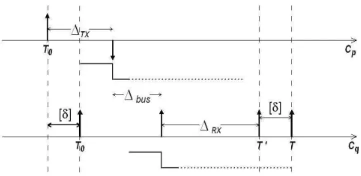
The clock reading procedure implemented in TDMA buses is based on the fact that all relevant information is known a priori from the definition of the global schedule which de-fines what and when actions must be triggered by the sys-tem. Because of that, clock samples can be inferred rather than explicitly sent inside messages. At the moment a node perceives the frame initial pattern it takes a sample of its own clock and compare it with the time it was expecting this transmission to occur. The expecting arrival time is taken directly from the global schedule and matched against the actual arrival time resulting in what is called adeviation, or askew, which is a good estimative of the amount of time the receiver’s local clock is advanced (or late) with respect to the transmitter’s.
Figure 1 shows the implicit reading mechanism implemented in CASCA. The same principle is used in FlexRay and TTP/C. At the sender side when local clockCp reachesT0 an interrupt triggers the transmission of a message. The net-work adapter takes∆T X time units to handle this interrupt
and then the first bit of the message is sent through the phys-ical channel. The electrphys-ical signal takes∆bus time units to
propagate from the sender to the receiver. When the signal arrives at destination, another interrupt triggers a routine that takes a timestamp of the receiver local clock. From the
mo-Figure 1: Clock Reading Mechanism
ment this interrupt rises to the moment the timestamp is actu-ally taken∆RXtime units have been elapsed during interrupt
handling routine execution.
LetCq = T′ be the timestamp taken at the receiver side,
and[δ]1
the skew between local clocks of a sender-receiver pair. The clock synchronization mechanism is interested in the value of[δ]which can be either positive or negative. Be-cause[δ]is not explicitly available for using it may be in-ferred fromCq. From figure 1 we derive the equations used
in the indirect reading mechanism.
First of all, we have that:
T′=T0+ ∆T X+ ∆RX+ ∆bus+ [δ] (3)
The value ofT0, called the senderaction time, is know from the TDMA schedule so, if a good estimation of network de-lays is available then it is possible to infer the clock skew.
It is clear that the accuracy of the clock reading procedure is strongly affected by∆bus,∆T X and∆RX. The bus
de-lay∆busis intrinsic to physical properties like temperature,
bus length and cable material so the variation of this term is difficult to predict. On the other hand,∆T X and∆RX
de-pends on protocol latencies. Even if it is not possible to make these parameters absolutely deterministic the fixed part can be decoupled from the varying part like follows:
∆T X+ ∆RX+ ∆bus=k+ǫ (4)
in whichκ– the fixed part – is calledcompensation term
and ǫ – the varying part – is called the reading error. Hereby, equation 3 can be rewritten in the form:
T′=T0+k+ǫ+ [δ] (5)
In CASCA, the value ofkwas precisely determined by sim-ulation at clock cycle level. It is not a function of time but a static configuration parameter derived from platform spe-cific implementation details. The definition of this parame-ters makes it possible to drastically reduce the reading error by compensating deterministic delays.
We also define theexpected arrival time, denoted simply byT, as a reference value for the timestamp which considers zero skew:
T =T0+k (6)
so the value of[δ]can be inferred by subtracting the actual timestamp from the the expected arrival time as follows:
T−T′= [δ] +ǫ (7)
Because ofǫthe differenceT −T′ is not the exact
devia-tion ofpandqclocks but a good estimation. In practice the reading error cannot be neglected but it can be restricted to very small bounds by decoupling the varying part from the fixed part. The value ofǫis minimized by making protocol latency variances as small as possible. For that purpose it is suggested to avoid the introduction of hubs and repeaters, and any other device in the signal path that may generate un-predictable delays.
3
PLATFORM DESCRIPTION
A simplistic scheme of the proposed communication plat-form is shown in figure 2. It has been designed as an ex-tension of the original CAN bus specified in (CAN, 1999). The CAN bus provides physical and data link layers while the time-triggered extended layer includes advanced runtime services such as clock synchronization and TDMA arbitra-tion.
Figure 2: Proposed Communication Platform
Figure 3: TDMA Arbitration
Once initialized, the network adapters operate autonomously. Messages are transmitted and received following a prede-fined global TDMA schedule that cannot be disturbed by timing behavior of host applications. The contents of each message – e.g. control variables and sensor samples – are exchanged between the host and the network adapter through an interface memory implemented using dual-port static memories (SRAM).
The CASCA adapter core was implemented in VHDL and C code. It can be used free of charge for non-commercial purposes. For more detailed design information the reader is referred to (Carvalho et al., 2006a) and (Carvalho et al., 2006b).
Figure 3 shows a scope image captured during stable oper-ation of an elementary distributed system configured with a 3-slot, single-round TDMA network cycle. The transmission signal of each node (TX 1, 2 and 3) has been captured in or-der to achieve a better visualization of message exchanging.
The clock synchronization primitive implemented inside the network adapter ensure global time alignment by applying the Daisy-Chain method. Thanks to that, there is no need to rely on a specific node for the global time base to be pre-served. It requires that at least two nodes remain active to ensure a bounded upper limit forδmax. The principle of
op-eration of the Daisy-Chain Algorithm is relatively simple. The network can be viewed as a logical cascade of nodes alternating the role of time leader in a repetitive sequence. The leadership order is off-line defined and coincides with the TDMA transmission order.
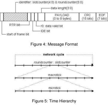
CASCA messages conform with standard CAN message for-mat as shown in figure 4. Application data is allocated in the payload field for transmission. In addition, the identifier field is filled with TDMA control information that is necessary for the startup mechanism and integration of new nodes. Ther0
Figure 4: Message Format
Figure 5: Time Hierarchy
whenever the payload field carries unuseful or non-updated sensor data.
Time management relies on a hierarchy of counters as indi-cated in figure 5. At the lowest level is microtick counter which is updated directly from the primary time source, for instance, a crystal oscillator. The size of the microtick time unit may differ from one node to another if oscillator fre-quencies are not equal.
At the second level is the macrotick counter which is up-dated whenever the microtick counter overflows. This is the only counter that is subject to corrections and its size of the macrotick must be the same for all nodes. The macrotick level defines the global time granularity.
The upper level corresponds to the system cycle counter which keeps track of the TDMA network cycle. For con-venience, this counter is subdivided in round and slot coun-ters. In CASCA, the largest network cycle that is possible to configure has 64 rounds with 32 slots each one. Being the number of slots per TDMA round a constant, the cycle counter can be expressed in the form:
[cyclecounter]=[roundcounter:slotcounter]
By adding the minimum unit of global time – the macrotick – we have a formal representation of the global time base:
[roundcounter:slotcounter:macrotick]
This is a logical representation of the triggerable time hori-zon over which all communication activity of the distributed
system is mapped. It makes possible to globally quantify temporal parameters like periodicity, delays, release times, and so on.
Clock synchrony in CASCA is based on phase correction, that is, the macrotick counter is suddenly modified by adding or subtracting a number of microticks. The number of mi-croticks to be added or subtracted corresponds to the correc-tion term, denoted byΛ, which is calculated from the most recent clock reading as follows:
Λ =δ·2−L
In which the value ofLdepends on the size ofδ. LetMbe the size of the macrotick unit soLis determined according to table 1:
Table 1: [Correction term calculation criteria]
0≤ |δ|<14M L←0
1
4M≤ |δ|< 1
2M L←1 1
2M≤ |δ|<M L←2
|δ| ≥M L← ∞
The above criteria of correction term calculation prevents from large clock corrections which may lead to instabil-ity during the startup procedure. The reader is referred to (Lonn, 1999) for more information.
By using this very simple technique it is possible to maintain distributed clock alignment even if there are only two nodes communicating.
4
RUNTIME STABILITY ANALYSIS
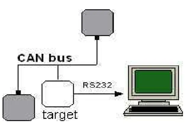
The prototype setup used during runtime analysis consists in three Xilinx Spartan2E FPGA devices equipped with CAN transceiver ICs. Two nodes are connected to the extremities in order to facilitated bus termination while the third node is connected at the middle of the cable as indicated in figure 6.
There is no application layer since host processors were not included. The platform operates autonomously sending mes-sages with no useful information inside the payload. How-ever, at each transmission the message identifier is filled with protocol information that is necessary for TDMA operation and startup procedure. Timing configuration parameters are summarized in table 2.
In the central node an UART2 was synthesized inside the
Table 2: [Timing configuration parameters]
crystal frequency: 50Mhz microtick size: 20ns
macrotick size: 100 microticks = 2µs slot size: 200 macroticks = 400µs
VHDL entity responsible for counting time. That node con-taining the UART is called target. This makes it possible to capture clock readings from the target into a desktop ma-chine through a RS232 interface. Thousands of samples are collected at each prototype run in order to observe the behav-ior of maximum skew over time as the TDMA transmission pattern is changed.
Stability analysis is performed as shown in figure 7. The tar-get node always transmits in slot 0 since the beginning of each prototype run. There can be one or twostepping nodes
which may change the transmitting slot at runtime in order to modifyRmax, that is, the maximum resynchronization
inter-val. It is worthy to mention that this procedure does not affect the message transmission period. Finally, asRmaxincreases
its effect is checked against the resulting worst case skew. The stability analysis procedure was divided in 2 phases: enlarged round analysis phase and reduced round analysis phase. Each phase consists in 2 prototype runs as presented next. For each prototype run results are provided by plotting over time the skew samples collected from the target node.
4.1
Enlarged round analysis
1. Configuration: 1 round – 32 slots – 2 active nodes:
System is initialized with the target node assigned to slot 0 and one stepping node assigned to slot 16. As time progresses the stepping node jumps to slot 8 and than to slot 1. That forcedRmax to change from 16
Figure 6: CASCA prototype.
Figure 7: Node Stepping
slots (6.4ms) to 24 slots (9.6ms), and finally to 31 slots (12.4ms). Results are shown in figure 8(a) that indicates the moment the round is reconfigured. One can observe that initially the absolute worst case skew (the distance from the zero) is near 80 microticks then it deteriorates to 90 microticks whenRmaxis increased.
2. Configuration: 1 round – 32 slots – 3 active nodes: System is initialized with the target node assigned to slot 0 and two stepping nodes assigned to slots 10 and 22. As time progresses the stepping nodes jumps to slots 0 and 1. That forced Rmax to change from 12
slots (4.8ms) to 30 slots (12ms). Results are shown in figure 8(b). The initial absolute worst case skew is 55 microticks but whenRmaxis augmented it deteriorates
to 65 microticks.
4.2
Reduced round analysis
1. Configuration: 1 round – 12 slots – 3 active nodes:
System is initialized with stepping nodes in slots 4 and 8 and then they jump to slots 1 and 2. The value ofRmax
thus changes from 4 slots (1.6ms) to 10 slots (4ms). Re-sults are shown in figure 9(a). The initial absolute worst case skew is 20 microticks (0.4µs) but whenRmax is
augmented it deteriorates to 30 microticks (1.2µs).
2. Configuration: 1 round – 3 slots – 3 active nodes: In this case the stepping nodes are assigned to slots 1 and 2 up to the end of the prototype run. Results pro-vided in figure 9(b) represents the maximum precision attainable by this prototype.
(a) Configuration: 1 round – 32 slots – 2 active nodes (b) Configuration: 1 round – 32 slots – 3 active nodes
Figure 8: Practical results – enlarged TDMA round analysis
(a) Configuration: 1 round – 12 slots – 3 active nodes (b) Configuration: 1 round – 3 slots – 3 active nodes
Figure 9: Practical results – reduced TDMA round analysis
2 NODES:
Rmax[ms] δmax[µs]
6.4 1.56 9.6 1.66 12.4 1.74
3 NODES:
Rmax[ms] δmax[µs]
0.4 0.36 1.6 0.4
4 1.2
4.8 1.1 12 1.3
Table 3: [Skew analysis]
base precision is directly affected byRmax. In the particular
case when the entire channel bandwidth is used (no empty slots) the maximum resynchronization interval is minimized resulting in a global time base precision of less than 1µs.
5
FINAL REMARKS
This paper presented a runtime stability analysis of a time-triggered communication platform. It was showed that by minimizing the maximum slot interleaving time it is pos-sible to enhance quality of clock synchronization service without changing message transmission periods. Moreover, this paper has presented a very simple clock synchronization method to achieve a global time base precision of less than 1µs for special cases in which the bus inactivity time and hence the resynchronization interval is minimized.
REFERENCES
CAN (1999).CAN Specification 2.0.
E. T. (2006a). A practical implementation of the fault-tolerant daisy-chain clock synchronization algorithm on can,DATE ’06: Proceedings of the conference on Design, automation and test in Europe, pp. 189–194.
Carvalho, F. C., Pereira, C. E., Freitas, E. P. and Silva Jr., E. T. (2006b). A time-triggered controller area network platform with essentially distributed clock synchroniza-tion,Proceedings of the 12th IFAC Symposium on
In-formation Control Problems in Manufacturing.
FlexRay (2004). FlexRay Communications System Protocol Specification Version 2.0, FlexRay Consortium.
Hartwich, F., Müller, B., Fuhrer, T. and Hugel, R. (2002). Timing in the ttcan network,Proceedings 8th
Interna-tional CAN Conference.
Kopetz, H. and Ochsenreiter, W. (1987). Clock synchroniza-tion in distributed real-time systems,IEEE Trans. Com-put.36(8): 933–940.
Lamport, L. and Melliar-Smith, P. M. (1985). Synchronizing Clocks in the Presence of Faults,Journal of the ACM 32(1): 52–78.
Lonn, H. (1999). The fault tolerant daisy chain clock synchronization algorithm,Research report, Chalmers University of Technology.
Nemeth, J. (2003). Stability analysis of distributed clock syn-chronization in the time-triggered architecture, Intelli-gent Signal Processing, 2003 IEEE International
Sym-posium on, pp. 213–218.
Ramanathan, P., Shin, K. G. and Butler, R. W. (1990). Fault-Tolerant Clock Synchronization in Distributed Sys-tems,Computer23(10): 33–42.
Rostamzadeh, B., Lonn, H., SnedsbGl, R. and Torin, J. (1995). DACAPO – A Distributed Computer Architec-ture for Safety-Critical Control Applications,
Proceed-ings of the Intelligent Vehicles Symposium, pp. 376–
381.
Schneider, F. B. (1986). A Paradigm for Reliable Clock Synchronization,Research report, Department of Com-puter Science, Cornell University.
Srikanth, T. K. and Toueg, S. (1987). Optimal clock synchro-nization,J. ACM34(3): 626–645.
TTP/C (2003). Time-Triggered Protocol TTP/C High-Level
Specification Document Protocol Version 1.1, TTA
Group.