BEHAVIOUR OF JOINT COMPONENTS OF I BEAM TO TUBULAR
COLUMNS CONNECTIONS WITH WELDED REVERSE CHANNEL
Luís B. Magalhães*, Carlos S. Rebelo** and Sandra S. Jordão**
* Polytechnic Institute of Castelo Branco, Technical-Scientific Unit of Civil Engineering, Portugal e-mail: [email protected]
** University of Coimbra, Department of Civil Engineering, Portugal
e-mails: [email protected], [email protected]
Keywords: Beam to column joints, tubular columns, reverse channel, nonlinear behaviour, components tests.
Abstract. The main purpose of this investigation is the characterisation of the nonlinear cyclic
behaviour of steel joints between I profile beams to hollow section columns with welded reverse channel. In this paper a comparison is made between experimental tests and numerical finite element model results. In the experimental program the characteristics of the nonlinear behaviour of the principal reverse channel components is assessed by means of bending tests. The numerical models are developed in the software LUSAS and calibrated with the results from the experimental tests. The main focus of these tests will be on the results concerning the main components of the reverse channel detail, i.e. web face in bending, flanges panels in shear, compression and tension, in terms of strength, stiffness and rotation capacity. The parameters which have been varied in the tests are the geometry of the loaded area and the dimensions of the flanges and web of the U shaped element.
1 INTRODUCTION
When compared with other steel shapes, tubular profiles show a privileged structural behaviour due to their ability to withstand axial loads, bending in several directions and torsion, besides considerable advantages in terms of maintenance and aesthetics. The welded reverse channel connection is a good solution since it allows for a bolted joint between I beam to hollow column. Furthermore, this type of joint detail has a reasonable construction cost, is easy to implement and features large ductility through the deformation of the web panel.
The fact that, in the past, tubular shapes haven’t been such an obvious choice is due to the fact that joints between tubular shapes or to tubular shapes are either completely welded or difficult and expensive, because there is no access to the inside of the tubular shape. Due to this fact, a lesser effort has been directed to research on these typologies, and less comprehensive methods of analysis or code formulation exists for their design.
Eurocode 3 [1] provides some rules for welded connections between tubular profiles, but not for bolted connections. However, due to its strategic importance, this topic has had several significant contribution in the last decade. Among those some research initiative from the “Comité International pour le Développement et l’Étude de la Construction Tubulaire” CIDECT stands out, aiming at the development of an unified design approach for steel joints by extending the field of application of the Eurocode 3 component method [2].
2 EXPERIMENTAL INVESTIGATION 2.1 Parametric range
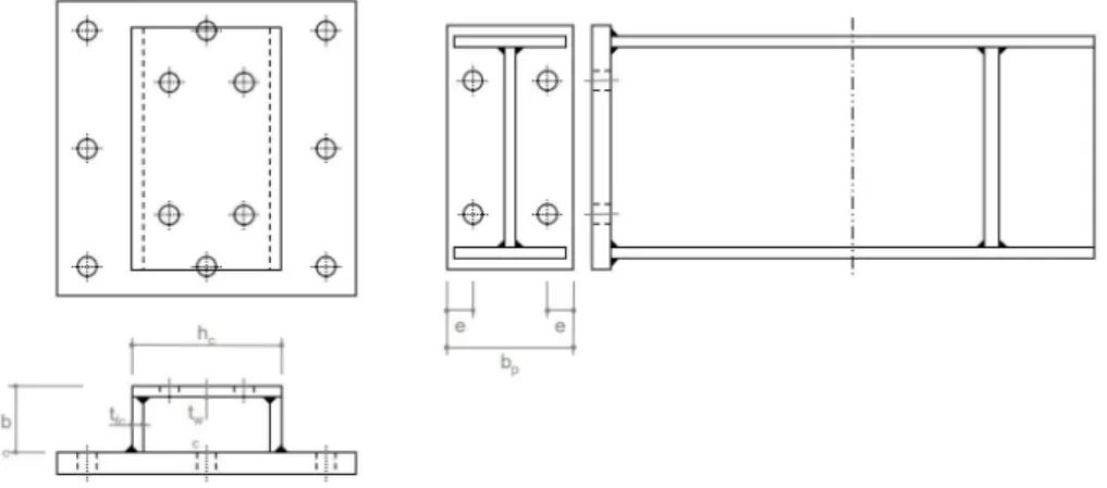
The prototypes are formed by the reverse channel (two flange plates welded to one web plate with holes for bolted to end plate beam). The steel grade is S275. The configurations selected for the experimental tests correspond to a parametric variation on the factors with major influence on the structural behaviour of the reverse channel. These parameters, identified in the schematics of figure 1, are the thicknesses and width of the web and flanges, the distance between bolts in the same row and the geometry of the end plate. The dimensions of the prototypes are listed in table 1.
Figure 1. Schematics for beam and prototype.
Table 1. Prototypes dimensions [mm]. Prototype
Model p2 bc hc twc tfc
Beam end plate
bp e A-11 85 90 200 12 15 155 35 A-12 15 A-13 185 A-14 220 A-15 100 200 170 A-16 80 45 A-17 100 75 35 A-18 10
2.2 Test lay out
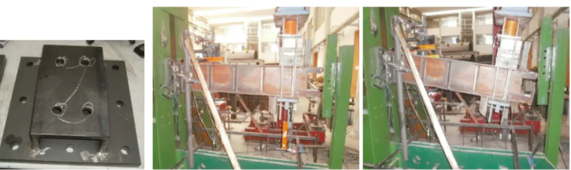
The experimental lay out corresponds to a beam to column connection between an I-beam and a vertical steel rigid structure using a reverse channel element. The figure 2 illustrates the channel and figure 3 the experimental lay out, prior and after the test.
Since the sole purpose is to assess the behavior of the channel prototypes, the others elements are considered with sufficient stiffness so that they can be considered not deformable. The channel itself is welded to a stiff plate, shown in figure 2 (25 mm thickness steel grade S355), which is connected to the rigid structure by eight bolts M24, class 10.9, for an easy assemblage. The beam corresponds to an IPE300, with high resistance to bending [3] when compared with the channel.
Figure 2. Reverse channel. Figure 3. Experimental lay out, prior and after the test.
2.3 Loading and measuring device
The tests were performed with a 100 tf jack, which was connected to the beam tip by means of a hinged device, so that the load applied would remain orthogonal to the beam throughout the whole test. The load applied to the structure was measured by means of load cells fitted between the jack and the beam. Deflectometers were used to measure all of the connection rotation components and to assess displacement at key points throughout the structure. Strain gauges were used to assess the stress state at key points throughout the connection and also to assess the strain in the bolts.
3 FINITE ELEMENTS MODELING
The numerical models represent the real prototypes used in experimental tests, depicted in figure 4. The finite element mesh has a tighter discretization in the channel, on the end plate and in the beam area closest to the connection, allowing for a more coarse mesh in the outlying areas.
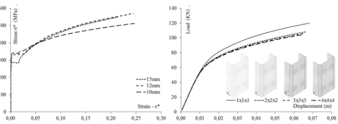
The material is described by means of multilinear curves obtained from uniaxial tension tests on coupons taken from the plates used in experimental tests, for the three thicknesses (10, 12 and 15 mm). True strain and true stress values were calculated from the engineering values obtained from the tests on the material [4], yielding the curves depicted in figure 5.
For the U profile, beam end plate and bolts elements, solid finite elements HX8M and PN6 are used [5]. QTS4 thick shell elements are used for the beam. The modelling of the contact surfaces, between the end plate, the channel web and the bolts, is performed with spring elements JNT4, with high stiffness in compression and very low in tension.
In order to define the optimum mesh discretization a mesh convergence analysis was performed (Top of figure 6). The results, present the bottom of figure 6, show that mesh 2x2x2 is accurate enough.
X Y
Z
Figure 4. Finite elements model.
X Y
Figure 5. Steel stress-strain diagrams. Figure 6. Convergence of finite elements meshes.
4 RESULTS 4.1 Experimental tests
The deformations of the channels in the experimental test are caused by the tension of the bolts at the top, see top pictures of the figure 7, and by beam end plate compression at the bottom, see bottom pictures of the figure 7. In both cases significative plastic deformation are observed.
The prototypes with smaller web thicknesses (A11, figure 7) and wider webs (A14, figure 7) show the higher out of plane bending deformation, as expected. Prototype A-18, the one with the lowest value for flange thickness (10 mm), was the only one who reached rupture at the flange plates.
Figure 7. Deformation on the top and bottom of prototypes A-11 to A-18.
4.2 Numerical models
A nonlinear analysis with automatic increment of the load was performed. Results in terms of deformation and Von Mises stresses are presented in figure 8. The deformation in the numerical models is identical to the one observed in the homologous experimental tests (Figure 8).
5 COMPARISION OF THE RESULTS
Both the results obtained from the experimental tests “EC” and the numerical models “MN” can be expressed in terms of moment-rotation curves. The diagrams and graphics of the figure 9a to figure 6f show in simultaneous the comparison of the “EC” and “MN” results, and the results of parametric study.
In the linear region of moment-rotation curves the behavior of the connections may be expressed in terms of initial stiffness (Sj,ini) and maximum elastic bending moment (Mj) [1]. The post yielding region is characterized by its stiffness (Sj,pl). Table 2 presented these values for experimental and numerical models. The test results show that the thickness and width of the web channel are the parameters that most influence the behavior of the connection. When the web thickness (twc) decreases smaller elastic bending
moments and stiffness are reached (A-12 vs. A-11 results in figure 9a).
Figure 9a. Decrease web channel thickness (twc).
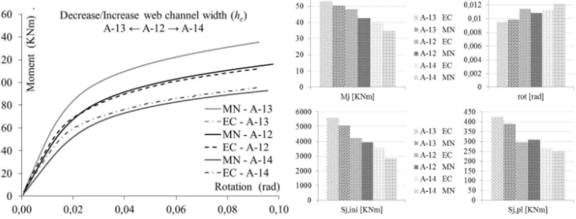
Varying the width of the web (hc), when the same width of beam end plate is considered, leads to
significant variation of stiffness and elastic moment. Increasing hc (A-12 vs. A14 results in figure 9b)
leads to a decrease of these values, because the variation of hc alters the bending stiffness of the channel’s
web. Decreasing hc (A-12 vs. A-13 results in figure 9b) leads to an increase in the stiffness and elastic
bending moment resistance.
Figure 9b. Decrease/Increase web channel width (hc).
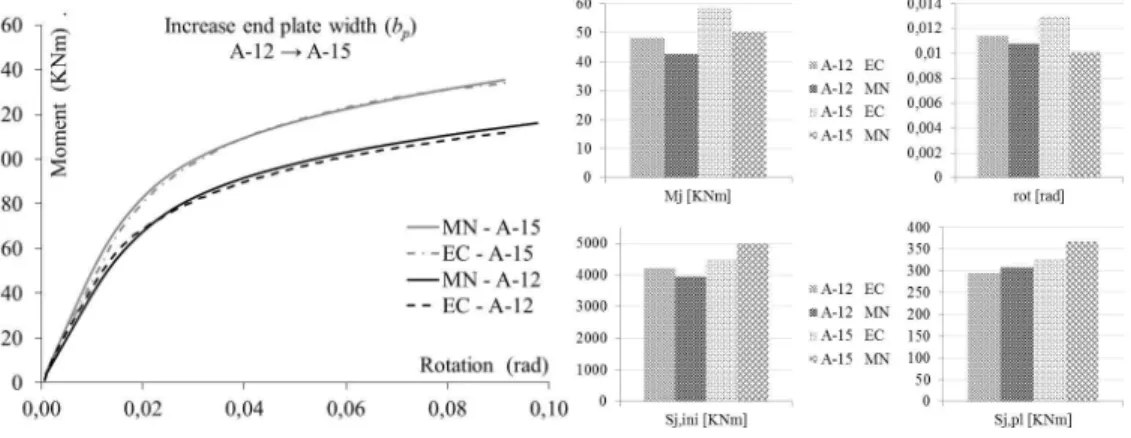
expressed by the beam’s end plate width (bp) in the compression zone, and by the distance between bolts
(p2) in the tension zone. Results show that the larger the endplate is the higher the stiffness and the
resistance are. This is due to the fact that load transfer is more direct to the column flanges and less dependent on bending of column web. Comparison of A-12 and A-13 results in figure 9b, as well as A-12 and A-15 in figure 9c, highlight this trend.
Figure 9c. Increase end plate width (bp).
In tension zone, lower stiffness is achieved when the load is applied closer to the channel flanges (A-15 vs. A-16 results in figure 9d).
Figure 9d. Decrease distance between bolts (p2).
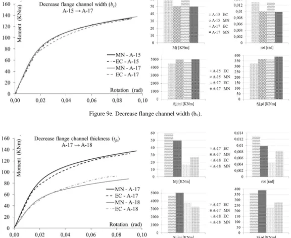
The variation of the flanges width bc does not evidence significant changes in joint behavior. This is
due to the fact that the variation on this parameter is insufficient to change the flanges slenderness. However, the reduction of this parameter increases the stiffness of the joint (A-15 vs. A-17 results in figure 9e).
The influence of flange thickness (tfc) variation is obvious when we compare A-17 vs. A-18 results in
figure 9f. The reduction of tfc alters significantly the joint’s behavior, since decrease flange resistance in
compression and tension.
For the majority of the results present in table 2, a good fit was obtained between the results of the numerical models and the experimental. There are a very good correlation between the curves for the models A-11, A-12, A-15 and A-17, and in the others the correlation is satisfactory. The results of the
parametric variation are summarized in table 3. The comparisons established in this table shows that the tendencies in parametric variations are practically identical in both types of test, finding only one case of conflicting results.
Figure 9e. Decrease flange channel width (bc).
Figure 9f. Decrease flange channel thickness (tfc).
Table 2. Elastic bending moment [KNm], rotation [rad] and stiffness [KNm] of the joints. Prototype Model Mj Rotation Sj,ini Sj,pl EC MN EC MN EC MN EC MN A-11 43,2 34,8 0,0116 0,0105 3724,1 3314,3 274,6 265,9 A-12 48,1 42,6 0,0114 0,0108 4219,3 3944,4 295,3 308,1 A-13 53,1 50,3 0,0095 0,0099 5589,5 5080,8 424,4 389,5 A-14 40,1 34,8 0,0113 0,0122 3548,7 2852,5 262,8 249,7 A-15 58,2 50,3 0,0130 0,0101 4476,9 4980,2 329,0 366,8 A-16 52,8 46,4 0,0095 0,0102 5557,9 4549,0 300,0 298,4 A-17 59,8 49,7 0,0128 0,0099 4671,9 5020,2 362,9 388.9 A-18 17,0 26,8 0,0045 0,0082 3777,8 3268,3 230,1 278,6
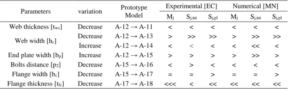
Table 3. Parametric study synthesis. Parameters variation Prototype
Model
Experimental [EC] Numerical [MN] Mj Sj,ini Sj,pl Mj Sj,ini Sj,pl Web thickness [twc] Decrease A-12 → A-11 < < < < < <
Web width [hc]
Decrease A-12 → A-13 > >> >> > >> >> Increase A-12 → A-14 < < < < << < End plate width [bp] Increase A-12 → A-15 > > > > >> > Bolts distance [p2] Decrease A-15 → A-16 < > < < < < Flange width [bc] Decrease A-15 → A-17 = = > = = > Flange thickness [tfc] Decrease A-17 → A-18 <<< < << << << << 6 CONCLUSIONS
The loaded area, the web and flanges thicknesses and widths are parameters with important influence in the structural behavior of reverse channel beam-to-column connections. Significant changes of the structural behavior of the joint were found for the parametric variation considered in the study, confirming it was well tailored for the purpose.
The resistance of the connection is higher when the thickness of the web is greater, but related to the stiffness there aren’t significant differences. This is due to the fact that when we increase the web thickness, the geometric configuration and load transfer paths do not change.
Largest ratios between the widths of the web and end plate imply lowers resistance and stiffness. This is justified because for smaller ratios the compressive force transmitted by the end plate is supported by the flanges in compression, yielding greater resistance and stiffness to the joint, while in the opposite case the resistance and stiffness are conditioned by the web in bending.
The distance between bolts in the tension row is an influential parameter, because the load distribution across the channel width influences the load transfer path from the web to the flanges of the channel, thus influencing also the channel web plastic deformation.
The flanges width and thickness are parameters that influence the behavior of the joint. Due to the fact that the profiles flanges support compression, tension and shear, the variation of its slenderness implies loss of strength and stiffness.
From the comparisons between the numerical model and experimental results, it is concluded that the approximation between the results is good.
REFERENCES
[1] CEN, Eurocode 3, Part 1.8: “Design of Joints”, EN 1993-1-8, 2010.
[2] Jaspat, J, Pietrapertosa, C, Weynand, K, Busse, E, Klinkhammer, R, “Development a Full Consistent Design Approach for Bolted and Welded Joints in Building Frames and Trusses between Steel Members Made of Hollow and/or Open Sections”, Application of the Component Method, Volume 1 - Practical Guidelines, CIDECT Report 5BP-4/05, 2005.
[3] CEN, Eurocode 3, Part 1.1: “General Rules and Rules for Buildings”, EN 1993-1-1, 2010.
[4] RILEM, “Tension Testing of Metallic Structural Materials for Determining Stress-Strain Relations under Monotonic and Uniaxial Tensile Loading”, Draft Recommendations, 23 35-46, 1990. [5] LUSAS, FEA Ltd, “Element Reference Manual”, Version 13, United Kingdom.