Tiago André Rolo Teixeira
Licenciado em Ciências de Engenharia Electrotécnica e de Computadores
Organising Interoperability Information on Highly
Dynamic and Heterogeneous Environments
Dissertação para obtenção do Grau de Mestre em Engenharia Electrotécnica e de Computadores
Orientador : Adolfo Steiger Garção, Professor Catedrático, FCT/UNL
Co-orientador : Pedro Miguel Maló, Professor Assistente, FCT/UNL
Júri:
Presidente: Doutor Tiago Oliveira Machado de Figueiredo Cardoso - FCT/UNL
Arguente: Doutor Manuel Martins Barata - ISEL/IPL
Vogais: Doutor Adolfo Steiger Garção - FCT/UNL Mestre Pedro Miguel Maló - FCT/UNL
iii
Organising Interoperability Information on Highly Dynamic and Heterogeneous En-vironments
Copyright cTiago André Rolo Teixeira, Faculdade de Ciências e Tecnologia, Universidade Nova
de Lisboa
Acknowledgements
Este espaço é dedicado a todos aqueles que me acompanharam durante a elaboração desta tese. Para todos eles, o meu mais sincero obrigado!
Primeiro, gostaria de agradecer a toda a minha família, e em especial aos meus pais e irmão pela compreensão, carinho e muita paciência durante todo este tempo. Ao Telepe, Né e ao meu afilhado Martim, por todas os momentos de descontração e diversão. À Adriana, por toda a amizade, amor, dedicação e por ter estado sempre presente em todos os momentos ao longo da minha formação.
Ao Pedro Maló e ao Bruno Almeida, por me terem possibilitado fazer este trabalho de investi-gação, por me terem orientado na direcção certa, pela objetividade e exigência. Ao meu compan-heiro de tese Márcio Mateus, por todas as horas perdidas a discutir ou divagar, e principalmente pela disponibilidade que sempre demonstrou para contribuir para a conclusão desta dissertação.
À malta do GRIS, Baeta, Casanova, Fábio, Edgar, Raquel, Hugo, e a todos os colegas da FCT, Vitor, Gonçalo, Manta, Catarina, Zé Manel, Marcelo, Edu, Chalaça, Vanessa e David.
Muito obrigado a todos.
Abstract
The “Internet of Things” is a dynamic global network infrastructure where physical and virtual “things” communicate and share information amongst themselves. Plug and Interoperate is an approach that allows heterogeneous “things” to plug (into data) and seamlessly exchange informa-tion within the environment. To allow that, Plug and Interoperate needs to have the comprehension about the existing interoperability information. For this, the interoperability information needs to be duly organised. However, and in the “Internet of Things”, this presents major challenges. First, it is difficult to index all interoperability information due to the “things” heterogeneity (many and different languages and formats) and due to the dynamics of the system (disparate things en-tering/leaving the environment at all times). Also, that the environment can be used with much different purposes, which hinders the way on how the interoperability information should be or-ganised. So, an architecture of an Interoperability Repository System is presented, in order to organise all interoperability information in this kind of environments. The solution handles het-erogeneous interoperability information and allows users to add a User Space to the repository in order to customise it to specific needs. It also provides a notification mechanism in order to notify users of new or updated interoperability information.
Keywords: Internet of Things, Interoperability, Heterogeneity, Repository
Resumo
A “Internet of Things” é uma infraestrutura de rede dinâmica e global, onde “things” físicas e virtuais comunicam e trocam informação entre si. O “Plug and Interoperate” é uma abordagem que permite que “things” heterogéneas se liguem, e troquem informações dentro do ambiente sem problemas. Para o permitir, o “Plug and Interoperate” precisa do conhecimento sobre a informa-ção relativa à interoperabilidade existente. Portanto, é necessário que essa informainforma-ção relativa à interoperabilidade esteja devidamente organizada. No entanto, esta organização apresenta grandes desafios no ambiente da “Internet of Things”. Primeiro, porque é difícil indexar toda a informação relativa à interoperabilidade, devido à heterogeneidade das “things” (muitas e diferentes lingua-gens e formatos) e devido ao dinamismo do sistema (diferentes “things” estão continuamente a entrar e sair do ambiente). Além disso, este tipo de ambiente pode ser usado com muitos e dife-rentes propósitos, o que dificulta a maneira como a informação relativa à interoperabilidade deve ser organizada. Assim, é apresentada uma arquitetura de um Repositório de Interoperabilidade, a fim de organizar toda a informação relativa à interoperabilidade neste tipo de ambiente. A solu-ção apresentada manipula informasolu-ção de interoperabilidade heterogénia e permite aos utilizadores adicionar um “User Space” ao repositório a fim de personalizá-lo às suas necessidades específicas. O repositório também disponibiliza um mecanismo de notificação, para notificar os utilizadores quando surgir nova ou atualizada informação relativa à interoperabilidade.
Palavras-chave: Internet of Things, Interoperabilidade, Heterogeneidade, Repositório
Acronyms
ACID Atomicity, Consistency, Isolation, Durability
AM3 Atlas MegaModel Management
API Application Programming Interface
ATL Atlas Transformation Language
CDO Connected Data Objects
CORBA Common Object Request Broker Architecture
CRUD Create, Read, Update, Delete
DB DataBase
DB4O DataBase for Objects
DFS Deph-First Search
DSTC Distributed Systems Technology Center
EMF Eclipse Modeling Framework
EMP Eclipse Modeling Project
GME Generic Modeling Environment
GMM Global Management Model
GMT Generative Modeling Technologies
GRIS Group for Research in Interoperability of Systems
GUI Graphical User Interface
HQL Hibernate Query Language
HSQLDB HyperSQL DataBase
ICT Information and Communication Technologies
IoT Internet of Things
xiv
iRM integrated Repository Manager
IRS Interoperability Repository System
IT Information Technologies
JDBC Java Database Connectivity
JMI Java Metadata Interface
LAN Local Area Network
MDI Model Driven Interoperability
MDR MetaData Repository
MIC Model Integrated Computing
MIM Model for Interoperability Management
MLS Meta Language Space
MODL Meta Object Description Language
MOF Meta Object Facility
MS Modeling Space
mSQL model Structured Query Language
OMG Object Management Group
OSI Open System Interconnection
PnI Plug and Interoperate
RMS Repository Management System
SOAP Simple Object Access Protocol
SPI Service Provider Interface
SQL Structured Query Language
TTCN Tree and Tabular Combined Notation
UML Unified Modeling Language
WAN Wide Area Network
XMI XML Metadata Interchange
XML Extensible Markup Language
Contents
1 Introduction 1
1.1 Motivating scenario: Plug and Interoperate . . . 1
1.2 Problem: Managing Interoperability Artefacts . . . 3
1.3 Work Approach . . . 5
1.4 Dissertation Outline . . . 7
2 Related Work: Study of Model-driven Repositories 9 2.1 Review . . . 9
2.1.1 Individual Review . . . 10
2.1.2 Synthesis . . . 17
2.2 Advancement . . . 19
3 Interoperability Repository System 21 3.1 Concept . . . 21
3.2 Architecture . . . 22
3.3 Logical Architecture Specification . . . 24
3.3.1 Persistence Layer . . . 25
3.3.2 Repository Management System Layer . . . 26
3.3.3 Repository Interface Layer . . . 28
3.4 Detailed Architecture . . . 31
xvi CONTENTS
4 Testing and Validation 33
4.1 Testing Methodology . . . 33
4.2 Proof of Concept Implementation . . . 35
4.3 Test Definition and Execution . . . 39
4.3.1 Adding and Retrieving an Interoperability Artefact . . . 40
4.3.2 Environment Integrity . . . 41
4.3.3 User Spaces . . . 42
4.4 Verdict . . . 44
5 Conclusions and Future Work 45 5.1 Future Work . . . 48
5.2 Publications . . . 48
List of Figures
1.1 Example: Monitoring temperature in truck and trailer . . . 2
1.2 PnI Interoperability Artefacts . . . 3
1.3 Overview of the Work approach . . . 5
2.1 Atlas MegaModel Management logical architecture . . . 11
2.2 CDO server architecture . . . 12
2.3 Architecture of DSTC dMOF . . . 13
2.4 Generic Modeling Environment architecture . . . 14
2.5 Architecture of iRM . . . 15
2.6 Architecture of MDR . . . 16
3.1 Concept . . . 22
3.2 Logical Architecture . . . 24
3.3 Example of a module with the API and Caller Interface . . . 24
3.4 Persistence layer and its logical modules . . . 25
3.5 Example of a Persistence Layer module . . . 25
3.6 Persistence Management module . . . 26
3.7 Repository Management System layer and its logical modules . . . 26
3.8 Metadata Manager module . . . 27
3.9 Notification Manager module . . . 27
xviii LIST OF FIGURES
3.10 Execution Engine module . . . 28
3.11 Repository Interface layer and its logical modules . . . 29
3.12 Information Access Interface module . . . 29
3.13 User Space Interface module . . . 30
3.14 Configuration Interface module . . . 30
3.15 Detailed Architecture . . . 31
4.1 Global View of the Conformance Testing Process . . . 34
4.2 Storage mechanisms implementation using Java Interface . . . 36
4.3 Persistence Interface . . . 36
4.4 Notification mechanism implementation . . . 37
4.5 Model for Interoperability Management approach . . . 38
4.6 Interoperability Information Models representation using MIM . . . 38
4.7 Languages representation using MIM . . . 39
List of Tables
2.1 Overview of the Related Work elements . . . 18
4.1 Example of a TTCN-based table test . . . 35
4.2 Test Case example . . . 35
4.3 Add and Retrieve an Interoperability Artefact test definition . . . 40
4.4 Add and Retrieve an Interoperability Artefact test execution . . . 40
4.5 Environment Integrity test definition . . . 41
4.6 Environment Integrity test execution . . . 42
4.7 Definition of the User Spaces test . . . 43
4.8 User Space test execution . . . 43
1
Introduction
1.1
Motivating scenario: Plug and Interoperate
Internet of Things(IoT) refers to the general idea of “things”, especially everyday objects, that are readable, recognizable, locatable, addressable, and/or controllable via the Internet whether via wireless sensor networks, wireless LAN - Local Area Network, WAN - Wide Area Network, or other means. Everyday objects includes not only the electronic devices we encounter everyday, and not only the products of higher technological development such as vehicles and equipment, but “things” that we do not ordinarily think of as electronic at all such as food, clothing, house materials, car parts, city landmarks and monuments; and all the miscellany of commerce and culture (IERC, 2011; NIC, 2008).
IoT is based on standards and interoperable communication protocols, such as IEEE 802.11 (Wire-less LAN), IEEE 802.15 (Bluetooth), etc. where physical and virtual “things” have identities, physical attributes, virtual personalities, use intelligent interfaces and are seamlessly integrated into the information network (CERP-IoT, 2008). This means IoT is a dynamic, resource limited and heterogeneous environment, where different “things” need to communicate and share infor-mation among themselves, i.e. they need to interoperate.
Interoperability“is the ability of two or more systems or components to exchange information and to use the information that has been exchanged” (IEEE, 1990) and is a key challenge in the realms of theInternet of Things(CERP-IoT, 2010). As an example, shown in figure 1.1 lets consider an environment where the temperature in the truck and the refrigerator trailer is being monitored. To do that, within the truck and trailer there are several disparate temperature sensors,
1. INTRODUCTION 1.1. Motivating scenario: Plug and Interoperate
from different manufacturers, reading in different scales, using different languages, etc. These temperature sensors are in this example considered as smart objects1. So, the Truck Unit will
receive the temperature from the smart objects in order to monitor the temperature within the truck cargo. However, due to the heterogeneity of the smart objects, the Truck Unit is unable to read and use the temperature information correctly, i.e. they can not fully interoperate.
Truck Unit Temperature: ???? 24 Degrees Celsius 24 Degrees Celsius 75.4 Degrees Fahrenheit 75.4 Degrees Fahrenheit 25
डि◌ग◌ी स◌ेलससयस25 डि◌ग◌ी स◌ेलससयस
75.2 華氏度
75.2 華氏度
IS1 IS1 IS2 IS2 IS2 IS2 35.6 Degrees Fahrenheit 35.6 Degrees Fahrenheit 2 7 8 K 2 7 8 K
(110)2ᵒC
(110)2ᵒC
4
डि◌ग◌ी स◌ेलससयस4 डि◌ग◌ी स◌ेलससयस IS3 IS3 IS4 IS4 IS5 IS5 ?? ?? ?? ?? ?? ??
Figure 1.1:Example: Monitoring temperature in truck and trailer
One solution is that sensor manufacturers could add support for new data formats in the devices, but this would imply that the sensors need to be remanufactured. A preferable solution would be to have some kind of mechanism where sensors could simply plug (as they are, i.e. without suffering any changes) and seamlessly interoperate within the environment, i.e. the Plug and Interoperate. Plug and Interoperate (PnI) concept has been coined within the research group at UNINOVA-GRIS, allowing “things” to plug (into data) and seamlessly exchange information within the en-vironment. One need to understand that the focus of PnI is in the data domain, and not how to physically connect the smart objects to the middlewares (a class of software technologies designed to help manage the complexity and heterogeneity inherent in distributed systems (Bakken, 2001)).
PnI is realised by the use of interoperability artefacts, which comprehends all the information that can aid different “things” achieving interoperability. Interoperability artefacts are a set of: Interoperability information models, Interoperability specifications, Languages and Tools. Using an example, such as the Eclipse Modeling Framework (Steinberg, Budinsky, Paternostro, & Merks, 2008), which have a model driven approach, they can be defined as:
1. Interoperability Information models: information model is an abstract, formal representa-tion of entity types that includes their properties, relarepresenta-tionships and the operarepresenta-tions that can be performed on them (e.g. data formats). In EMF they are both source and target entity, and are expressed in EMF;
2. Interoperability specifications: Interoperability specification is information relating similar-ities / differences between two data formats, i.e. information on how to interoperate two
1a machine, system, sensor or device equipped with electronic control mechanisms and capable of automated and seemingly intelligent operation
1. INTRODUCTION 1.2. Problem: Managing Interoperability Artefacts
data formats. ATL could be used as the interoperability specification because it does the mapping between the two entities within EMF;
3. Languages: Languages are systems of signs, symbols, gestures, or rules used in communi-cating, that, in this case, describe both information models and interoperability specification. The EMF framework includes a language (Ecore) for describing models;
4. Tools: tools are implements to work with interoperability artefacts, such as virtual machines. EMF framework uses a Virtual Machine as a tool to execute the data transfer using ATL.
Source IIM Language Interoperability Specification Target Interoperability Information Model (IIM) Tool Target IIM Language Source Interoperability Information Model (IIM)
Described by Described by
Interoperability Specification
Language
Described by
Figure 1.2:PnI Interoperability Artefacts
PnI also aids the integration of new smart objects in a system. It enables smart objects to be connected to the system without the need of being remanufactured, because manufacturers only need to provide interoperability specifications of their own hardware. This way, interoperability is assured at the middleware level with technology independence via methods that enforce interoper-ability to be implemented where it is needed (from embedded to high-end systems). The concept goes even to a next level of supporting interoperability between sources that are not explicitly de-fined in the system, either by generating and composing new interoperability specifications using existing ones, or by acquiring new interoperability specifications via sharing mechanisms.
1.2
Problem: Managing Interoperability Artefacts
An issue within the PnI scenario, is that within this heterogeneous environment there are many devices with disparate data formats, described by different languages. There may be also several different possible interoperations between data formats, which can also be described by different languages. Handling all the heterogeneity within this kind of environment means that systems need to know what data formats are supported and what interoperations are available within the environment. So, there is the need to comprehend the possible interoperations between systems and provide this as a service.
1. INTRODUCTION 1.2. Problem: Managing Interoperability Artefacts
There is the need to work with all kinds of information models, interoperability specifications and the languages that describe them, known so far, and be able to deal with new interoperability artefacts whose data formats and languages are still unknown. In order to achieve it, there is the need to acknowledge what interoperability specifications exist within the environment, and which languages they refer to. So, all the available interoperability specifications between known data formats, need to be stored within the environment. This place would also need to be reusable and updatable so new specifications could be added.
Another characteristic of PnI is the need to generate and compose new interoperability specifica-tions using existing ones. So it is needed some type of processing on top of the interoperability artefacts. Using a specific case, one could be able to find all the paths between two different information models, using available interoperations. These results, could then enhance the inter-operability specifications available. They can also represent all the interinter-operability information using any graphical representation schemes deemed appropriate. This type of environment is in constant change, due to new smart objects keep entering the environment. This characteristic leads to the need that somehow the integrity of the environment needs to be kept, by updating the interoperability specifications being used by the smart objects.
This leads to the natural research question, which supports this master thesis work:
How to organise interoperability artefacts in PnI environments?
This problem presents a set of characteristics that need to be addressed:
• Heterogeneity: In data systems, heterogeneity is considered an unwelcome feature because it proves to be an important obstacle for the interoperation of systems (Gruber et al., 1995; Sciore, Siegel, & Rosenthal, 1994). The lack of standards is an obstacle to the exchange of data between heterogeneous systems (Visser, Jones, Bench-Capon, & Shave, 1997). One of the problem characteristics is the need to handle heterogeneous information models and the interoperations between them. The heterogeneity of the information models, interoper-ability specifications and languages that describe them, leads to the need to represent this information in a way that enables any user or application to consult it independently of its nature.
• Abstraction: There is the need to organise the interoperability artefacts with a high level
of abstraction so it could be used with several different purposes. This may enable, for example a thorough exploration of all paths (set of interoperability specifications) between information models. If at some point there is the need to interoperate two different formats that don’t have a direct interoperability specification between them, this type of processing would retrieve paths between the two formats, making the interoperability between those two formats possible. As an example, the use of analytic processing may be important because they do a mathematical analysis to determine behaviours, errors, representations and other things possible to calculate mathematically.
1. INTRODUCTION 1.3. Work Approach
• Integrity: The need to keep the interoperability specifications updated within the
environ-ment is another characteristic of this problem. The environenviron-ment needs to be offered the possibility to add / update interoperability artefacts whenever there is a new / better one, i.e. the environment needs to be updated when there is a updated / newer version of the interop-erability specification being used. For example, one device enquires for an interopinterop-erability specification between two data formats, if the interoperability specification previously used is updated, then the device should be informed that a newer version is available.
1.3
Work Approach
The master thesis work approach is based on the Scientific Method, composed by the following steps (Schafersman, 1997):
1. Characterize the Problem;
2. Do a Background Research;
3. Formulate Hypothesis;
4. Setup an Experiment;
5. Test Hypothesis through an Experimentation;
6. Hypothesis Validation;
7. Publish Results.
The work approach steps are depicted in figure 1.3, and are defined and explained as following:
Characterize the Problem
Hypothesis is Valid Hypothesis needs work Do a Background
Research HypothesisFormulate
Setup an Experiment
Report Results Test Hypothesis
through an Experimentation
Figure 1.3:Overview of the Work approach
1. Characterize the Problem:
It defines the “area of interest”, the problem, its characteristics and the Research Question that drives this master thesis work. The problem in this dissertation is how to manage interoperability artefacts in IoT environments.
1. INTRODUCTION 1.3. Work Approach
2. Do a Background Research:
This step is based on the study of prior work on the subject, such as similar work that handles this type of information. So, it is necessary to gather information about the characterized problem. This means that there is the need to gather scientific information about the existing work that handle interoperability artefacts in IoT-like environments.
3. Formulate Hypothesis:
Hypothesis states the “predicted” (as an educated guess) relationship amongst variables and is stated in a declarative form, brief and straight to the desired point. The hypothesis formu-lated in this master thesis work, serves to bring clarity, specificity and focus to the problem of managing interoperability artefacts in IoT environments. It is required that the hypothesis solves the presented problem.
4. Setup an Experiment:
This phase includes all the detailed planning and execution of the experimental phase, which in this case is composed by the design of a technological architecture for managing inter-operability artefacts in IoT environments. Since the hypothesis must be validated, it is necessary to setup an experiment, which can be replicated by others in a feasible way, and so, a proof of concept was implemented.
5. Test Hypothesis through an Experimentation:
Firstly, a test battery should be defined taking into account the characteristics of the problem and the formulated hypothesis. In order to evaluate the hypothesis proposed, it is necessary to evaluate the outcomes of the system / architecture designed. The hypothesis needs to be tested using the designed experimentation. For each test, data should be collected for further analysis and hypothesis validation. After all tests applied and data outputs collected, it is time to interpret and analyse the results. If applicable, qualitative and quantitative data analysis should be applied to the results.
6. Validate Hypothesis:
After the analysis of the experimentation results, it is necessary to verify the validity of the hypothesis purposed. This validation needs to take into account the problem characteristics. The results can lead to weakening of the confidence of the hypothesis, or even put in jeop-ardy all of the assumptions made in the very beginning of the research. This should not be interpreted as a failure, but as a way to improve the original approach and try another one with new expertise of the subject, re-iterating from step 3.
7. Report Results:
This is the step where, when positive results are attained, is possible to consider the future and define the recommendations for further research. Discussion regarding literature, re-search objectives and questions should be taken into account, and draw conclusions out of it. The outcome of solids results should result in a contribution to the scientific community.
1. INTRODUCTION 1.4. Dissertation Outline
Accordingly to the type of research, scientific papers should be written to present interme-diate results (e.g. in conferences), consolidated results (e.g. in journals), and finalised with a dissertation about the hypothesis, such as this one.
1.4
Dissertation Outline
This dissertation is divided in five chapters, starting with this introduction. Where it was presented a motivating scenario, the Plug and Interoperate, then the problem was presented and character-ized, which drove to the research question: “How to organise interoperability artefacts in PnI en-vironments”. Afterwards, it was presented the approach used to do this work, which was based on the scientific method. So, following the scientific method based approach, the following chapters are:
2. Related Work: Study of Model-driven RepositoriesThe second chapter presents the re-lated work elements studied, which are systems that can handle interoperability artefacts. In the end of the chapter, there is an analysis which demonstrate the usefulness of each element in accordance to the characterized problem defined in the first chapter. It is also presented the contribution of each element to this work, i.e. which features were considered important and were then used in the creation of the system architecture.
3. Interoperability Repository System: The third chapter presents the architecture created in order to support the interoperability repository system. Firstly it presents the concept behind the architecture created, using some examples. Secondly, it is presented the three layered logical architecture with its logical modules, which are then defined and their meth-ods explained. The chapter ends with the detailed architecture, where one can see the “full picture” (layers, logical modules and methods) of the created architecture.
4. Testing and Validation: This chapter presents the tests used to validate the formulated hypothesis. It begins by describing the adopted methodology used to test the hypothesis. It also describes the implemented proof of concept and both the tests definition and execution. Afterwards, the results of testing phase are presented. Finally, it is verified if the initial objectives set forth this dissertation were achieved, through an analysis of the test results.
5. Conclusions and Future Work: In this chapter, it is presented a summary of this disser-tation, presenting the contributions of this work. It also presented a potential direction for future research, regarding the obtained results.
1. INTRODUCTION 1.4. Dissertation Outline
2
Related Work: Study of Model-driven
Repositories
2.1
Review
Having defined all the problem characteristics, there is the need to understand the current state-of-the-art elements that can handle interoperability artefacts. This section presents several systems that can handle interoperability artefacts, which were studied and will be used as a base in order to achieve the objective (Organising Interoperability artefacts in IoT environments).
In order to present relevant related work elements, a research was made, in order to identify sys-tems, technologies and/or approaches that handle interoperability artefacts. This research, along with the GRIS work group experience, revealed the interoperability state-of-research is of Model Driven Interoperability (MDI), which has the advantage of being easily deployable in heteroge-neous systems, and the mapping between formats is technology independent (Bézivin, Soley, & Vallecillo, 2010). Model Driven can be characterized by the use of models to represent elements in a system, model transformations to represent relations between models and metamodels which are the models meta-concepts. In this specific case, the models are used for representing the ex-isting information models, the model transformations to represent interoperability specifications between different information models and the metamodels to represent the languages that describe each one. This representation is technology independent, and the translators for applying this mod-els to technological ones (e.g. XML) can be implemented without knowing the specific format to use.
2. RELATEDWORK: STUDY OFMODEL-DRIVENREPOSITORIES 2.1. Review
2.1.1 Individual Review
The systems found and presented in this chapter are model based, i.e. they handle model driven concepts. The state-of-the-art elements are (listed in alphabetical order):
• Atlas MegaModel Management (AM3): is the only model-based repository found that
en-able the representation of Model Transformations, i.e. relationships between information models (ATLAS, 2011);
• Connected Data Objects (CDO): it was studied because it is a distributed shared Model
framework, which can be used as a model repository (Eclipse, 2011);
• DTSC dMOF: dMOF was also chosen because of the engines used to query the data model
(DSTC, 2000);
• Generic Modeling Environment (GME): GME was also studied due to its persistence
meth-ods. GME uses a database model as a storage mechanism (Ledeczi et al., 2001);
• Integrated Repository Manager (iRM): this repository was chosen due to mSQL query
en-gine used to query the repository (Petrov, Jablonski, Holze, Nemes, & Schneider, 2004).
• Sun Netbeans Metadata Repository (MDR): it was chosen due to its persistence methods,
which allows B-tree file based persistence storage (Matula, 2003);
Atlas MegaModel Management (AM3)
One of the systems found, was the AM3 (Atlas MegaModel Management) (ATLAS, 2011), which is part of the Generative Modeling Technologies (GMT), the official research incubator project of the top-level Eclipse Modeling Project (EMP) (Foundation, 2011). EMP focuses on the evolu-tion and promoevolu-tion of model based development technologies within the Eclipse community by providing a unified set of modeling frameworks, tooling, and standards implementations, and so it is widely used by the model driven community. AM3 objective is to deal with global resource management in a model-engineering environment. The AM3 environment is a tool based on the Global Model Management (GMM) (Allilaire, Bézivin, Brunelière, & Jouault, 2006) approach, which is based on several general concepts (including the OMG reference architecture). AM3 offers a set of services for handling and querying models, such as: megamodel view constructor; megamodel query language; model locator facility and a model identifier facility, which can be depicted in figure 2.1. The AM3 environment also provides storage mechanisms and uses some existing model manipulation tools.
2. RELATEDWORK: STUDY OFMODEL-DRIVENREPOSITORIES 2.1. Review
EMF MDR (JMI) KMH Teneo MDR Adaptive
AM3 Model Handler Abstraction Layer AM3 Repository Abstraction Layer
AM3 Core metamodel AM3 Core Services
Model Identifier Facility Megamodel View Constructor Megamodel Query Language Model Locator Facility AM3 For MDE
- Metamodel Extension - Locator Extension(s)
- View & Query Extension(s)
AM3 Extensions AM3 External Interface
Figure 2.1:Atlas MegaModel Management logical architecture (MODELPLEX, 2007)
Analysis:
AM3 is a system based on the GMM representation approach. The GMM approach enables the representation of heterogeneous models, as long as they obey to the defined specifications. Al-though, it suites better on an environment such as Model Driven Software Development. Analysing the AM3 tool, some specific services were noticed: it provides a language to query the model, us-ing a model handler abstraction layer; a view constructor, which enables the creation of a view of a specific part of the model; an identifier and locator facility, which is important to identify a specific model and to locate it. It also possesses the AM3 Extensions facility, which may enable the addition of processing tools, that may run algorithms on top of the information within AM3. Another important aspect of AM3, is that although the model storage method is strong related to the model locator’s type, the authors of AM3 did not link AM3 to any specific storage method, enabling that it could be used in different environments. This may also be important due to the het-erogeneity within the environment. Some storage mechanisms may be better suited for some type of information, and so the information may be stored in the storage mechanism deemed appro-priate. They created a repository abstraction layer which enables AM3 to use different repository implementations.
Connected Data Objects (CDO)
The Connected Data Objects (CDO) Model Repository (Eclipse, 2011) is a distributed shared model framework for EMF models and metamodels. CDO is also a model runtime environment with a focus on orthogonal aspects like model scalability, transactionality, persistence, distribu-tion, queries and more. The CDO server consists of a set of framework components, which are represented in figure 2.2. Each component manages a particular aspect and communicates with the storage back-end through a pluggable storage adapter. The storage back-end is pluggable and migrations between direct JDBC, Hibernate, Objectivity/DB, MongoDB or DB4O are seamless for CDO applications. The main functionalities of CDO are (Eclipse, 2011): Persistence, the per-sistence of models in all kinds of database back-ends like major relational databases or NoSQL
2. RELATEDWORK: STUDY OFMODEL-DRIVENREPOSITORIES 2.1. Review
databases; Multi-User access, Multi-user access to models is supported through the notion of repository sessions; Transactional Access, Transactional access to models with ACID properties is provided by optimistic and/or pessimistic locking on a per object granule. Transactions sup-port multiple save points that changes can be rolled back to; Scalability, the ability to store and access models of arbitrary size, is transparently achieved by loading single objects on demand and caching them softly in the end-user application; Data integrity, which can be ensured by en-abling optional commit checks in the repository server such as referential integrity checks and containment cycle checks, as well as custom checks implemented by write access handlers.
Figure 2.2:CDO server architecture (Eclipse, 2011)
Analysis:
The CDO model repository is another repository system within the Eclipse Modeling Framework, which allows the sharing of an EMF model. This presents an issue in order to deal with heteroge-neous artefacts, which is the fact that it mainly supports model artefacts that conform to the Ecore metamodel. However, CDO presents several storage mechanisms due to the fact that each client accesses a server which shares the same model instance. Some of the storage mechanisms, referred as Stores in the CDO server architecture (figure 2.2) are (Eclipse, 2011): Mem store, which stores without real persistence, the server cannot be restarted; Db store, store that connects via JDBC to a relational database and manages revisions and models through a built-in object-relational mapper; Hibernate store, store that uses Teneo/Hibernate, which provides superior runtime Object Rela-tional Mapping, HQL (Hibernate Query Language) and the TENEO’s automatic mapping of an Ecore model to a relational database schema. CDO provides data integrity functionalities within and with the Notification Manager, it may notify users upon changes in specific models and with it, keep the user information also updated. This model repository does not possess the ability to process algorithms within its architecture.
2. RELATEDWORK: STUDY OFMODEL-DRIVENREPOSITORIES 2.1. Review
DSTC dMOF
Another system is dMOF (DSTC, 2000), which is a repository developed by Distributed Systems Technology Center - DTSC. dMOF is a shared (the metadata in a dMOF repository can be shared among multiple repository applications), server-based (dMOF is CORBA based) MOF repository. Its architecture is depicted in figure 2.3. The metamodel is expressed in a MODL (Meta Object Description Language) file, which is a text based neutral format and similar toClanguage. Then it uses a tool calledmodl2mof to generate the MOF representation.
Initially dMOF has been designed as main-memory repository, but in version 1.1 a database per-sistence server has been added (Petrov & Buchmann, 2008). Its transaction model is JDBC based that give access to a SQL database introduced with the persistence service. The dMOF repository API comprises several sets of interfaces used to handle different model views. The MultiReposi-tory(DSTC, 2000) interface allows an application to view (using the Repository-View manager) the models as conforming to different metamodels, theSimpleRepository(DSTC, 2000) interface provides a single metamodel view of the model metadata. The repository interfaces also handle naming and naming contexts.
Figure 2.3:Architecture of DSTC dMOF (Petrov & Buchmann, 2008)
Analysis:
dMOF is yet another MOF based repository, which indicates that it may only represent mod-els with the MOF representation approach, i.e. only modmod-els confirming to the MOF metamodel. However it provides tools that allow the use of different languages, such as MODL. dMOF situa-tion is similar to the MDR situasitua-tion, i.e. few informasitua-tion is available besides a user guide (DSTC, 2000) and some random articles that are also based on the same user guide. This repository has a very interesting module which is the Repository-View manager which is believed to enable the creation of views form the data model. The persistence service that uses JDBC allows dMOF to automatically save and restore the state of metadata from disc. dMOF uses a regular database to persist the information within.
2. RELATEDWORK: STUDY OFMODEL-DRIVENREPOSITORIES 2.1. Review
Generic Modeling Environment (GME)
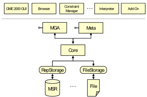
One other system, called Generic Modeling Environment (GME) (Ledeczi et al., 2001) was stud-ied. This system is based on models, and provides a flexible framework, originated in the School of Engineering of the Vanderbilt University (USA), to address essential needs of embedded sys-tems. It is part of the Model-Integrated Computing (MIC) (Karsai, Sztipanovits, Ledeczi, & Bapty, 2003), which focuses on the formal representation, composition, analysis, and manipu-lation of models during the design process. It places models in the center of the entire life-cycle of systems, including specification, design, development, verification, integration, and maintenance (ISIS, 2011).
The GME approach, and its architecture is presented in figure 2.4. It is used for creating domain-specific modeling and program synthesis environments. GME allows a modeller to visually ma-nipulate underlying model data structures. It possesses a graphical user interface (GUI) at the top, a model Browser, Add-ons and a constraint manager. This system also has a persistence Storage Model database and a storage interface. The storage interface includes components for different storage formats (e.g. XML format and a fast proprietary binary file format).
MGA
Core
File MSR
RepStorage FileStorage
…
Meta
GME 2000 GUI Browser ConstraintManager
…
Interpreter Add-OnFigure 2.4:Generic Modeling Environment architecture (Ledeczi et al., 2001)
Analysis:
GME is a system created to work with the model elements (editing models and metamodels). However, it only supports partial model heterogeneity, i.e. it has a representation approach that obligates that the interoperability information has two levels (model and metamodel) of abstrac-tion. GME also does not support model transformations. It presents some functionalities, such as a model browser, add-ons and a constraint manager which gives support for editing the information within GME. The add-ons may support processing on top of the information within. In terms of storage method available, GME uses a Storage Model database.
2. RELATEDWORK: STUDY OFMODEL-DRIVENREPOSITORIES 2.1. Review
Integrated Repository Manager (iRM)
The Integrated Repository Manager (iRM) is another OMG MOF-compliant repository system (Petrov et al., 2004). The architecture of iRM, is presented on figure 2.5. Within the iRM Reposi-tory Management System (RMS), there are four logical modules: Metadata Manager; Lock Man-ager; Consistency Manager and the Data Store Manager. The Metadata Manager is the logical module of the IRM RMS that is directly associated with the MOF metadata architecture, i.e. it organizes the repository objects into the 4-layered OMG reference architecture (Petrov & Buch-mann, 2008). The Consistency Manager is the module which checks and enforces the structural consistency of the repository data, i.e. it checks if every object has a type, or that every association has two association ends. The Lock Manager ensures that an object is not accessed by multiple repository applications in an incompatible manner, it is also used as a session manager, keeping track of the repository applications working with the repository. The Data Store Manager works as an interface to the storage approach, i.e. the Data Store layer in iRM is realized in terms of storage managers implementing a storage manager interface, in order to store data or metadata.
The iRM mSQL engine processes queries formulated in a declarative query language called mSQL, against the repository data. mSQL allows querying attribute values in classes on meta-layer in-stances of a specified meta-class, i.e. it allows model independent querying (Petrov et al., 2004). The mSQL module has two main sub-modules: the mSQL parser which includes partial semantic checker and a logical query plan generator (Petrov & Buchmann, 2008); and the mSQL wrapper containing the implementation of the different operator and mSQL funtions (Petrov & Buchmann, 2008). R ep os ito ry A pp lic at io n Repository Client iR M /R M S A P I
iRM / Repository Management System Metadata Manager D at a S tro re M an ag er Lock Manager Consistency Manager Data Store Metadata Store Data Store M0 XMI Imp/Exp m S Q L W ra pp er mSQL Queries Case Tools
iRM / mSQL
m S Q L P ar se r E xe cu t io n / O pt im i za tio n Naviagtional Access
Figure 2.5:Architecture of iRM (Petrov et al., 2004)
Analysis:
The iRM is another repository based on 4-layered OMG reference architecture. As the iRM data model organizes each element in the 4-layered architecture, it is impossible to manage data that is not compatible with that structure. Both the consistency Manager and Lock Manager are useful modules to ensure the integrity of the information within the repository. The Data Store Manager enables different types of storing, i.e. iRM can persist both data and metadata, which means
2. RELATEDWORK: STUDY OFMODEL-DRIVENREPOSITORIES 2.1. Review
that the elements represented by the data model are stored and the metadata associated with each element may also be stored using the Metadata Store. Another interesting iRM module is the mSQL query engine. This engine allows model independent querying which may ease the way users interact with the information within iRM.
Sun Netbeans Metadata Repository (MDR)
Sun Netbeans Metadata Repository (MDR) is another method encountered (Matula, 2003), and its architecture is presented in figure 2.6. This metadata repository is able to load any Meta Ob-ject Facility (MOF) metamodel and store instances of that metamodel. MDR can import/export metamodels and metadata using XML that conforms to the XMI standard. Metadata within the repository can be managed using the JMI API and the MDR API. MDR provides several func-tionalities, such as enabling that a user can model the language using UML (Matula, 2003). It provides a selection filtering support for querying (Petrov & Buchmann, 2008).
All repository metadata in MDR is persisted using the persistence Service Provider Interface (SPI). The primary storage structure assumed by the SPI is a key-value index. The key is the repository object identifier, while the value contains the repository object in a serialized form. It can be realized by different structures as B-Trees, Hash-Tables, database tables with indices, etc. The default realization is a file based B-Tree store (Matula, 2003). In order to enable users to respond to any changes in the repository, the implementation of the interfaces provided by MDR also handles notifying all the registered listeners of any changes in the metadata they are interested in (Petrov & Buchmann, 2008). Other MDR feature is the support of additional indexing, i.e. enables object indexing using a specified combination of values of several attributes/references. Indexing is used as an add-on to the default B-Tree storage.
Figure 2.6:Architecture of MDR (Petrov & Buchmann, 2008)
2. RELATEDWORK: STUDY OFMODEL-DRIVENREPOSITORIES 2.1. Review
Analysis:
The biggest issue about MDR is that it is no longer available, i.e. Netbeans stopped working on the MDR project and all the latest official documentation is now unavailable. However it is still used in some other projects such as AndroMDA (Bohlen et al., 2007), ArgoUML (ArgoUML, 2005) and EMF (Steinberg et al., 2008). All the information presented here (this analysis included), is based on the white paper (Matula, 2003) and in some articles that during its availability described it (Petrov & Buchmann, 2008). MDR is a repository that stores instances of MOF metamodel as metadata using different storage methods. MDR enables the use of UML to model the language because it has a tool to generate the MOF file based on the given UML model, because the UML language conform to the MOF metamodel. The support of MOF metamodel is important because many of the artefacts use the MOF metamodel, but MDR cannot represent models that conform to metamodels that are not MOF based. It possesses a persistence SPI which supports the use of several storage implementations, which is important because it allows the use of MDR in different environments. It does not allow processing the information within the repository. The query facility provided by MDR could not be analysed due to the fact that no specific information was found.
2.1.2 Synthesis
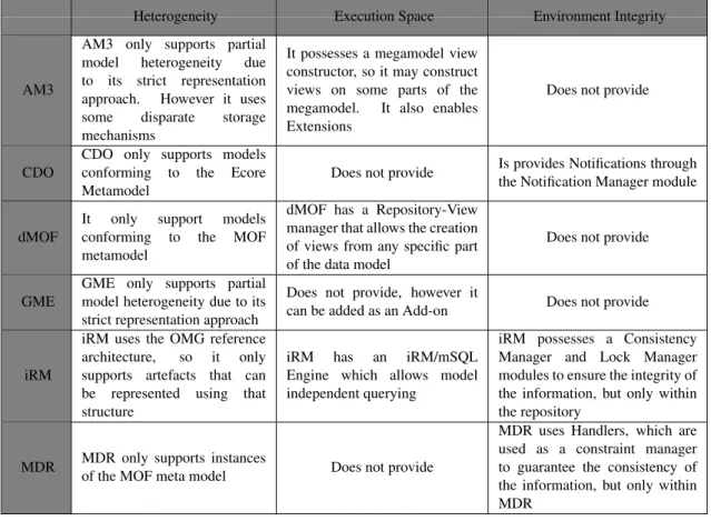
Having already presented and described each of the state-of-the-art element, now the synthesis of each element will be presented and related with the problem characteristics presented before. Table 2.1 presents the author’s point of view in how each state-of-the-art element relates to the previously defined characteristics. Each line of the Table 2.1 represents one system and how that system handles each characteristic (columns).
One can notice that the majority of systems presented can only represent models conforming to one Metamodel. MDR, dMOF and iRM are MOF compliant, and CDO is ECORE compliant. AM3 and GME are not MOF nor Ecore compliant, but use a strict representation approach, meaning that any model not in accordance with it, can not be represented. So, it can be concluded that none of this elements can fully represent heterogeneous interoperability artefacts.
Regarding the need to keep the integrity of the environment, iRM uses a module to verify the con-sistency of the persisted information. This same system and dMOF also have a module responsible for all the management of the metadata persisted. MDR use a different module, which is called Handlers. As the name suggests it handles all the information within the system, and verifies its consistency. This MDR module presents an alternative to the metadata manager and consistency manager modules.
The studied systems also possess some add-ons, which can enable the use of execution of algo-rithms within the repository, such as the possibility of creating views from the data model, pro-vided by dMOF. This feature, which is also used by AM3, may facilitate the use of algorithms on top of the data model, i.e. the algorithms may work on top on a view instead of working directly
2. RELATEDWORK: STUDY OFMODEL-DRIVENREPOSITORIES 2.1. Review
on top of the data model. Some systems also provide specific query languages to allow model independent querying, which is the case of AM3 (provides a megamodel query language), iRM (provides a mSQL Engine) and CDO (Query Manager / Handlers).
In terms of interfaces, all six systems presented, provide methods of interaction with the informa-tion within each by having well-defined interfaces. The majority of them have a repository specific API, but MDR and dMOF also have automatically generated interfaces, i.e. Java Metadata Inter-face (JMI) (Dirckze, 2002) which is the standard for metadata management. The JMI specification enables the implementation of a dynamic, platform-independent infrastructure to manage the cre-ation, storage, access, discovery, and exchange of metadata. The presented systems also have persistence managers which enables the connection to the persistence method available. Systems like dMOF, iRM and GME only provide one (available) persistence method, but AM3, MDR and CDO allows different methods of persistence and different implementations, making it indispens-able to have a persistence manager, which is independent of the storage method used.
Table 2.1:Overview of the Related Work elements
Heterogeneity Execution Space Environment Integrity
AM3
AM3 only supports partial model heterogeneity due to its strict representation approach. However it uses some disparate storage mechanisms
It possesses a megamodel view constructor, so it may construct views on some parts of the megamodel. It also enables Extensions
Does not provide
CDO
CDO only supports models conforming to the Ecore Metamodel
Does not provide Is provides Notifications throughthe Notification Manager module
dMOF
It only support models conforming to the MOF metamodel
dMOF has a Repository-View manager that allows the creation of views from any specific part of the data model
Does not provide
GME
GME only supports partial model heterogeneity due to its strict representation approach
Does not provide, however it
can be added as an Add-on Does not provide
iRM
iRM uses the OMG reference architecture, so it only supports artefacts that can be represented using that structure
iRM has an iRM/mSQL Engine which allows model independent querying
iRM possesses a Consistency Manager and Lock Manager modules to ensure the integrity of the information, but only within the repository
MDR MDR only supports instancesof the MOF meta model Does not provide
MDR uses Handlers, which are used as a constraint manager to guarantee the consistency of the information, but only within MDR
2. RELATEDWORK: STUDY OFMODEL-DRIVENREPOSITORIES 2.2. Advancement
2.2
Advancement
After studying all the systems presented, it was concluded that none of those can fully handle heterogeneous interoperability artefacts. The heterogeneous characteristic of this work is of vital importance due to the need of various interoperability artefacts to achieve interoperability among themselves. AM3, GME and iRM are not metamodel specific, due to using representation ap-proaches not linked with any specific metamodel. From those three, the better suited representa-tion approach is the one used by AM3, the GMM representarepresenta-tion approach. This approach is the only one that represents relationships between information models, and so this work will have a similar approach so it can represent heterogeneous information models, interoperability specifica-tions and the languages that describe each one.
In terms of persistence, the studied systems have one or more storage mechanisms, which may aid the support of heterogeneous information. It is believed that this work must not be linked to any specific storage method. Being tied with some specific implementations, as some of the systems presented, would lead to a non scalable or non evolutionary system. So these work needs to have a persistence manager that will allow the use of different persistence methods and implementations. This is a fundamental characteristic due to the need of supporting heterogeneous interoperability artefacts. With it, the system may be able to choose which storage mechanism fits better to store each type of interoperability artefact.
In terms of interfaces, there is the need to provide methods to interact with the information. Every system studied has a repository specific API which provides this type of methods.Due to these API being repository specific they provide methods in accordance with the information within in order to provide their functionalities to the end users. So, this work will also have a repository specific API in order to enable the user to interact with the information.
Another important aspect is how each state-of-the-art element provides execution spaces. Table 2.1 shows how each one of them handle that characteristic (second column). Both AM3 and dMOF provide a view constructor module so that any application may create views of sections of the information within. MDR and GME only allow model editing and browsing respectively. iRM provides an mSQL Engine. None of them allows the possibility of executing algorithms within the system. So, this work will provide execution spaces, as a major advancement from the state-of-the-art elements. These User Spaces are spaces where a user or application can upload an algorithm and run it from within the system using the interoperability artefacts available.
Another characteristic of this work is the need to keep the integrity of the information in the environment, and for that only CDO possesses a module that accomplishes it. The CDO Noti-fication Manager does exactly what the characteristic needs, it notifies the users or applications upon changes in the artefacts within the repository. MDR and iRM have a Consistency Manager module that keeps the integrity of the information, but only within the repository. This work will use a solution as the one present in CDO, which is a Notification Manager module, allowing the system to keep the environment updated with the last interoperability specifications available.
2. RELATEDWORK: STUDY OFMODEL-DRIVENREPOSITORIES 2.2. Advancement
It was also noticed that the majority of the presented systems are considered repositories. So, the obvious choice to overcome the problem and its characteristics is the use of a repository. Repositories facilitate more efficient storage and management of data formats and interoperability specifications, they also enable sharing and discovery of new information.
3
Interoperability Repository System
3.1
Concept
Repositories facilitate more efficient storage and management of resources, they enable users to share and discover resources shared by others. In this section it is presented some examples of a repository end-user who interacts with it in order to use the functionalities provided. Those users may interact with the repository system in different ways and with different objectives.
One type of end user activities that can be accomplished with the use of the repository is using it exactly as a repository, i.e. a place where the user can store something. In this particular case the user can store an interoperability artefact in the repository and consult it afterwards. In order to accomplish this, the user only has to give the artefact that needs to be stored in the repository, and the repository automatically stores it. This adding, consulting and deleting is just some of the functionalities provided by the repository. This activities represents a simple interaction that a end-user can have with the repository.
It is also needed that the repository provides spaces, in which allows the user to add its own al-gorithms and execute them from within the repository. The ability to update the interoperability related information in the environment is another functionality needed. Another example that may use this repository is an heterogeneous environment where two different formats want to commu-nicate. Imagining two data formats that are unable to understand the messages exchanged between them, so one of them enquires the Repository System for specifications on how to understand that message. The repository than replies with the interoperability related information enabling the communication between those two formats.
3. INTEROPERABILITYREPOSITORYSYSTEM 3.2. Architecture
This repository is to store and manage all this interoperability artefacts and would allow any smart objects to query it for specifications on how to communicate with different data formats whenever needed.
The repository handles information about the interoperability artefact as it handles the actual file, however the repository considers the file as information about the artefact. If any user or appli-cation is in need of an interoperability specifiappli-cation, it can enquire it, as shown in figure 3.1. It is important to understand that the centralized aspect of the figure is due to all the interoperabil-ity artefacts be stored in the same place, and not that the repository will be the centred in the environment.
Repository
Repository
UserSpace
AA B
C
Interoperability Interoperability
Artefacts ??
Heterogeneity User Spaces Integrity
Figure 3.1:Concept
3.2
Architecture
In order to create the repository architecture, it was needed to identify which characteristics this system needed. Those characteristics are:
• Handle Heterogeneity: The repository needs to handle heterogeneous interoperability
arte-facts. It needs to represent information modes, interoperability specifications and the lan-guages that describe each one.
• Provide User Spaces: The repository must provide spaces so the end user of the repository
can upload its algorithms and then execute them fro within the repository, allowing more complex processing using the interoperability artefacts stored.
3. INTEROPERABILITYREPOSITORYSYSTEM 3.2. Architecture
• Update the Environment: The repository must keep the environment up-to-date in respect to
interoperability. It needs to guarantee that the interoperability specifications being used in the environment, are the newer available.
The architecture used in this work is based on the reference architecture for repository systems (Petrov & Buchmann, 2008). In the next few paragraphs it is described the architecture created which obeys to the three layered structure defined by the reference one, with the logical modules within each layer.
• Repository Interface layer: defines a set of methods to expose the repository function-alities to the Repository Applications. This layer exposes functionfunction-alities for storage and retrieval of information, life cycle management, execution of queries against the repository data, etc. The logical modules within this layer are:
– Information Manipulation Interface: enables the manipulation of the information about interoperability artefacts within the repository and allows a user access to the user space interface;
– Configuration Interface: enables the repository configuration, i.e. adding / deleting storage mechanisms, enables subscription of artefacts and notifies the application which subscribed to a new / updated artefact, allows one to manipulate the user spaces pro-vided by the repository, etc;
– User Space Interface: provides access to the Execution Engine, by means of the User Space Specific interface. This allows a user to interact with a specific User Space.
• Repository Management System (RMS) layer: it is in this layer that all the processing occurs, i.e. this layer may have a set of modules responsible for managing the informa-tion, allowing several operations to be executed; This layer possesses the following logical modules:
– Metadata Manager: It provides the comprehension of all the artefacts stored in the repository;
– Notification Manager: module responsible to manage subscriptions of artefacts;
– Execution Engine: module that executes algorithms to enhance the functionalities of the repository;
• Persistence layer: This layer represents the set of persistence providers working with the repository system and the module that handles them. This persistence providers can be a relational database, flat files, index files, etc.:
– Persistence Management: Module that handles the persistence of the actual files and manages the storage mechanisms available;
– Storage Mechanism: it represents any storage mechanism available.
3. INTEROPERABILITYREPOSITORYSYSTEM 3.3. Logical Architecture Specification
The architecture created is presented in figure 3.2, where these three layers are explicit, and all the logical modules are presented.
Storage Mechanism 1
Persistence Management Notification
Manager ExecutionEngine
Metadata Manager Information Access
Interface Repository
Applications
Repository Interface
Repository Management
System
Persistence Layer
Configuration Interface
Storage Mechanism N Storage
Mechanism 2 ...
User Space Interface
Figure 3.2:Logical Architecture
3.3
Logical Architecture Specification
This section will provide a specification of the logical modules present in each layer. Each logical module has a description of its objectives and the methods each one provides. Figure 3.3 presents an example of a logical module. It has sets of methods on top (API), which are methods available to other modules to use. The ones in the bottom (Caller Interface) are methods that the module uses to communicate with the other modules. Each of the logical module described next has a figure such as this one in order to explain its own methods.
Figure 3.3:Example of a module with the API and Caller Interface
3. INTEROPERABILITYREPOSITORYSYSTEM 3.3. Logical Architecture Specification
3.3.1 Persistence Layer
This layer, as the Repository Applications layer, presents all the storage mechanisms that may be used by the repository to store the artefacts that it has to persist. This storage mechanism can be of many types, i.e. databases, files or main memory. It also presents the Persistence Management module. It is important to understand that is in this layer that the actual files of the interoperability artefacts are handled and stored. The Persistence layer and its logical modules are present in figure 3.4.
Storage
Mechanism 1
Persistence Management
Storage
Mechanism N
Storage
Mechanism 2 ...
Figure 3.4:Persistence layer and its logical modules
Storage Mechanism
All the storage mechanisms within this Persistence layer need to be registered in the Persistence Management module, so the repository knows its existence and which artefacts are being persisted for each mechanisms. Present in figure 3.5 is an example of a Persistence Layer module. This example presents a general storage mechanism which can be a database, File system or main memory. It presents CRUD methods in the API, so the repository can store or delete the actual files.
Figure 3.5:Example of a Persistence Layer module
Persistence Management
This module is responsible for the management of the persistence mechanisms being used by the Repository. It also keeps track of which files are stored within each storage mechanism. Whenever this module receives a file it stores it in one of the storage mechanisms available. The Persistence Management module and its methods are present in figure 3.6.
3. INTEROPERABILITYREPOSITORYSYSTEM 3.3. Logical Architecture Specification
Figure 3.6:Persistence Management module
This Persistence Management module indexes the files with the storage mechanism where it is stored, it is also where the storage mechanisms are registered so it can always know which storage mechanisms are available. Another important characteristic of this module is that this module is the one responsible for choosing which storage mechanism to use whenever a new file needs to be stored. That choice is based on the type of the interoperability artefact, considering which storage mechanisms available.
This module has a set of CRUD methods, which are the four basic functions of persistent storage (Create, Retrieve, Update and Delete) (Martin, 1983). This methods allow the other modules to add, update, delete or retrieve information from this module. The Manage Storage mechanism reg-istration is a set of methods to subscribe, unsubscribe or manage the storage mechanisms available. The module also has a persistence interface (as a Caller Interface) which allows the communica-tion with the storage mechanisms in order to request the addicommunica-tion or removal of a specific file.
3.3.2 Repository Management System Layer
The RMS layer possesses all the logical modules responsible for processing the information within the repository. This layer is where the interoperability artefacts (excluding the files, which are handled in the persistence layer) is handled. Within this layer there are three different logical modules, which can be observed in figure 3.7:
Notification
Manager ExecutionEngine
Metadata Manager
Figure 3.7:Repository Management System layer and its logical modules
3. INTEROPERABILITYREPOSITORYSYSTEM 3.3. Logical Architecture Specification
Metadata Manager
Metadata Manager is the logical module responsible for the representation of all interoperabil-ity artefacts. This module needs a representation approach similar to GMM (the representation approach used by AM3), that can represent heterogeneous information. Figure 3.8 presents the Metadata Manager module and its methods.
Figure 3.8:Metadata Manager module
The interaction with this logical module mainly consists in basic adding, retrieving, updating or deleting (CRUD methods) information about artefacts. To have the meta-information of all arte-facts means that it needs use unique identifiers. The metadata manager is responsible to generate these unique identifiers so each interoperability artefact has its own identifier. This Metadata Manager module possesses CRUD Methods on its API, in order to enable the other modules to manipulate the information within.
Notification Manager
This module is responsible for notifying repository application whenever there is a change in the artefacts within the repository. This notification services are useful for several modelling applications that are performing complementary operations with the same artefact. This is also important to maintain updated the interoperability specification being used within the environment. Figure 3.9 shows this Notification module with its own methods.
Figure 3.9:Notification Manager module
This module possesses an API method called: Manage Application subscriptions, which exists in order to provide the methods to manage subscriptions. It allows an application to subscribe to one or several artefacts and when there is a change in the subscribed artefacts it notifies the application. In the Caller Interface, it possesses two methods that serve as a connection between this module and both the Metadata Manager and the Persistence Management module, so the Notification Manager module can notice whenever an artefact (file and/or meta-information) is changed in the model module.
3. INTEROPERABILITYREPOSITORYSYSTEM 3.3. Logical Architecture Specification
Execution Engine
This is the module responsible for all the user defined operations executed, using the Generic Data Interface to communicate with the other modules. This execution engine can perform more complex tasks, such as traverse algorithms and statistic determinations. Figure 3.10 shows the Execution Engine module and both its API and Caller Interfaces.
...
User Space Interfaces Execution Engine
Management
User Space 1
User Defined Interface
User Space 2
User Defined Interface
Execution Engine
User Space N
User Defined Interface User Specific Access (Metadata) User Specific Access (Persistence)
Figure 3.10:Execution Engine module
This Execution Engine module provides User Spaces in order to allow one user to add its own algorithm to the repository. The repository provides two sets of methods in its own API: the Execution Engine Management, which are the methods provided to manage the user spaces, such as the addition of removal of a algorithm from one User Space; and the User Space Interfaces, which are the methods provided by each algorithm, that are present in figure 3.10 as the API of each User Space. Each algorithm may use the User Specific Access methods (The Execution Engine Caller Interface) to use the functionalities provided by the other modules.
3.3.3 Repository Interface Layer
In order to allow user interaction, the repository needs to support a well-defined interface with different methods. Each method may have different abstraction levels, and have distinct objectives. From a more functional point of view, this repository needs to be associated to a set of services. These services can be used to query the repository for interoperability artefacts, allowing the user to enhance the repository’s interoperability specification, add/remove entities or relationships to/from the repository, as well as, to attach new information about an existing artefact.
One important aspect, is that all the control flow is on this layer, which means that it is the Interface modules that control the execution flow of each action that the user wants executed. For example, in the case that a user need to add a file to the repository, he calls the Add method (included in the CRUD methods) from the Information Manipulation Interface module and inserts the file there. Afterwards, this interface module interpret the file to retrieve its meta-information and asks the Model module for a Unique Identifier to use with this new artefact. After gathering all that