Underwater communications for moving source using geometry-adapted time reversal and DFE: UANIO data
U. Vilaipomsawai, A. J. Silva and S. M. Jesus
Instituto de Sistemas e Rob6tica, Universidade do Algarve, Campus de Gambelas, 8005-139 Faro, Portugal
Abstract-This work presents an improved version of our previously proposed technique, i.e. the combined geometry adapted passive Time Reversal (pTR) and Decision Feedback Equalizer (DFE) for underwater communications between a moving source and a fixed receiver array (implying a range change) [1]. Since the geometry change can be compensated by employing a proper frequency shift on the probe Impulse Response (IR) in the pTR processing, the geometry-adapted pTR is called Frequency Shift pTR (FSpTR). A slot-based FSpTR processing is performed, where frequency shifts applied to the IRs can change over slots to compensate for geometry changes over time. The FSpTR output is the concatenation of slots of the processed signals. With different frequency shifts for consecutive slots, there are phase jumps in the FSpTR output. In this work, we propose a new phase-jump correction method, which is stable with respect to IR time-window selection. After the phase correction, a standard phase synchronization method and the DFE can then be applied subsequently to the FSpTR processing to further improve the performance. The developed technique is named FSpTR-DFE. Experimental data collected off Pianosa island, Italy in September 2010 for Underwater Acoustic Network (UAN) project, is called UANI0 data and used in the evaluation of the FSpTR-DFE performance. An information rate up to 2400 bps and BPSK signaling are considered. The results show that the FSpTR-DFE technique outperforms the FSpTR as well as the technique combining the conventional pTR with DFE when there exist strong range changes.
I. INTRODUCTION
Underwater channels are among the most challenging for digital communications. Large multipath delay spread causes severe Inter-Symbol Interference (lSI), and surface waves, as well as the relative motion between source and receiver, cause fast time-variant fading and Doppler shifts. To combat such severe conditions, a receiver array providing spatial diversity is usually required. In this work, we consider a pTR technique, where a source first transmits a probe signal to sample the channels, followed a data-bearing signal. At the receiver, the received data signals are cross-correlated with the corresponding time-reversed received probe signals and spatially combined to provide the pTR output. This system is considered as a Single Input Multiple Output (SIMa) communication system. To address the time-varying channel effect, caused by a moving source/receiver, the geometry adapted pTR technique was proposed in [2], [3]. It was shown that by employing a frequency shifted version of the estimated channel impulse response in the pTR processing, geometric changes can be partially compensated. Hence, the technique of [3] is referred to as Frequency Shift pTR
978-1-61284-4577-0088-0/11/$26.00 ©2011 IEEE
(FSpTR). Although a pTR-based technique can mitigate the lSI problem, an equalizer is required to eliminate the residual lSI as shown theoretically in [4]. Hence, in [5], [6], [7], performance improvement techniques of the pTR using an adaptive DFE are proposed.
In this work, we propose the FSpTR-DFE technique, where the FSpTR is combined with DFE (rather than the pTR as in [6], [7]) to compensate for geometry changes. Also, the FSpTR-DFE operated in decision directed mode is considered, i.e. only a short training sequence is required at the beginning of the transmission. In the FSpTR technique of [2], [3], frequency shifted probe Impulse Responses (IRs) are used in place of the original probe IRs in the pTR processing. A slot-based FSpTR processing is performed, where frequency shifts applied to the IRs can change over slots to compensate for geometry changes along time. The concatenation of slots of the processed signals forms the FSpTR output. There are phase jumps in the FSpTR output, when different frequency shifts for consecutive slots are used. In this work, we address the phase jump problem and propose a new correction method so that a standard Phase Locked Loop (PLL) can be used for phase synchronization and the DFE can be applied. The method is based on the phase of the frequency shifted pTR outputs, obtained as a byproduct in the FSpTR processing, while in [1] another method based on the phase of the Q function [8] was proposed.
This paper is organized as follows: Sections II and III present the brief reviews of the pTR and FSpTR techniques, respectively. The techniques have been discussed in [1], and are presented in this paper for completeness of the presentation. Then, the FSpTR-DFE technique is discussed in Section IV, followed by the UANlO experimental setup for Point to Point (P2P) communications in Section V. Section VI presents the performance evaluation of proposed technique using UANlO data. Finally, the conclusions are drawn in Section VII.
II. PASSIVE TIME REVERSAL TECHNIQUE Throughout this paper,
(
-)
* and*
denote complex conjugate and convolution operators, respectively. For a given function
a(u),
denotea(u)_
=
a( -u).
Considerc(t; u)
a function of timet
and a variableu,
and define the convolution betweena(·)
andc(t;·)
byConsider a noise-free pTR system, the baseband pTR output is given by
00
z(t)
=L
dk qt(t -kT )
(2)k=-oo
where
{dk}
is a data sequence, transmitted at symbol rate�
withT
being a data symbol period, andqt (t')
is an effective IR as seen after the pTR processing and is given bywith
PNq(t)
being a Nyquist pulse, and'Yt(t')
E�=l
(
cm(t;.) * c;"(to; .)-
)
(t').
(3)
From (2), the discrete-time signal of the pTR output, sampled at symbol rate
Zk
=z(t)lt=kT
can be expressedas
Zk
=dkqkT(O)
+
L
d1qkT((l-k)T )
(4)1#
The first term in (4) is the scaled and phase rotated version of
dk,
and the second term is the lSI.With assumptions that channels are static, the IR es timation is perfect and a receiver array is dense and long,
'Yt(t')
would be an impulse-like signal [8], due to the focusing property of the pTR. Then,qkT(O)
=E�=l J Icm(kT; T)12dT
would be real and positive. Hence, we would haveZk = qkT(O) . dk,
which is a scaled version ofdk
with no-phase-rotation. For coherent communications, an error-free transmission would be achieved since only the phase of signal conveys the information.In reality, however, such assumptions can never be re alized. Then, the pTR focusing ability is decreased due to degradation of the impulse-like behavior of
'Yt(t')
and the effect of lSI is observed. This fact motivates the development of the FSpTR [3], discussed in Section III.III. FSpTR TECHNIQUE
Based on the work presented in [3], geometric changes can be partially compensated by applying a proper frequency shift to the channel response estimate in the pTR processing.
Define
qt(t')
associated with a frequency shiftf
asq�f)(t')
=(
PNq(·) *'Y�f)(-)
)
(t')
(5)where
'Y�f)(t')
=E�=l
(
cm(t;·) * c}t)*(to;·)-
)
(t')
withc}tl(to; T) = cm(to; T)e-j27rfT.
Then, let
z(t)
associated withf
be given by00
z(f)(t)=
L
dk q�f)(t-kT)
(6)k=-oo
In the FSpTR scheme,
z(f) (t)
is calculated forf
E :F ={11,12,
..
.,fNf}'
where eachz(f)(t)
is divided into time slots,i
=1,2,
...
, l
¥a
J
withTF
andTo
being frame andslot durations, respectively, and the energy of
z(f) (t)
in time sloti
is defined as Ez(f)(i)
=J(��l)To Iz(f)(t)12dt.
Let the maximum energy over all slots
i
=1, .
..
, l
ib
J
andf
E :F denote byEmax
=maxi,!
Ez(f)(i).
At sloti,
let afrequency shift be selected based on the maximum energy criterion as
f(i) =
argmaxfE.'F Ez(f)(i).
A large swing of frequency shifts in consecutive slots with low energy causes a difficulty in phase jump correction [1], while does not offer a significant gain. To prevent such swing, we impose the condition that a frequency jump is not allowed if the frequency jump between slotsi
andi-I
is greater than the threshold'T]f
Hz and the normalized energyEzi{�;�� (i)
is below'T]E.
Hence, we updatef(i)
sequentially fori
=2, .
.
., lib
J
as follows:f(i)
=f(i-1)
ifIf(i)-f(i-1)1
>'T]f, Ezi{�;��(i)
<'T]E, f(i)
=f(i)
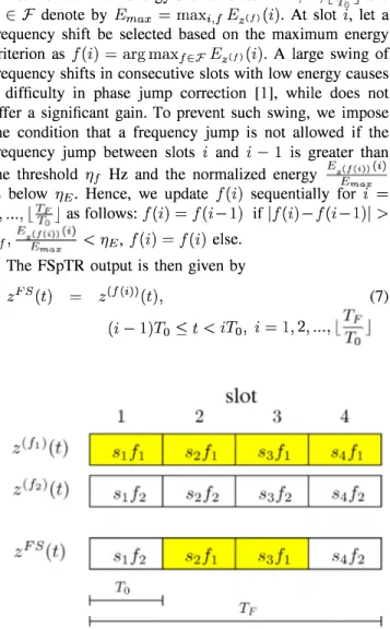
else.The FSpTR output is then given by
zFS(t)
=Z(f(i)) (t),
(7)(i -l)To:S: t
<iTo, i
=1,2,
...
, l
i
J
Fig. 1. FSpTR output, i.e. the concatenation of slots of processed signals
with maximum energy, selected over a set of frequency shifts
Fig. 1 graphically illustrates the slot-based
z(f) (t)
forf
E :F ={11, 12},
where we use"sd/'
to represent the sloti
associated with frequency shiftfJ.
Assume that selected frequency shiftsf(i)
associated with slotsi
= 1,2,3,4are
12,11,11
and12,
respectively. Fig. 1 also shows the FSpTR output which is the concatenation ofz(f(i))(t)
slots associated with the selectedf (i).
The
f(i)
is expected to change over the frame to com pensate for geometry changes, and can change abruptly from one slot to another. Hence, phase jumps ofzF S (t)
at the boundaries between consecutive slotsi
andi
+
1
withf(i)
=I-
f(i
+
1)
(e.g. slots 1 and 2, as well as 3 and 4 in Fig. 1), are expected.received signal
P hase jump compensation
Doppler est. &
compensation
Output normalization
FSpTR output
FSpTR-DFE
Fig. 2. FSpTR-DFE scheme
I V. FSpTR-DFE SCHEME
This section discusses the FSpTR-DFE scheme as shown in Fig. 2, which consists of FSpTR, phase jump compen sation, Doppler estimation/compensation, symbol and phase synchronizations, output normalization, and adaptive DFE data-processing blocks.
To be able to use a standard PLL for phase synchroniza tion and adaptive DFE after the FSpTR processing, the phase jumps need to be corrected. Since z(f) (t) is required and used in the maximum energy criteria, as a by product, we can calculate the phase jump associated with frequency shifts
f(i + 1)
andf(i)
from z(f)(t) byLp
¢(i + 1)
=�
"(
Lz(f(i+1)) - Lz(f(i)))
(8)L L...J .To+k .To+k
P k=O
·th
"' (1)
- 1"Lp
(
/ (f(1)) / (0))
Thi h dWI 'f/ -
Lp
L..Jk=O LZiTo+k - LZiTo+k ' S met 0is more stable than that based on
¢(i + l)
= Lqg
�
i+1))(0)_Lq
g
�
')) (0) presented in [1], with respect to time-window size of IRs (shown later). Here, we refer to the phase correction methods in (8) and [1], as "PCZ" and "PCQ", respectively.Since the phase also gradually changes within a slot, to compensate for phase jumps we need to consider accumu lated phase at slot
i
as given by¢a(i)
=L
¢(j)
(9)j=1 where
¢(j)
is obtained from (8).The phase corrected output of the FSpTR is given by zFS,c(t) zFS (t)e-j¢a(i) = z(f(i)) (t)e-j¢a(i)
,
(10)(i - l)To
::; t <iTo, i
=1,2,
..., l
i
J
Doppler compensation, symbol synchronization and out put normalization are done using the method presented in [9] as discussed in [1]. For an adaptive DFE, we employ the joint phase correction and DFE based on the first order PLL and the Recursive Least Square (RLS) algorithm.
V. UAN lO E XPERIMENT: P2P COMMUNICATIONS This section presents P2P communication setup, con ducted off Pianosa island, Italy during September 7-25, 2010 for Underwater Acoustic Network (UAN) project. Various P2P configurations were conducted in this experiment by changing the locations of the source, while fixing the Vertical Line Array (VLA). There were three sets of P2P communi cation experiments, where the source was placed at various locations, 1. from the Pianosa's pier, 2. from the rubber boat, moving due to current, and 3. from stationary Leonardo, the NURC research vessel. In this paper, we consider only the rubber boat P2P case since there was source movement with respect to the fixed VLA. Fig. 3 illustrates the bathymetry of the experimental area. The blue '+' marks the VLA position
with water column depth of about 56.6m. The blue 'x' marks the pier at Pianosa island. Also, the blue boat track is shown in Fig. 3. Red '0' and
'0'
on the track mark the nominalsource positions at transmission frames 1 and 2 (denoted by Fl and F2), respectively, considered in this work. The seafloor of area is sand with occasional rockslboulders.
Fig. 3. P2P communication area with VLA and source positions
The VLA consists of 16 hydrophones, with the first hydrophone depth of 11.1 m from the surface and
approxi-mately 2m spacing. An acoustic source was placed from the rubber boat at depth 11m below the surface. Fig. 4 presents the Sound Speed Profile (SSP) for September 13, 2010, during the time of boat P2P experiment. The downward refracting SSP with starting depth of thennocline at around 22m is observed. The VLA is also presented in the Fig. for reference. 10 �20 .s .<::
g.
30 o 40 50 VLA 1505 151 0 1515 1520 1525 1530 1535 1540 Sound speed (m/s)Fig. 4. SSP for September 13, 2010, at 7:24 GMT
Various BPSK modulated signals, different in terms of frequency band, data rate, bandwidth, denoted by Cl to C3 with specifications given in Table I, were sent for this P2P experiment. To illustrate the benefit of FSpTR-DFE for range-change scenarios, we consider C2 and C3 signals from the data frame F1, where the boat (or the source) moved due to current with maximum speed of 0.2m1s (estimated from GPS data) at the nominal range between the source and VLA of 320m. Since the C1 signal in the aforementioned frame was corrupted, we consider a C 1 signal from frame F2, associated with low source speed of 0.00 1 mls at range 4l2m from the VLA.
VI . PERFORMANCE EVALUATION: UAN lO DATA This section presents the Mean Square Error (MSE) and Bit Error Rate (BER) performance of the proposed scheme. For this data set, we use the combined pTR with an equalizer (e.g. Linear Equalizer (LE) and Decision Feedback Equalizer (DFE)), denoted by pTR-E and FSpTR with an equalizer, denoted by FSpTR-E. In the following, we present parameters used in all equalizers (complete notations can be found in [1]). The forgetting factor >. = 0.995 is employed
for the RLS algorithm. A slot duration of To = Is is used for
frequency shift decision making and To = 0.05s is considered
in the Doppler frequency estimation. We consider a set of candidate frequency shifts F =
{
-300, -275, ... , 275, 300}
,the threshold for frequency jump 'TIf = 300 Hz and that
for normalized energy 'TIE = 0.6. Moreover, in discrete
time signals L = 4 samples per symbol is considered. Only
a training sequence of length 200 symbols is required for C1-C3 signals. Here, we account for the training symbols used only in data processing, i.e. for frame, symbol and phase synchronizations, and the symbol-spaced LE and DFE, while assuming that channel IRs can be estimated from other means, such as using M-sequence or chirp signals. Note that in this work we use M-sequences of length 63, 127, and 255 symbols for C1 to C3 channel IR estimations, respectively. In the adaptive LE, 20 feedforward coefficients consisting of 10 causal and 10 anticausal coefficients are used, while in the DFE addition 10 feedback coefficients are used.
iii' � w en :2: 5 .---�---�---�---, 0 -5 -10 -15 0 x pca 0 PCl -C2 - - C3 /'. 1'; ,l '. i
\
;l ' l , I \ I \ /". ..£] _ _ D- . e -0 -&- a. !II.. It. . ...a.
-0.01 0.02 0.03 0.04
IR time window (5)
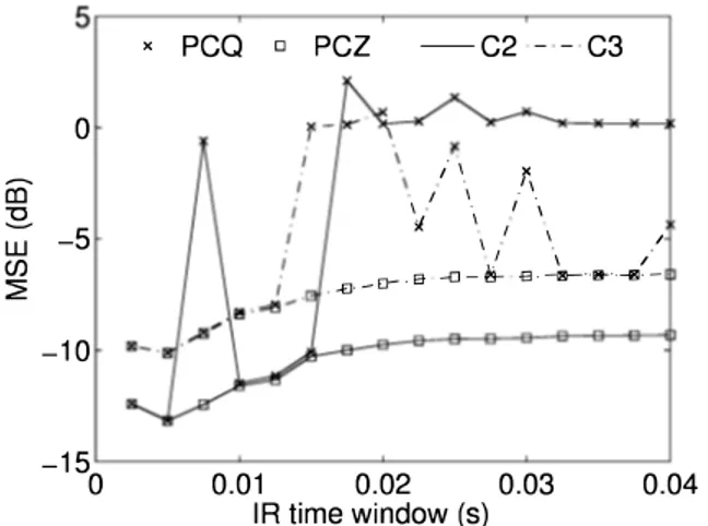
Fig. 5. Impact of TW on MSE of FSpTR-DFE with PCZ and PCQ
To illustrate the advantage of the new method for phase jump correction (i.e. PCZ) over PCQ of [1], the effect of Time-Window (TW) size of IRs on MSE of FSpTR-DFE using PCZ and PCQ is investigated. Fig. 5 shows the MSE of FSpTR-DFE using PCZ and PCQ as a function of
TW
for simulated C2 and C3 signals. The channel simulator developed at CINTAL [10], [11] is used. We observe that a shortTW
(containing only first arrival, or first group of arrivals) provides a better perfonnance than the long ones. This is due to a more stable of first arrival than later arrivals, resulting in a better time coherence between probe short time-windowed IR with those during data transmission. A similar observation is also found in [9]. Moreover, FSpTR DFE with PCZ provides a more stable MSE than that with PCQ for larger TW size, eventhough those with PCZ and PCQ provide the same MSE for short TW. Hence, the PCZ is more robust than PCQ and can be used when TW are selected automatically.Fig. 6 shows the frequency shifts used in FSpTR for simulated C2 signals, and the phases of FSpTR output without phase jump correction (NoPC) and those with PCQ and PCZ, tracked by the PLL. For NoPC case, we observe phase jumps between consecutive slots, while for PCZ and PCQ, a smoother phase is observed.
Table II summarizes the MSE and BER performance of the pTR, FSpTR, pTR-E and FSpTR-E schemes using
TABLE I
SIGNA L COD E S USE D IN THE P2P EXPERIMENT AT PIANOSA I SLAND
Code Type Duration Carrier Freq. Baud Start-Stop Bandwidth
N :E-.t::
T
Ie
(s) (kHz) C1 BPSK 20 5 C2 BPSK 20 10 C3 BPSK 20 15 o .---.---.---�.---�.---,� -200
C" � LL-400
L-�---�---�----�----��2
4
Slot 6 810
8,-�---�--���----�---� '06�
Q)4
en til6:2
----pca - - - PCZ - - NoPC _---... -_ ..2
4
6 Time (5) Fig. 6. Phase jump correction... ,.. . ... ... ...
8
10
VAN 1 0 data. Moreover, Table II presents
id
used in this data set. In this paper, short time-windowed IRs covering only first group of arrival are considered since they provide better performance than the long ones (well agree with results in Fig. 5). As a result, the performance of the FSpTR DFE scheme using PCZ and PCQ phase correction methods is the same. This observation is also in agreement with that presented in Fig. 5. Hence, only FSpTR-DFE results using PCZ phase correction method is presented in Table II. The results show that the FSpTR-E scheme with both LE and DFE provides a gain in terms of MSE over the pTR-E scheme for C2 and C3 signals. Moreover, the DFE provides gain over the LE when used with the pTR or FSpTR schemes. For Cl signal, the pTR-E and FSpTR-E perform comparable since the source is almost fixed for this case. For this data set, an error-free communication using the FSpTR DFE technique can be achieved, with data rate upto 2400 syrn/s.In pTR-based techniques, the temporal coherence of chan nel IRs with respect to probe IRs as in [1], [8] is a key factor determining the system performance, where the coherence is defined to be the maximum cross-correlation between two signals normalized by the product of the square root of
Rate Freq. (symb/s) (kHz) (kHz) 600 4.55-5.45 0.9 1200 9.1-10.9 1.8 2400 13.2-16.8 3.6 TABLE II
MSE AND BER PERFORMANCE OF pTR, FSpTR, pTR-E AND FSpTR-E FOR UANlO DATA
MSE (dB) MSE (dB)
Case
id
pTR FSpTR Eq. pTR-E FSpTR-ECl -1.6 -7.6 -7.8 LE -22.9 -22.7 DFE -23 -23 C2 -3.0 -6.1 -6.5 LE -15.1 -17.2 DFE -17 -18.4 C3 -4.6 -3.7 -6 LE - 1 1 .6 - 1 5. 1 DFE - 1 2.6 - 1 6 BER (%) BER (%)
Case pTR FSpTR Eq. pTR-E FSpTR-E
Cl 0 0 LE 0 0 DFE 0 0 C2 0.1 0.1 LE 0 0 DFE 0 0 C3 2.9 0.43 LE 0.03 0 DFE 0.009 0
maximum autocorrelation of each signals. Here, we consider two sets of IRs, one is the array of probe IRs and another is that of IRs during data transmission. The cross-correlation and autocorrelation used in the coherence calculation are defined as the sum over individual cross-correlations and autocorre1ations, respectively. Fig. 7 presents the temporal coherence between sets of IRs during 20s transmission with that of
TW
probe IRs for C l-C3 cases. The results show that the coherence times (defined as the time that the coherence decays to e-1 � 0.37 [8]) for C1 and C2 signals are longerthan 20s, while that of the C3 signal is around lOs. Also, we investigate the temporal coherence of channel IRs with respect to frequency shifted
TW
probe IRs as shownin Fig. 8, where the frequency shifts are provided by the FSpTR processing. We observe that the coherence is clearly improved in all cases. These results explain the performance improvement obtained by the FSpTR over the pTR, resulting in a better performance of the FSpTR-DFE with respect to the pTR-DFE. CI) u <: � � 0.6 o o � 8.0.4 E � 0.2 ---a---C1 ---&-C2 --+--C3 5 10 Time (s) 15 20
Fig. 7. Temporal coherence of channel IRs with time-windowed probe
IRs for UANlO data
CI) u <: � � 0.6 o o � 8.0.4 E � 0.2 ---a---C 1 ---&-C2 --+--C3 5 10 Time (s) 15 20
Fig. 8. Temporal coherence of IRs with frequency shifted time-windowed probe IRs for UANlO data
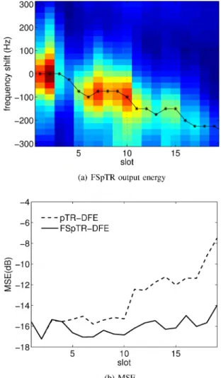
Fig. 9 illustrates the FSpTR energy associated with fre quency shifts and MSE for experimental C3 signal, using the pTR-DFE and FSpTR-DFE. In this source movement case, the FSpTR-DFE using frequency shifted IRs that track the maximum FSpTR output energy, can compensate for range changes. Hence, the FSpTR-DFE technique provides a superior performance over the pTR-DFE technique.
From the results presented in this section, the advantage of using the FSpTR in the FSpTR-DFE is clearly observed for communications over time-varying channels, caused by range changes.
Fig. 9. Performance of pTR-DFE and FSpTR-DFE schemes for UANlO C3 signal.
VII . CONCLUSION
This work presents a more stable phase-jump correction method used in FSpTR-DFE scheme, which is the combi nation of geometry-adapted pTR and adaptive DFE tech niques for moving source over shallow-water channels. The method, called PCZ, is based on the phase of the frequency shifted pTR outputs, obtained as a byproduct in the FSpTR processing, while the previously proposed method, named PCQ, is based on the phase of the Q function. The results show that the FSpTR-DFE technique using PCZ is less sensitive to time-window selection of IRs as compared to that using PCQ. The MSE and BER performance of the FSpTR-DFE scheme is evaluated using UANlO data. In addition, the temporal coherence of the channels is inves tigated. The results show that the coherence has a strong impact on the performance of pTR-based techniques. The FSpTR can increase the coherence, which make the FSpTR DFE outperformed the pTR-DFE. Furthermore, using the FSpTR-DFE, data transmissions with rate upto 2400 BPSK
sym/s with MSE of less than -15 dB can be realized. Hence, the FSpTR-DFE scheme could be a candidate scheme for high data rate, sustainable and reliable communications over rapidly time-varying underwater channels.
ACKNOWLE DGE MENTS
This work is supported by European Commission's Sev enth Framework Programme through the grant for Underwa ter Acoustic Network (UAN) project (contract no. 225669). The authors would like to thank the Italian Navy for provid ing the RN Leonardo to conduct the UANl O experiment, as well as the support from Leonardo master and crew. Also, our gratitude is extended to the NATO Undersea Research Centre (NURC) team, lead by Dr. John Potter, and to all UAN personnel involved in the experiment.
REFERENCES
[1] U. Vilaipomsawai, A. Silva and S.M. Jesus, "Combined adaptive time reversal and DFE technique for time-varying underwater communications," in Proc. European Conference on Underwater Acoustics (ECUAIO), July 2010.
[2] A. Silva, S.M. Jesus and J. P. Gomes, "Environmental equal izer for underwater communications," Proc. IEEE Oceans '07,
Oct. 2007.
[3] A. Silva, "Environmental based underwater communications," P h.D. dissertation, University of Algarve, 2009.
[4] M. Stojanovic, "Retrofocusing techniques for high rate acous tic communications," J. Acoust. Soc. Am., vol. 117, pp.
1173-1185, March 2005.
[5] G.F. Edelmann, H.C. Song, S. Kim, W.S. Hodgkiss, w.A. Ku perman and T. Aka!, "Underwater acoustic communications using time reversal," IEEE J. Ocean Eng., vol. 30, no. 4, pp.
852-864, Oct. 2005.
[6] T. Yang, "Correlation-based decision-feedback equalizer for underwater acoustic communications," IEEE J. Ocean Eng., vol. 30, no. 4, pp. 472-487, Oct. 2005.
[7] H.C. Song, W.S. Hodgkiss, w.A. Kuperman, M. Stevenson and T. Akal, "Improvement of time-reversal communications using adaptive channel equalizers," IEEE 1. Ocean Eng., vol.
31, no. 2, pp. 487-496, April 2006.
[8] T. Yang, "Temporal resolution of time-reversal and passive phase conjugation for underwater acoustic communications," IEEE 1. Ocean Eng., vol. 28, no. 2, pp. 229-245, April 2003.
[9] J. Gomes, A. Silva and S.M. Jesus, "Adaptive spatial com bining for passive time-reversed communications," 1. Acoust. Soc. Am., vol. 124, pp. 1038-1053, Aug. 2008.
[10] O.c. Rodriguez, A. Silva, F. Zabel and S.M. Jesus, "The TV APM interface: a web service for collaborative modeling," in Proc. European Conference on Underwater Acoustics (ECUA'IO), July 2010.
[11] O.c. Rodriguez, A. Silva, J.P. Gomes and S.M. Jesus, "Mod eling arrival scattering due to surface roughness," in Proc. European Conference on Underwater Acoustics (ECUA'IO), July 2010.