Simulating Intermediate Crack Debonding on RC Beams Strengthened
with Hybrid Methods
Abstract
The externally bonded (EB) and the near-surface mounted (NSM) are two well-known methods for strengthening reinforced concrete (RC) beams. Both methods are unfortunately prone to fail prematurely through debond-ing when the amount of strengthendebond-ing reinforcement provided is high. In response to this, a hybrid method that combines the EB and NSM method was introduced. The method allows the amount of reinforcement needed for EB and NSM methods to be reduced; this, in theory, should lower the inter-facial stresses, thus reducing the possibility of debonding failures. While debonding failure can be prevented, certain amounts of debonding would still occur through the interfacial crack (IC) debonding mechanism which can affect the strength and stiffness of hybrid strengthened beams even if it does not directly cause failure. This paper presents a method to simulate IC debonding of hybrid strengthened beams using the moment-rotation ap-proach. The proposed method allows a better prediction of maximum load and stiffness of the beams. The method is also less dependent on empirical formulations compared to the commonly used moment-curvature ap-proach; this allows the method to be applicable to all material and shape of hybrid strengthening reinforcement, assuming correct material models are used. The proposed method was then used to perform parametric studies; among the important findings is the length of IC debonding tend to increase when FRP sheet with higher elastic modulus is used, thus negating most of the benefit from the higher modulus.
Keywords
Externally bonded; fibre reinforced polymers; near-surface mounted; nume-rical analysis; partial-interaction; reinforced concrete.
1 INTRODUCTION
There are generally two types of strengthening methods available for reinforced concrete (RC) structural members in flexure: the externally bonded (EB) method (Barros et al., 2017; Ceroni et al., 2008; Chen et al., 2016; Fabrics et al., 2003; Maalej, 2005; Pesic, 2005; Tam et al., 2016; Toutanji et al., 2006) and the near-surface mounted (NSM) method (Badawi and Soudki, 2009; Capozucca et al., 2016; Capozucca and Magagnini, 2016; Kreit et al., 2011; Pachalla and Prakash, 2017; Seo et al., 2016). The EB method uses either fibre reinforced polymer (FRP) plates or sheets that are attached on the soffit of RC beams using epoxy adhesive. The NSM method involves making a groove on the soffit of RC beams and inserting either FRP bars or strips into the grooves and filling them with epoxy adhesive.
Both of these methods are prone to one or more types of debonding failures. An EB strengthened RC beam can fail prematurely due to either critical diagonal crack (CDC) debonding, interfacial crack (IC) debonding or end debonding (Narayanamurthy et al., 2012). On the other hand, NSM strengthened RC beams tend to fail prematurely only from end debonding through concrete cover separation (Zhang and Teng, 2014). While the NSM method is less prone to IC and CDC debonding failures, the probability of concrete cover separation failure is significantly high and the failure occurs in nearly all experimental tests in the literature (Zhang and Teng, 2014). To reduce the pos-sibility of concrete cover separation, several rules were introduced with regard to the use of NSM method. One of them is the requirement of sufficient clear spacing and edge clearance for the NSM reinforcements. This causes difficulty to apply the NSM method on beams with small widths.
Ahmad Azim Shukria
Mohd Fazaulnizam Shamsudinb
Zainah Ibrahima*
U. Johnson Alengarama
Huzaifa Hashima
a Department of Civil Engineering, Faculty of
En-gineering, University of Malaya, Kuala Lumpur, Malaysia. E-mail: [email protected], [email protected], [email protected], [email protected].
b Faculty of Engineering, The University of
Not-tingham, University Park, NotNot-tingham, NG7 2RD United Kingdom. E-mail: [email protected]
*Corresponding author
http://dx.doi.org/10.1590/1679-78254948
In response to this, a new method was proposed. The method is a hybrid between the EB method and the NSM method. The main purpose of the hybrid method is to reduce the amount of strengthening reinforcement needed by EB and NSM method individually, thus reducing the thickness of the FRP sheet needed as well as reducing the number of NSM grooves needed. The theory is that the reduction of strengthening reinforcement reduces the inter-facial stresses, thus reducing the possibility of concrete cover separation debonding failures for both EB and NSM strengthening used in the hybrid method.
There are at least two earlier research on the hybrid method. The first research by Rahman et al. (2015) intro-duced a hybrid strengthening method using EB steel plates and NSM steel bars. The use of steel instead of FRP was intended to increase the ductility of the strengthened beam, as steel is much more ductile than FRP. However, the increase in ductility was barely noticeable from the experimental results due to the concrete cover separation fail-ure that occurred on all the tested strengthened beams. Furthermore, the concrete cover separation debonding failure that occurred shows that the proposed method was unable to give the supposed higher resistance against debonding failures. Due to the poor performance of steel bars and plates, Darain et al. (2016) used carbon FRP (CFRP) bars and sheets to apply hybrid strengthening on RC beams. The results show that the use of CFRP gives much better result compared to steel bars and plates as none of the beams tested failed due to concrete cover sep-aration. Most of the beams failed due to fracture of FRP sheet, though one of the beams experienced end debonding at the epoxy-FRP interface; this type of failure is rare and can be prevented by proper application of epoxy adhesive (Narayanamurthy et al., 2012). As the hybrid method is very new, various aspects of it remain unknown, among them the effect of IC debonding. It is well known that IC debonding is particularly prevalent on EB strengthened beams and can result in loss of an EB strengthened beam’s strength even if it does not directly cause the beam’s failure.
Conducting further experimental works, while necessary, is costly and time consuming. As an alternative method of study, this paper intends to apply the moment-rotation (M/θ) approach to simulate and study the effect of IC debonding on hybrid strengthened RC beams. The M/θ approach (Darain et al., 2016; Knight et al., 2014b; Oehlers et al., 2012, 2013, 2015; Shukri et al., 2015, 2016; Shukri and Jumaat, 2016; Visintin et al., 2012a, 2012b; Visintin et al., 2013a, 2013b) is a relatively new simulation method, which applies the partial interaction theory (Gupta and Maestrini, 1990; Haskett et al., 2008; Muhamad et al., 2011) to simulate various mechanics of RC beams, such as the formation of flexural cracks, widening of flexural cracks, tension stiffening and concrete wedge for-mation. The advantage that the M/θ approach has over conventional moment-curvature approach is the fact that it can readily simulate these mechanics without resorting to empirical formulations, such as the use of Branson’s equation in the moment-curvature approach to simulate tension stiffening, although it should be noted that empir-ical formulations are still required in terms of material models, such as strain relationships and bond stress-slip relationships. Apart from this, however, the M/θ approach presented in this paper should be applicable to any material type and shape of hybrid strengthening used as long as the correct material models are used.
In this paper, a new method for tension stiffening simulation for hybrid strengthened RC beams will be pre-sented. The proposed method presents an improvement to the method used by Darain et al. (2016) as it allows for a better simulation of IC debonding, specifically the loss of strength that is caused by IC debonding of FRP sheets used in the hybrid strengthening method. The proposed method was validated against published experimental re-sults. This is followed by a parametric study performed using the proposed method.
2 TENSION STIFFENING SIMULATION
For RC beams without any flexural cracks, there exists perfect bonding between the steel reinforcements and the concrete adjacent to them. Once flexural cracks occur, this perfect bonding no longer applies; causing the steel reinforcements to slip from the concrete. The partial interaction theory has been applied by many researchers as the basis to form a numerical simulation of the slip of steel reinforcement mentioned above (Gupta and Maestrini, 1990; Haskett et al., 2008; Muhamad et al., 2011; Shukri et al., 2015; Shukri and Jumaat, 2016; Visintin et al., 2012a, 2012b). It has also been shown that this tension stiffening simulation is also applicable to FRP reinforcements, such as NSM FRP bars (Darain et al., 2016; Shukri et al., 2015, 2016; Shukri and Jumaat, 2016) and FRP sheets (Darain et al., 2016; Oehlers et al., 2013, 2015).
The tension stiffening simulation has also been successfully applied on hybrid strengthened beams (Darain et al., 2016), where a tension stiffening simulation based on the multiple crack segmental analysis (Shukri et al., 2015; Visintin et al., 2012a) was applied on the steel bars, CFRP bars, and CFRP sheets respectively.
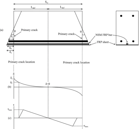
In the multiple crack segmental analysis, the length of primary crack is first determined, allowing the area of analysis to be reduced to half of the primary crack length, Ldef as shown in Figure 1(a) due to the symmetry of forces
θ. The reinforcements slip by δr, δb and δs for the steel bar, FRP bar, and FRP sheet respectively. The slips are
grad-ually reduced the further away from the crack face due to the transfer of load from the steel and FRP reinforcements to the adjacent concrete through bond stress. A numerical analysis is then performed to determine the value of loads Pr, Pb, and Ps that causes these slips by applying the boundary condition of slip being reduced to zero at the
centre of the beam section, as shown in Figure 1(b). With regard to the FRP sheet, a bilinear bond stress-slip such as the one proposed by Lu et al. (2005) is usually applied. In the bilinear model, as shown in Figure 2, the bond stress is reduced to zero at δf. This loss of bond allows the multiple crack segmental analysis to simulate IC
debond-ing (Darain et al., 2016). As shown in Figure 1(b) and Figure 1(c), when the slip for FRP sheet is increased higher than δf, the bond stress is reduced to zero and the area is considered to have debonded.
Figure 1. Multiple crack segmental analysis (a) RC beam segment; (b) Slip distribution for FRP sheet; (c) Bond stress distribution for FRP sheet.
The multiple crack segmental analysis allows for an accurate simulation of tension stiffening in hybrid strengthened RC beams. However, the resulting equilibrium of forces in the multiple crack segmental analysis does not limit the force in the FRP strengthening reinforcements (Oehlers et al., 2015). This greatly affects the accuracy of the simulation as the loss of strength due to IC debonding is not taken into account; this was reflected in the simulated results of Darain et al. (2016), where multiple crack analysis was applied and the simulated results over-predict most of the ultimate load. In response to this, in this paper, a single crack segmental analysis will be used to form a tension stiffening simulation for the FRP sheets and bars.
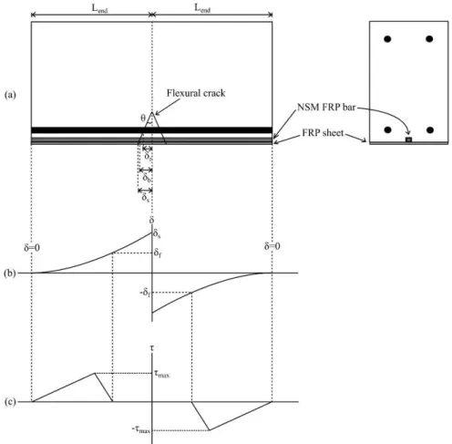
The single crack segmental analysis is focused on the flexural crack forming in the maximum moment region, as shown in Figure 3(a). The load applied to the beam causes a rotation θ which in turn causes slips δr, δb and δs for
the steel bar, FRP bar, and FRP sheet respectively. Numerical analysis is then applied to determine the values of loads Pr, Pb, and Ps that causes these slips. The single crack segmental analysis does not limit the tension stiffening
analysis to half-crack length Ldef; the numerical analysis is continued until the slip is reduced to zero at Lend, which
can be any distance from the crack face. When a slip of FRP sheet is higher than δf, the bond stress is reduced to
zero, as shown in Figure 3(b) and Figure 3(c). Unlike in the multiple crack analysis, the equilibrium of forces in the single crack analysis causes the debonded section to occur while the applied load on the FRP sheet remains constant at PIC, which is the load at which IC debonding starts occurring.
Figure 3. Single crack segmental analysis (a) RC beam segment; (b) Slip distribution for FRP sheet; (c) Bond stress dis-tribution for FRP sheet.
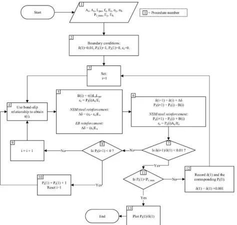
The numerical procedure required for the single crack analysis is as shown below, along with a flowchart in Figure 4:
1. The beam geometry and material properties are determined: a. Area of EB/NSM/steel reinforcement, Ar.
b. Area of concrete adjacent to the EB/NSM/steel reinforcement, Ac. More information on determining the Ac is available elsewhere
(Darain et al., 2016; Shukri et al., 2015; Shukri and Jumaat, 2016). c. Perimeter of EB/NSM/steel reinforcement, Lper.
d. Compressive strength of concrete, fc.
f. Yield strength of steel reinforcement, σy.
g. Ultimate strength of EB/NSM/steel reinforcement, σf.
h. Ultimate load of EB/NSM/steel reinforcement, Pr_max=Arσf
i. Elastic modulus of EB/NSM/steel reinforcement, Ey.
j. Strain hardening modulus of steel reinforcement, Eh.
2. The beam is divided into small segments where the length, Ls=0.1mm. The analysis will start at the crack face, with the following
boundary conditions:
a. Slip of reinforcement, Δr = δ(1) = 0.01 mm.
b. Pc(1) = 0
c. The value of Pr(1) is assumed.
3. The rest of the procedure will determine the forces and strains acting on each beam segment; a dummy variable ‘i’ is introduced to identify the beam segment being solved.
4. The bond stress, τ(i) acting on the EB/NSM/steel reinforcement is determined.
5. The bond force is determined as B(i) = τ(i)LsLper. The strain of the EB/NSM/steel reinforcement is determined as εr = Pr(i)Ar/Er. The
change in slip for the reinforcement from this beam segment to the next segment is determined as ∆δ = (εr − εc)Ls. It should be
noted that for the EB reinforcements, it is assumed that the area of concrete is thin enough to be negligible; the change in slip is thus ∆δ = εrLs.
6. The values of boundary conditions for the next beam segment are determined. Note that the values of Pc(i + 1) and εc are only calculated
for NSM/steel reinforcements: a. δ(i + 1) = δ(i) + ∆δ
b. Pr(i + 1) = Pr(i) − B(i)
c. Pc(i + 1) = Pc(i) + B(i)
d. εc = Pc(i + 1)Ac/Ec
7. The condition δ(i + 1)/δ(1) < 0.01, which represents a 99% reduction from δ(1) is checked. 8. If the condition in procedure 7 is not met, another condition is checked, which is Pr(i + 1) < 0.
9. If the condition in procedure 8 is also not met, the analysis will move on to the next beam segment. The dummy variable i is updated by 1 and procedure 3–8 is repeated.
10. If the condition in procedure 8 is met, the assumed value of applied load Pr(1) is too low and the procedure 2–7 will be repeated with a
higher value of assumed Pr(1).
11. If Pr(1)>Pr_max, the EB/NSM/steel reinforcement has fractured and failed.
12. If condition 11 is not met, the slip δ(1) and the corresponding Pr(1) is then recorded and a larger value of δ(1) is set. The analysis is then
repeated starting from procedure 3.
13. If condition 11 is met, the analysis can be stopped and the load-slip (Pr(1)/δ(1)) relationship is recorded.
The numerical procedure for multiple crack analysis is not presented here, however the full procedure can be found in Shukri and Jumaat (2016).
3 MOMENT-ROTATION SIMULATION
The M/θ simulation is performed within the range of length Ldef, which is determined using the tension
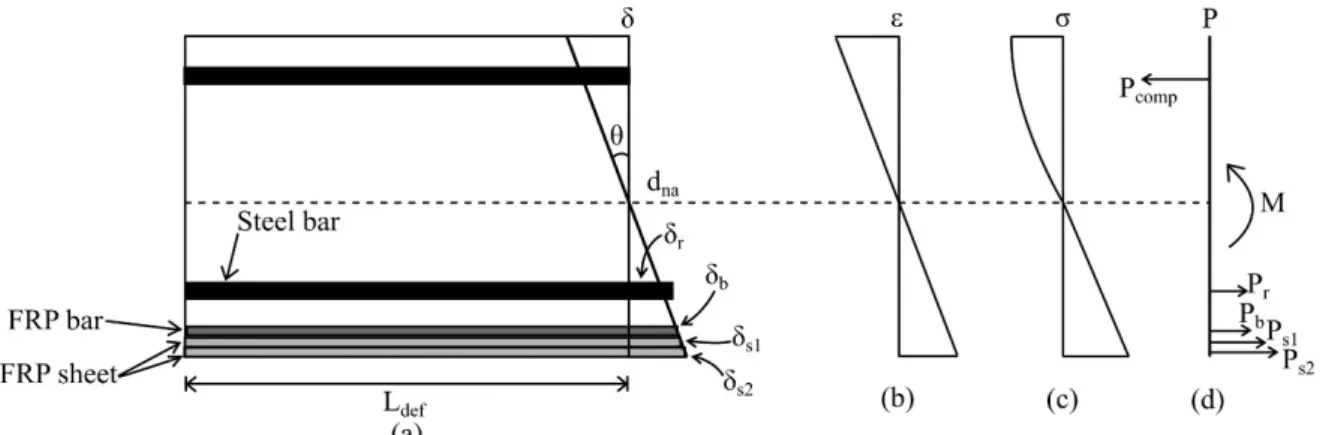
stiff-ening simulation (Shukri and Jumaat, 2016). Consider Figure 4, where a beam section of length Ldef is rotated by θ
degree due to moment M. Prior to flexural cracking, the forces that cause deformation on the beam as shown in Figure 5(a) can be determined from the stress-strain relationships of each material. The depth of neutral axis dna is
then adjusted until equilibrium of forces is achieved; the actual value of moment M which causes rotation θ is then determined.
Figure 5. Moment-rotation analysis (a) Beam segment and deformation profile; (b) Strain profile; (c) Stress profile; (d) Force profile.
When flexural cracking occurs, a slip of reinforcements occurs such that the strains of reinforcement are no longer constant along length Ldef. The forces acting on the steel and FRP reinforcements must then be determined
using the load-slip (Pr/δr) relationship obtained from the tension stiffening simulation, where the slip is determined
from the deformation profile in Figure 5(a). It should be noted that where more than one FRP sheet is used, the slip and the resulting load for each slip must be determined separately as shown in Figure 5(a) and Figure 5(d). The neutral axis dna is then adjusted to obtain the equilibrium of forces and the actual value of is determined. The
pro-cess is repeated for different values of θ in order to obtain an M/θ relationship. The moment-curvature can be obtained by dividing the values of θ with Ldef. The load-deflection relationship of hybrid strengthened RC beams
can then be determined using the commonly used double integration method.
4 VALIDATION OF PROPOSED METHOD
The proposed method was validated against the published experimental results of Darain et al. (2016). The experimental results are from four RC beams strengthened with the hybrid method made up of carbon FRP (CFRP) bars and CFRP sheets. A single CFRP bar was used for each beam, with a diameter of either 8mm or 10mm; the size of the NSM groove on the beam is twice the diameter of the bar used. The beams used either a single or two plies of CFRP sheets used had 0.17mm thickness. Further details on the beams and the materials used are given in Table 1 and Table 2.
Table 1: Beam details.
Beam Designation EB reinforcement NSM reinforcement
CBC8P1 One ply of CFRP sheet One 8 mm CFRP bar
CBC8P2 Two ply of CFRP sheet One 8 mm CFRP bar
CBC10P1 One ply of CFRP sheet One 10 mm CFRP bar
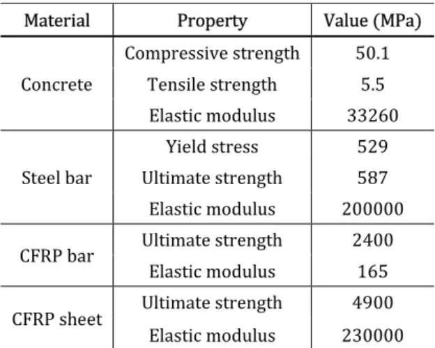
Table 2: Material properties.
Material Property Value (MPa)
Concrete
Compressive strength 50.1
Tensile strength 5.5
Elastic modulus 33260
Steel bar
Yield stress 529
Ultimate strength 587
Elastic modulus 200000
CFRP bar Ultimate strength 2400
Elastic modulus 165
CFRP sheet Ultimate strength 4900
Elastic modulus 230000
5 MATERIAL MODELS
Several material models were used in this paper, which will be mentioned only in brief to keep the paper short. Further details on the material models can be found in the reference given. The material models are only used as input for the tension stiffening and moment-rotation simulations; they can be replaced with other models if deemed appropriate (Knight et al., 2014a).
A bilinear stress-strain relationship with strain hardening was used for the steel reinforcements, while a linear stress-strain relationship was used for the CFRP bars. For the tension stiffening simulation, the bond-slip model by CEB-FIP (1993) was used for the steel reinforcement while the bond-slip model by De Lorenzis (2004) was used to determine the bond force of the NSM reinforcement. The maximum bond stress, τmax was obtained using the
bond strength model by Hassan and Rizkalla (2004). For the tension stiffening analysis of FRP sheet, the bilinear bond-slip model by Lu et al. (2005) was used. For concrete in compression, the stress-strain model by Popovics (1973) was used in conjunction with the size-dependent stress-strain method by Chen et al. (2014).
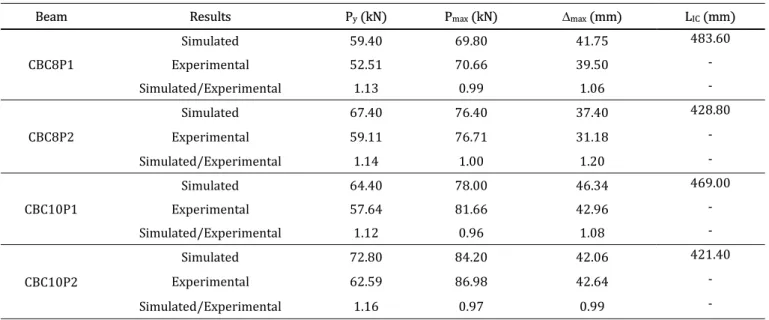
6 COMPARISONS OF SIMULATED AND EXPERIMENTAL RESULTS
Table 3: Summary of simulated and experimental results
Beam Results Py (kN) Pmax (kN) ∆max (mm) LIC (mm)
CBC8P1
Simulated 59.40 69.80 41.75 483.60
Experimental 52.51 70.66 39.50 -
Simulated/Experimental 1.13 0.99 1.06 -
CBC8P2
Simulated 67.40 76.40 37.40 428.80
Experimental 59.11 76.71 31.18 -
Simulated/Experimental 1.14 1.00 1.20 -
CBC10P1
Simulated 64.40 78.00 46.34 469.00
Experimental 57.64 81.66 42.96 -
Simulated/Experimental 1.12 0.96 1.08 -
CBC10P2
Simulated 72.80 84.20 42.06 421.40
Experimental 62.59 86.98 42.64 -
Simulated/Experimental 1.16 0.97 0.99 -
Note: Py=yield load; Pmax=maximum load; ∆max=deflection at maximum load; LIC=length of IC debonding.
A comparison between simulated and experimental load-deflection results are also given in Figure 6. The sim-ulated load-deflection using the method proposed Darain et al. (2016) is also included in Figure 6; their simsim-ulated results were obtained using the multiple crack analysis and hence is incapable of simulating IC debonding. Its in-clusion in Figure 6 is meant to show the benefit of simulating IC debonding as opposed to ignoring it. It can be seen that the method proposed in this paper is able to follow the general shape of the experimental load-deflection curve relatively well compared to the simulation using the method by Darain et al. (2016) which tends to overpredict the load-deflection capacity of hybrid strengthened RC beams, especially after steel yielding. However, the previous simulation method by Darain et al. (2016) was found to be better at predicting the pre-yield stiffness of the beams, which as mentioned before can be attributed to the multiple crack analysis being better at simulating tension stiff-ening (Oehlers et al., 2015). However, the new method proposed in this paper is better at predicting the failure load of the hybrid strengthened beams.
7 PARAMETRIC STUDY
The proposed simulation method was used to perform several parametric studies. The details of the simulated beams used for the parametric study is similar to beam CBC10P1, apart from the list of properties listed in Table 4. Four test groups were used for the parametric studies. Test groups n-e and s-e were used to study the effect of the elastic modulus of NSM FRP bars (Er-nsm) and FRP sheets (Er-sheet) respectively; test groups n-t and s-t, on the other
hand, were used to determine the effect of the bond strength of NSM FRP bars (τmax-nsm) and FRP sheets (τmax-sheet)
respectively.
Table 4: Properties of simulated hybrid strengthened RC beams.
Test Group Beam Er-nsm (GPa) Er-sheet (GPa) τmax-nsm (GPa) τmax-sheet (GPa)
n-e
n-e-50 50 230 9.31 6.78
n-e-100 100 230 9.31 6.78
n-e-150 150 230 9.31 6.78
n-e-200 200 230 9.31 6.78
s-e
s-e-50 165 50 9.31 6.78
s-e-100 165 100 9.31 6.78
s-e-150 165 150 9.31 6.78
s-e-200 165 200 9.31 6.78
n-t
n-t-5 165 230 5 6.78
n-t-10 165 230 10 6.78
n-t-15 165 230 15 6.78
n-t-20 165 230 20 6.78
s-t
s-t-5 165 230 9.31 5
s-t-10 165 230 9.31 10
s-t-15 165 230 9.31 15
s-t-20 165 230 9.31 20
Note: Er-nsm=elastic modulus of NSM FRP bar; Er-sheet=elastic modulus of FRP sheet; τmax-nsm=bond strength of NSM FRP bar; τmax-sheet=bond strength of
FRP sheet.
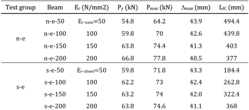
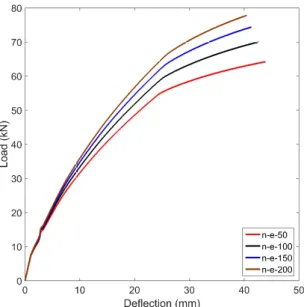
The summary of the simulated results for test groups n-e and s-e is given in Table 5, while Figure 7 and Figure 8 shows the load-deflection results for test group n-e and s-e respectively. All the beams failed through concrete crushing, which in this paper is taken as the concrete strain of 0.003. The yield load (Py) and maximum load (Pmax)
of the hybrid strengthened beams were found to increase as the values of Er-nsm and Er-sheet are increased.
Table 5: Summary of simulated results for test group n-e and s-e
Test group Beam Er (N/mm2) Py (kN) Pmax (kN) ∆max (mm) LIC (mm)
n-e
n-e-50 Er-nsm=50 54.8 64.2 43.9 494.4
n-e-100 100 59.8 70 42.6 439.8
n-e-150 150 63.8 74.4 41.3 403
n-e-200 200 66.8 77.8 40.5 377
s-e
s-e-50 Er-sheet=50 59.8 71.8 43.3 184.4
s-e-100 100 62.2 73 42.4 262.8
s-e-150 150 63.2 74 42.0 322.4
s-e-200 200 63.8 74.6 41.1 368
Figure 7. Load-deflection results of test group n-e.
Figure 8. Load-deflection results of test group s-e.
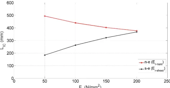
In Figure 9, a plot of Er against the length of IC debonding, LIC is presented. It should be noted that the value of
Er for test group n-e and s-e refer to Er-nsm and Er-sheet respectively. The LIC was found to decrease when higher E r-nsm was used. On the other hand, as the Er-sheet is increased, the LIC also increases. This contrasting IC debonding
behaviour inevitably affects the load-deflection relationships of the beams as well. As shown in Figure 7, since the LIC decreases for higher Er-nsm, a significant increase in the stiffness and maximum load for beams in test group n-e
Figure 9. Comparison of simulated IC debonding length for test group n-e and s-e.
A summary of the results for test groups n-t and s-t is given in Table 6; the load-deflection results are shown in Figure 10 and Figure 11. Similar to before, all beams failed by concrete crushing. From Table 6, it can be seen that higher values of τmax-nsm and τmax-sheet causes the Py and Pmax to increase. However, the overall increase is much
lower when compared to the increase seen in the parametric study of elastic modulus, which suggests that while
τmax-nsm and τmax-sheet are important for tension stiffening, changes in their values does not impact the behaviour of
hybrid strengthened beams to a significant degree.
Table 6: Summary of simulated results for test group n-t and s-t
Test group Beam τmax (N/mm2) Py (kN) Pmax (kN) ∆max (mm) LIC (mm)
n-t
n-t-5 τmax-nsm=5 62.2 74 41.9 395.6
n-t-10 10 64.6 75.4 41.0 395.6
n-t-15 15 66.8 76.4 39.6 384.4
n-t-20 20 68.8 77.4 38.5 377
s-t
s-t-5 τmax-sheet=5 65.4 75.2 41.3 376.6
s-t-10 10 65.6 75.2 41.1 412.8
s-t-15 15 66.2 76.2 40.4 346.6
s-t-20 20 67.2 77.2 39.5 298.6
Note: τmax=bond strength; τmax-nsm=bond strength of NSM FRP bar; τmax-sheet=bond strength of FRP sheet; Py=yield load; Pmax=maximum load; ∆max=deflection at maximum load; LIC=length of IC debonding.
Figure 11. Load-deflection results of test group s-t.
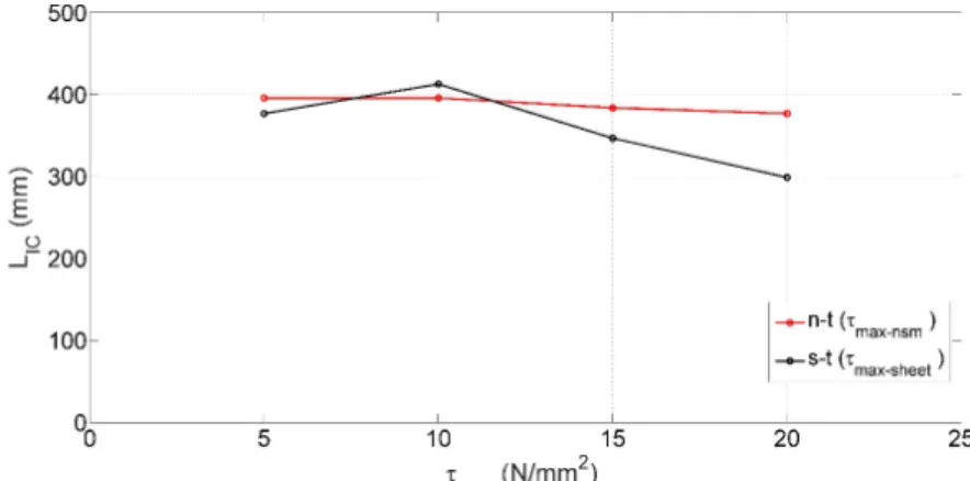
A plot of LIC against τmax for test group n-t and s-t is given in Figure 12. The LIC was found to reduce for higher
values of τmax-nsm. The result of LIC-τmax-sheet curve shows a similar trend, apart from a slight increase in LIC for beam
s-t-10, which uses τmax-sheet = 10 N/mm2. This slight increase in LIC is related to the bond stress and slip of the FRP
sheet. Consider Figure 13(b) and Figure 13(c), which shows the slip and bond stress distribution of the FRP sheet for beams s-t-5, s-t-10 and s-t-15. At the same amount of initial slip δ1, the beam with a higher τmax-sheet such as beam
s-t-15 will have a shorter hinge span (Lend) due to a quicker transfer of force from the FRP sheet to the concrete.
However, the transfer of force for beam s-t-10 is not high enough; this causes beam s-t-5 and s-t-10 to have an almost similar Lend. As the Lend is the same, the summation of bond stresses τsum for both beams should be similar.
However, beam s-t-10 have a higher τmax-sheet than beam s-t-5. This results in beam s-t-10 having a longer LIC in
order to have the same τsum as beam s-t-5. This situation does not occur in beam s-t-15, which have a high enough
τmax-sheet to cause it to have a significantly shorter Lend compared to the other two beams. The LIC for beam s-t-15 is
also the shortest of the three beams. The most significant effect of a longer LIC is the reduction of the strength and
stiffness for beam s-t-10. This can be seen in Figure 11, where the load-deflection curve for s-t-5 and s-t-10 is almost identical despite beam s-t-10 having a higher τmax-sheet.
Figure 13. Distribution of slip and bond stress of FRP sheet (a) Beam detail; (b) Bond stress distribution for FRP sheet; (c) Slip distribution for FRP sheet.
8 CONCLUSIONS
An improvement to the method presented by Darain et al. (2016) for simulating the behaviour of hybrid strengthened RC beams was proposed, which can correctly simulate the effect of IC debonding. Several conclusions were made based on the work done:
• The proposed method was able to simulate the behaviour of hybrid strengthened beams with good accuracy. The single crack analysis was found to be important in simulating the loss of stiffness due to IC debonding in hybrid strengthened RC beams.
• The simulated maximum load was found to be within 4% of the experimental value.
• On the other hand, the simulated maximum deflection was found to be less accurate with deviation from the experimental value from 1% to 20%.
• The simulated yield load was found to deviate from experimental values from 12-16% due to the use of the single crack analysis as the basis of the tension stiffening simulation, as the single crack analysis is known to be less accurate at predicting tension stiffening effect compared to the multiple crack analysis.
• Increasing the elastic modulus of NSM FRP bar increases the stiffness and maximum load of the hybrid strengthened beam while decreasing the length of IC debonding.
• Increasing the elastic modulus of FRP sheet, on the other hand, increases the length of IC debonding; as such while the stiffness and maximum load of the hybrid strengthened beam still increase, the amount is less significant compared to increasing the elastic modulus of NSM FRP bar.
• Increasing the bond strength of NSM FRP bar and FRP sheet slightly increases the stiffness and maximum load of hybrid strengthened beams.
While the proposed method is perhaps too complicated to be used in general design, it is hoped that it can be used to perform further studies on the hybrid strengthening method similar to the parametric study presented in this paper. The proposed method should be applicable to hybrid strengthened beams using any type of material and shape of FRP reinforcement, assuming the correct material models (in particular the bond stress-slip model) are used.
Acknowledgement
This study was funded by the University of Malaya, Grand Challenge - SUS (Sustainability Science) Grant, pro-ject number GC003A-15SUS.
References
Badawi M and Soudki K (2009) Flexural strengthening of RC beams with prestressed NSM CFRP rods - Experi-mental and analytical investigation. Construction and Building Materials 23(10): 3292–3300.
slabs according to a new hybrid technique using U-shape CFRP laminates. Composite Structures 159: 600–614.
Capozucca R and Magagnini E (2016) Vibration of RC beams with NSM CFRP with unbonded/notched circular rod damage. Composite Structures 144: 108–130.
Capozucca R, Domizi J and Magagnini E (2016) Damaged RC beams strengthened with NSM CFRP rectangular rods under vibration in different constrain conditions. Composite Structures 154: 660–683.
CEB-FIP (1993) CEB-FIP model code 1990. London, UK: Thomas Telford Ltd.
Ceroni F, Pecce M, Matthys S, et al. (2008) Debonding strength and anchorage devices for reinforced concrete ele-ments strengthened with FRP sheets. Composites Part B: Engineering 39(3): 429–441.
Chen GM, Zhang Z, Li YL, et al. (2016) T-section RC beams shear-strengthened with anchored CFRP U-strips. Com-posite Structures 144: 57–79.
Chen Y, Visintin P, Oehlers D, et al. (2014) Size-Dependent Stress-Strain Model for Unconfined Concrete. Journal of Structural Engineering 140(4): 4013088.
Darain KM ud, Jumaat M, Shukri AA, et al. (2016) Strengthening of RC Beams Using Externally Bonded Reinforce-ment Combined with Near-Surface Mounted Technique. Polymers 8(7): 261.
De Lorenzis L (2004) Anchorage length of near-surface mounted fiber-reinforced polymer rods for concrete strengthening - Analytical modeling. ACI Structural Journal 101(3): 375–386.
Fabrics H, Cedex V, Cedex R, et al. (2003) Experimental analysis of flexural behaviour of externally bonded CFRP reinforced concrete structures. 36(May): 238–241.
Gupta AK and Maestrini SR (1990) Tension Stiffness Model for Reinforced Concrete Bars. Journal of Structural En-gineering 116(3): 769-790.
Haskett M, Oehlers DJ and Mohamed Ali MS (2008) Local and global bond characteristics of steel reinforcing bars. Engineering Structures 30(2): 376–383.
Hassan TK and Rizkalla SH (2004) Bond mechanism of near-surface-mounted fiber-reinforced polymer bars for flexural strengthening of concrete structures. ACI Structural Journal 101(6): 830–839.
Knight D, Visintin P, Oehlers DJ, et al. (2014a) Short-Term Partial-Interaction Behavior of RC Beams with Pre-stressed FRP and Steel. Journal of Composites for Construction 18(1): 4013029.
Knight D, Visintin Phillip, Oehlers DJ, et al. (2014b) Simulating RC beams with unbonded FRP and steel prestressing tendons. Composites Part B: Engineering 60: 392–399.
Kreit A, Al-Mahmoud F, Castel A, et al. (2011) Repairing corroded RC beam with near-surface mounted CFRP rods. Materials and Structures 44(7): 1205–1217.
Lu XZ, Teng JG, Ye LP, et al. (2005) Bond-slip models for FRP sheets/plates bonded to concrete. Engineering Struc-tures 27(6): 920–937.
Maalej M (2005) Analysis and design of FRP externally-reinforced concrete beams against debonding-type failures. Materials and Structures 34(241): 418–425.
Narayanamurthy V, Chen JF, Cairns J, et al. (2012) Plate end debonding in the constant bending moment zone of plated beams. Composites Part B: Engineering 43(8): 3361–3373.
Oehlers D, Visintin P, Zhang T, et al. (2012) Flexural rigidity of reinforced concrete members using a deformation based analysis. Concrete in Australia 38(4): 50–56.
Oehlers DJ, Visintin P, Haskett M, et al. (2013) Flexural ductility fundamental mechanisms governing all RC mem-bers in particular FRP RC. Construction and Building Materials 49: 985–997.
Oehlers DJ, Visintin P and Lucas W (2015) Flexural Strength and Ductility of FRP-Plated RC Beams: Fundamental Mechanics Incorporating Local and Global IC Debonding. Journal of Composites for Construction 20(2): 4015046.
Pachalla SKS and Prakash SS (2017) Efficient near surface mounting CFRP strengthening of pretensioned hollow-core slabs with opening – An experimental study. Composite Structures, Elsevier Ltd 162: 28–38.
Pesic N (2005) Flexural analysis and design of reinforced concrete beams with externally bonded FRP reinforce-ment. Materials and Structures 38(276): 183–192.
Popovics S (1973) A numerical approach to the complete stress-strain curve of concrete. Cement and Concrete Research 3(5): 583–599.
Rahman M, Jumaat MZ, Rahman MA, et al. (2015) Innovative hybrid bonding method for strengthening reinforced concrete beam in flexure. Construction and Building Materials, Elsevier Ltd 79: 370–378.
Seo S, Sung M and Feo L (2016) Flexural analysis of RC beam strengthened by partially de-bonded NSM FRP strip. Composites Part B, Elsevier Ltd 101: 21–30.
Shukri AA and Jumaat MZ (2016) Simulating concrete cover separation in RC beams strengthened with near-sur-face mounted reinforcements. Construction and Building Materials 122: 1–11.
Shukri AA, Darain KM ud and Jumaat MZ (2015) The Tension-Stiffening Contribution of NSM CFRP to the Behavior of Strengthened RC Beams. Materials 8(7): 4131–4146.
Shukri AA, Hosen MA, Muhamad R, et al. (2016) Behaviour of precracked RC beams strengthened using the side-NSM technique. Construction and Building Materials 123: 617–626.
Tam B, Si A and Limam A (2016) Numerical modelling of reinforced concrete beams repaired by TRC composites. Composite Structures 152: 779–790.
Toutanji H, Zhao L and Zhang Y (2006) Flexural behavior of reinforced concrete beams externally strengthened with CFRP sheets bonded with an inorganic matrix. Engineering Structures 28(4): 557–566.
Visintin P, Oehlers DJ, Wu C., et al. (2012a) A mechanics solution for hinges in RC beams with multiple cracks. En-gineering Structures 36: 61–69.
Visintin P, Oehlers DJ, Wu Chengwing, et al. (2012b) The reinforcement contribution to the cyclic behaviour of re-inforced concrete beam hinges. Earthquake Engineering & Structural Dynamics 41: 1591–1608.
Visintin P, Oehlers DJ, Muhamad R, et al. (2013a) Partial-interaction short term serviceability deflection of RC beams. Engineering Structures 56: 993–1006.