About the use of semi-continuity to remove fireproof
coatings in simply supported composite steel and
concrete beams
Sobre o aproveitamento da semicontinuidade para
eliminar o revestimento contra fogo em vigas mistas de
aço e concreto biapoiadas
a Escola Politécnica da Universidade de São Paulo, SP, Brasil.
Received: 10 Nov 2016 • Accepted: 04 Jul 2017 • Available Online: 9 Apr 2018
L. C. ROMAGNOLI a
lucas.romagnoli@usp.br
V. P. SILVA a
valpigss@usp.br
Abstract
Resumo
The behavior under fire conditions of composite steel and concrete beams, not subjected to local buckling (compact steel profile), was studied con
-sidering the support rotational stiffness provided by the upper longitudinal slab reinforcement, usually present by means of anti-cracking meshes, and restriction of the steel profile’s lower flange, additional procedure required for development of the support bending moment resistance. Usu
-ally composite beams at room temperature are designed as simply supported and the semi-rigidity provided by this longitudinal reinforcement, if considered under fire conditions, may lead to a lower cost solution for fire protection of composite beams. The purpose of this study is to verify the viability of this proposal, using simplified design code methods.
Keywords: fire, composite steel concrete beam, semi-continuous.
Estudou-se o comportamento sob ação do incêndio de vigas mistas de aço e concreto, sem instabilidades locais (ditas compactas), considerando
a rigidez à flexão nos apoios fornecida pela armadura negativa longitudinal à viga, usualmente presente por meio de malhas antifissuração, e restrição da mesa inferior do perfil de aço, procedimento adicional necessário para desenvolvimento do momento fletor resistente no apoio. Ge -ralmente as vigas mistas são dimensionadas à temperatura ambiente como biapoiadas e a semicontinuidade proporcionada por essa armadura longitudinal, se considerada em situação de incêndio, pode conduzir a uma solução de menor custo para proteção contra fogo das vigas mistas.
O objetivo deste trabalho é verificar a viabilidade dessa proposta, usando métodos normativos simplificados.
1. Introduction
1.1 Objective
A simply supported composite steel and concrete beam designed at room temperature, when analyzed in a fire situation according to ABNT NBR 14323 [1] procedures, generally does not have suf
-ficient structural safety unless fireproof coatings are present. Such
solution is responsible for raising costs related to the choice of the
composite structural system.
The objective of this study is to evaluate the behavior of composite steel and concrete beams in fire situation, taking in consideration the rotational stiffness of the supports provided by the upper lon
-gitudinal reinforcement present in the concrete slab and by the re
-striction of the steel profile’s lower flange in the support, creating a composite connection as shown in Figure 1 and ensuring a
semi-continuous behavior to the beam. The beam structural capacity increase provided by the adoption of this solution may be sufficient as a low cost alternative when compared to the application of fire
-proof coatings. For validity of the proposed method it is assumed
that the main supporting beam, connecting plates and angles and
bolts receive fireproof coating.
In a steel profile under a concrete slab its faces are not exposed equally by the fire since the slab provides a protection to the upper flange, leading to a non-uniform distribution of the internal temper -ature. This thermal gradient along the cross section height causes
additional deformations and, in case of hyper-static structures, in -direct stresses due to the supports rotation restriction. Figure 2
illustrates this phenomenon. If the structure is already subjected to negative bending moments at the support, they may be amplified during fire exposure.
At first, this harmful effect will be neglected in use of a simplified method and evaluated in the future by non-linear thermal structural numerical analysis.
1.2 Background
The benefits of composite steel and concrete construction fire re
-sistance in a building, when compared to the isolated steel element analyzed in laboratory, has been the subject of studies by several authors. Based on the Cardington test, where the capacity of the composite structure was verified to be greater in comparison to the design codes recommendations, Usmani et al., 2001 [2, 3], observed the possibility of reducing fireproof coatings for this type of structural system. With aid of numerical analysis it was pointed out that the large deformations caused by the degradation of the steel’s elastic modulus are responsible for inducing tension stress -es on the steel beam and concrete slab, creating a membrane
ef-fect capable of resisting gravitational actions. Recent studies by Kodur et al., [4], show how beneficial it may be to consider such effect on slab panels over beams without fireproof coating, reach
-ing 60 and 90 minute fire resistance times. Huang et al., 2015 [5],
emphasize the role of reinforcement steel meshes in the concrete slab to resist membrane stresses. Design code methods do not
consider such effect that can be better evaluated with numerical modeling, as concluded by Wang et al., 2012 [6] when comparing numerical analysis results of an asymmetric composite beam with
-out fireproof coating with the Eurocode recommendations. With consideration of the membrane effect the formation of plastic hinges is no longer the beam ultimate limit state, which explains the large differences between numerical models and design codes
recommendations. Chiou et al., 2009 [7], conclude that the axial
restriction of the beam is sufficient to mobilize tensile stresses, but alert for large permanent deformations in the floor, which do not recover during the cooling phase. The beam’s shear force capacity should also be carefully analyzed because according to Kodur and Naser, 2015 [8], in some cases such capacity can degrade more rapidly compared to the bending moment during fire.
Nguyen and Tan, 2015 [9], point out that boundary conditions play
Figure 1
an important role in the mobilization of the membrane effect, con
-cluding that the stiffness of the fireproof coated main beams sup
-porting the secondary floor beams has a direct influence on the collapse time. Huang et al., 2015 [5] present similar results, also alerting to the influence of the main beam-column connections. The consideration of semicontinuity in the analysis of composite beams in a fire has already been proposed by Ioannides and Mehta, 1997 [10] who adopted as methodology the determination of the beam’s cross section plastic hinge capacity in the middle of the span and at the supports and concluded, in the case of a fireproof coated beam, that there is a relevant gain in its load capacity. Fakury et al., 2005 [11], compared simply supported and semi-continuous fire -proof coated composite beams capacities, using the Eurocode
de-sign method, and detected a capacity gain of 116% to 123%. Fischer and Varma, 2017 [12], performed a numerical analysis of fireproof coated composite beams supported by simple shear connections
(single plate, single angle and double angle), concluding that the
slab continuity at the supports and presence of reinforcement steel meshes have great influence on the behavior of the beam during fire
and the collapse did not occur due to connections failure.
1.3 Problem analysis
The study was carried for several cross sections, covering the va
-riety of Gerdau brand profiles and 8 to 18 cm slab thicknesses.
Following the recommendation of ABNT NBR 8800 [13] O.2.4.1.1, adjusted for fire situation as suggested by ABNT NBR 14323 [1] by reducing slenderness parameters by 0.85 of its room temperature values, some profiles classified as slender, that is, with a flange width and thickness ratio greater than , were not consid
-ered in the analysis. The compressive strength of the concrete was assumed 30 MPa and the steel yield strength 345 MPa.
The distortional buckling that may occur in the negative bending moment regions of composite beams was not considered. There -fore, for direct use of the presented results, it must be ensured that the λdist parameter, determined according to ABNT NBR 8800 [13] O.2.5.2, is higher than 0.4. ABNT NBR 14323 [1] does not provide
specific recommendations for distortional buckling of composite beams in fire, but in case of cold formed profiles it is advised λdist
to be calculated as at room temperature, however with a more se
-vere high temperature steel’s reduction factor than the one used in profiles not subjected to local or distortional buckling. Such factor
is found in [1].
The effective width of the concrete slab was 2 m for all cases. The slab reinforcement ratio was such that it allowed the develop -ment of the maximum negative bending mo-ment resistance, as explained in chapter 5. The number of shear connectors was the
required for full iteration at room temperature.
The fire resistant strength of the beams was evaluated, assum
-ing a standard fire resistance requirement of 30 minutes for the
Figure 2
simply supported and semi-continuous condition, and the values were compared to those at room temperature design.
The standard fire resistance requirement of 30 min was chosen because it is a low value and, therefore, more likely to lead to fa -vorable results.
2. Structural elements temperature
In the calculation of the resistant capacity of composite steel and
concrete sections a non-uniform temperature distribution at the height of the cross-section is considered. The recommendation of ABNT NBR 14323 [1] is to divide the composite section into each
of its components: the concrete slab and the steel profile upper and lower flanges and web. It is assumed that there is no heat transfer between these parts.
In the steel elements, the temperature increase of each
compo-nent is determined considering the massivity factor calculated for each element alone, according to the simplified method recom
-mended by ABNT NBR 14323 [1] 8.5.1.1. In security favor, the shading factor will be considered equal to 1, following one of ABNT
NBR 14323 [1] alternatives.
To evaluate the temperature at which the composite beam con
-crete slab is subjected during fire, the recommendation of ABNT
NBR 14323 [1] is to divide the height of the slab in 14 slices and
assign a temperature for each range according to the standard fire resistance requirement (Table 1).
3. Shear connectors
ABNT NBR 14323 [1] recommends the strength of a shear
con-nector to be determined in the same way as ABNT NBR 8800 [13], taking into consideration, however, reduction factors of unity and
concrete compressive strength and elastic modulus reduced by
,θ
c
k
at a temperature equivalent to 40% of the steel profile upper flange temperature. The shear connector ultimate tensile strength should also be reduced by 0.80k
y,θ for a temperature equivalentto 80% of the temperature of the steel profile upper flange. Equation (1) is already adjusted for fire situation.
(1)
In Equation (1):
Qfi,Rd is the shear connector strength in fire situation; Acs is the shear connector cross-section area;
kc,θ is the concrete reduction factor;
ky,θ is the steel reduction factor; fck is the concrete compressive strength; fucs is the steel ultimate tensile strength; Ecs is the concrete elastic modulus;
Rg is the factor used for consideration of a group of shear
con-nectors;
Rp is the factor used for consideration of shear connector position.
4. Positive bending moment resistance
The design procedure described by ABNT NBR 14323 [1] is lim -ited to recommendations of using the room temperature designsuggested by ABNT NBR 8800 [13] with reduction factors of unity and reducing the concrete compressive strength and steel yield strength by kc,θ and ky,θ coefficients, respectively.
The factor of 0.85 used to determine the maximum compressive
stress in the concrete slab will be assumed as 1.00 according to the recommendation of Bulletin nº 46 fib-CEB, 2008 [14].
Table 1
Concrete slab temperature distribution [ºC] (adapted from ABNT NBR 14323 [1] and EN 1994-1-2 [15])
Slice (y) mmHeight Standard fire resistance requirement (min)
30 60 90 120 180 240
1 0 a 5 535 705 – – – –
2 5 a 10 470 642 738 – – –
3 10 a 15 415 581 681 754 – –
4 15 a 20 350 525 627 697 – –
5 20 a 25 300 469 571 642 738 –
6 25 a 30 250 421 519 591 689 740
7 30 a 35 210 374 473 542 635 700
8 35 a 40 180 327 428 493 590 670
9 40 a 45 160 289 387 454 549 645
10 45 a 50 140 250 345 415 508 550
11 50 a 55 125 200 294 369 469 520
12 55 a 60 110 175 271 342 430 495
13 60 a 80 80 140 220 270 330 395
Given a standard fire resistance requirement, the maximum allowable compressive force in the concrete slab is deter -mined as the sum of the plastic forces of each temperature
slice (Table 1) multiplied by kc,θ factor, according to Equa -tion (2).
(2)
In Equation (2):
b is the slab effective width;
hn is the thickness of the nth slab slice;
kn
c,θ is the reduction factor of the nth slab slice.
The maximum tensile strength which the steel profile can be subjected is the sum of the plastic forces of each element (lower flange, web and upper flange), according to Equation (3).
(3)
The index “w” corresponds to the steel profile web, the index “fs” to the upper flange and “fi” to the lower flange.
When the sum of the resistances in fire situation of the shear connectors located between the section of maximum positive bending moment and the adjacent null bending moment section
is greater than the lower of the values
and a full interaction is characterized, for lower values a partial interaction is characterized.
4.1 Plastic neutral axis on concrete slab
In a full interaction, when , the plastic neutral axis
must be, by equilibrium, in the concrete slab. Thus, the tensile force in the steel profile is given by Equation (4).
(4)
The amount of slab slices to be considered should be such that
the compressive force Ccd,fi is equal to Tad,fi , for this the value
of a (Figure 3), starting from the top of the slab, that satisfies the
Ccd,fi = Tad,fi condition must be found.
The bending moment resistance must be determined by multiply
-ing the plastic forces of each element (lower and upper flanges, web and slab slices) by the C.G. distance of each element to the PNA. Equations (5) to (8) indicate the contribution of each element (parameters according to Figure 4).
(5)
(6)
(7)
(8)
The dn parameter represents the distance from the C.G. of each slab slice under compression to the upper face of the slab, accord-ing to Figure 3.
The bending moment resistance in fire situation is then defined by Equation (9).
(9)
4.2 Plastic neutral axis on steel profile
In full interaction, when the plastic neutral axis is
found on the steel profile. The compressive force in the concrete slab is given by Equation (10).
(10)
The compression force Cad,fi on the steel profile is given by Equa -tion (11) in order to balance the tensile and compression forces in the cross section.
(11)
If the compression force in the steel profile is lower than the plastic
Figure 3
Slab height under compression “a”
(adapted from ABNT NBR 14323 [1])
Figure 4
force of the upper flange, that is , the PNA is located on the upper flange and its position relative to the upper face of the steel profile yp is defined by Equation (12).
(12)
Equations (13) to (16) indicate the contribution of each element
for the bending moment resistance, relative to the PNA. Figure 5 illustrates the position of the plastic neutral axis.
(13)
(14)
(15)
(16)
The dn parameter represents the distance from the C.G. of each
slice under compression to the upper face of the slab, according to Figure 3.
If the plastic neutral axis is located in the steel
profile web and its position relative to the upper face of the steel profile is given by Equation (17).
(17)
Equations (18) to (21) indicate the contribution of each element for
the bending moment resistance, relative to the PNA.
Figure 6 shows the position of the plastic neutral axis.
(18)
(19)
(20)
(21)
The bending moment resistance in fire situation is defined as the sum of each element contribution, according to Equation (9).
4.3 Partial interaction
In case of a partial interaction it is assumed that the greatest
com-pressive force that can be transmitted to the concrete slab will be the maximum strength of the shear connectors, which is described by Equation (22).
(22)
Figure 5
Plastic neutral axis on steel profile upper flange
Figure 6
Plastic neutral axis on steel profile web
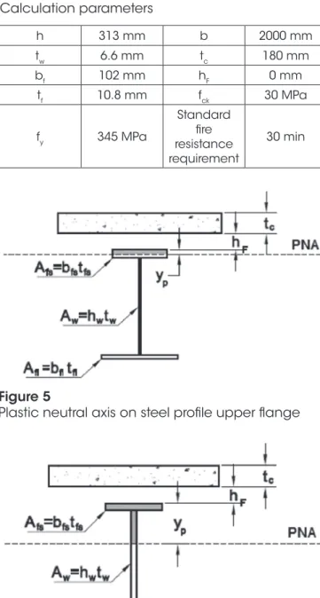
Table 2
Calculation parameters
h 313 mm b 2000 mm
tw 6.6 mm tc 180 mm
bf 102 mm hF 0 mm
tf 10.8 mm fck 30 MPa
fy 345 MPa
Standard fire resistance requirement
30 min
For this reason, the concrete slab is not entirely under compres -sion, the parameter a (Figure 3, although the value will not corre
-spond to the PNA position) is such that the sum of the slices forces
corresponds to ΣQfi,Rd.
Because it is a partial interaction, the strength of the shear
connec-tors is lower than the maximum tensile force which the steel profile can be subjected to, in other words , characterizing the same expressions of Cad,fi and yp defined in 4.2, but the contri-bution to the bending moment resistance of the concrete slab
4.4 Design example
The parameters described in Table 2 represent the design of a
W310x32.7 Gerdau profile under a 18 cm concrete slab, other pa
-rameters are described in 1.3. The calculation of the temperature in each structural element is summarized in Table 3 and Table 4. Table 5 indicates other partial results. Note that for this case the plastic neutral axis is located on the concrete slab.
5. Negative bending moment resistance
ABNT NBR 14323 [1] suggests to neglecting the concrete slab
and the longitudinal reinforcement present in the effective width in sections under negative bending moment, resisting only the steel profile cross section and, of course, resulting in very conservative resistance values. In order to evaluate the effect of the longitudinal reinforcement on the slab near the supports this suggestion will not be followed, and the negative bending moment resistance will be
determined according to the general recommendation of
EN-1994-1-2 [15], by plasticity theory taking into account the variation of the materials properties by temperature.
ABNT NBR 15200 [16] defines reduction factors lower than 1.00 for CA-50 steel only for temperatures above 400 °C and, noting
Table 1, the upper slices of the concrete slab do not reach that temperature. It is concluded that the reinforcement located near
the top layer of the concrete slab does not suffer a reduction of its capacity even for high values of standard fire resistance require
-ment; in this way the maximum tensile strength allowed in the negative longitudinal reinforcement within the effective width will be the same as in room temperature, determined by Equation (23).
(23)
At Equation (23):
Asl is the total cross sectional area of longitudinal reinforcement
within the slab effective width;
fsd is the reinforcement steel design yield strength at room temperature. If the reinforcement ratio is too high resulting in , the
entire steel profile will be compressed and the bending moment resistance will be the result from the force couple of the reinforce
-ment and the steel profile. In this case, to ensure that the following
formulations do not result in negative values, assume .
The tensile strength of the steel profile is given by Equation
(24) in order to balance the tensile and compression forces in the cross section.
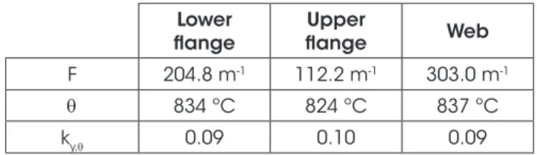
Table 3
Steel elements temperature and reduction factor
Lower flange
Upper
flange Web
F 204.8 m-1 112.2 m-1 303.0 m-1
θ 834 ºC 824 ºC 837 ºC
ky,θ 0.09 0.10 0.09
Table 4
Concrete slab temperature and reduction factor
Slice h θ kc,θ
1 100 mm 60 1.00
2 20 mm 80 1.00
3 5 mm 110 1.00
4 5 mm 125 0.99
5 5 mm 140 0.98
6 5 mm 160 0.97
7 5 mm 180 0.96
8 5 mm 210 0.94
9 5 mm 250 0.90
10 5 mm 300 0.85
11 5 mm 350 0.80
12 5 mm 415 0.73
13 5 mm 470 0.65
14 5 mm 535 0.55
Table 5
Partial results for positive bending moment resistance
10290.8 kN
133.4 kN
0.22 cm
14.8 kN.cm
682.2 kN.cm
2032.3 kN.cm
1717.0 kN.cm
44.5 kN.m
Figure 7
(24)
If the tensile force in the steel profile is lower than the plastic force of the upper flange, that is , the PNA is located on the upper flange and its position relative to the upper face of the steel profile y is defined by Equation (25).
(25)
Equations (26) to (29) indicate the contribution for the bending
mo-ment resistance of each elemo-ment, relative to the PNA.
Figure 7 shows the position of the plastic neutral axis.
(26)
(27)
(28)
(29)
If the plastic neutral axis is located in the steel
profile web and its position relative to the upper face of the steel profile is given by Equation (30).
(30)
Equations (31) to (34) indicate the contribution for the bending
mo-ment resistance of each elemo-ment, relative to the PNA.
Figure 8 shows the position of the plastic neutral axis.
(31)
(32)
(33)
(34)
The bending moment resistance in fire situation is defined as the sum of each element contribution, according to Equation (35).
(35)
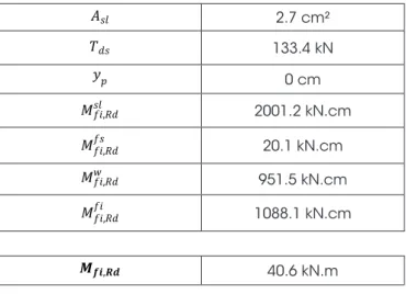
5.1 Design example
Using the parameters already presented in Table 2 and assuming a reinforcement ratio such that , CA-50 reinforcement steel and the distance ds of 15.0 cm, the partial results are pre-sented in Table 6.
Figure 8
Plastic neutral axis on steel profile web, negative
bending moment
Table 6
Partial results for negative bending moment
resistance
2.7 cm²
133.4 kN
0 cm
2001.2 kN.cm
20.1 kN.cm
951.5 kN.cm
1088.1 kN.cm
40.6 kN.m
6. Beam plastic capacity
It is known from the plastic analysis of a fixed beam that the maxi
-mum value of the bending moment in the center of the span will be equal to the cross section positive plastification moment and, in the supports, equal to the cross section negative plastification moment. To achieve equilibrium the sum of these two bending mo
-ments must be equal to pL²/8.
The maximum distributed load to which the beam can be subject -ed, before the formation of the plastic hinges in the support and
center span, is described by Equation (36);
(36)
The plastic capacity of the semi-continuous composite beam in fire situation was evaluated by comparing the distributed load in
the occurrence of the ultimate limit state, for a 30 min standard
fire resistance requirement (pfi,30), with the distributed load in the
occurrence of the ultimate limit state of the same beam at room
defined here as the ratio between these two values, according to Equation (37).
(37)
Since the span is the same in both cases, the load factor of the semi-continuous composite beam is described, as a function of
the bending moments, by Equation (38). In the case of a simply supported composite beam there is no contribution of the negative bending moment resistance.
(38)
7. Results
The following graphs indicate the results in the determination of the beam’s fire load capacity, admitting a standard fire resistance require
-ment of 30 min, of composite beams formed by Gerdau steel profiles, ranging from lighter to heavier, and the concrete slab thickness (tc)
rang-ing from 8 to 18 cm. For each profile (x-axis) a point was generated on the graph, these being connected by a line for easier visualization. Figure 9 indicates the reinforcement ratios required for the devel -opment of the highest possible negative bending moment in the
supports, varying the concrete slab thickness (tc) for the Gerdau
profiles W200 series. Figure 10 covers the results for other series of Gerdau profiles. The following results follow the same format; markers were removed for better visualization.
Figure 9
Reinforcement ratio x analyzed Gerdau profile, W200 series
Figure 10
Note that composite beams with heavier steel profiles in combina
-tion with small thickness slabs require higher reinforcement ratios, reaching a maximum value of 1.20%. The values ranged, on aver
-age, from 0.18% for the 18 cm slab to 0.41% for the 8 cm slab, which means approximately a reinforcement steel cross section area of 3.2 cm²/m of slab.
In Figure 11 we find the load factor, Equation (38), for each case
assuming the maximum possible reinforcement ratios. The filled lines indicate the fire situation analysis for the simply supported
cases and the dashed lines for the semi-continuous beam. It can
be seen that the variation of the slab thickness has little effect on the results, for each profile series.
The graphic of Figure 12 indicates the load factor variation
be-tween the simply supported and semi-continuous models in fire. In the presented scale it is possible to notice that the slab’s thickness has more influence for shorter profiles, but the variation is small, on the 8% order at best.
Although the semi-continuous alternative increases from 80% to 95% the resistance of the composite beam in fire situation, the load factor reaches 0.31 at best, with an average of 0.23.
As a comparison, ABNT NBR 14323 [1] allows, for simplicity, the use of a 0.70 load factor, in terms of internal forces, for the fire ultimate limit state design. A load factor of 0.30 would only be relevant for a building in which live loads were much higher than dead loads, with unusual values. That is, the simply supported or semi-continuous analyzed beams would not support the 30 minute
Figure 11
Load factor x analyzed Gerdau profile
Figure 12
standard fire resistance requirement without fireproof coatings. This work was developed for a 30 min standard fire requirement resistance and will serve as a basis for future analyzes of less
-er values. Although rare, standard fire requirement resistances lower than 30 min may occur when using the time equivalence
method [16, 17].
8. Conclusions
It was carried out a study of composite steel and concrete beams behavior in fire considering the rotational stiffness in the supports provided by the negative longitudinal slab reinforcement and re
-striction of the steel profile lower flange. Generally, composite beams are designed at room temperature as simply supported and the semi-continuity provided by such longitudinal reinforcement, if considered in fire situation, may lead to a lower cost solution for fire
protection of composite beams.
From the results presented by the simplified analysis we can conclude:
n Usual slabs anti-cracking meshes reinforcement ratio values are enough to guarantee the maximum negative bending
mo-ment capacity of the composite beam so that the only addi
-tional action needed to consider the semi-continuity is the re
-striction of the steel profile lower flange at the support;
n For the 30 minutes standard fire resistance requirement, al
-though there is a significant increase in strength of the semi-continuous beam compared to a simply supported situation, this increase is not enough to dispense fireproof coatings;
n It is still necessary to analyze standard fire resistance require
-ments lower than 30 minutes that, although rare, may occur when using the time equivalence method.
n Future work should be able to evaluate the indirect thermal
stresses impact on the composite beam capacity with aid of nonlinear numerical analyses. Such analyzes will be able to include membrane effects pointed by several authors.
9. References
[1] ASSOCIAÇÃO BRASILEIRA DE NORMAS TÉCNICAS. NBR 14323: Projeto de estruturas de aço e de estruturas
mistas de aço e concreto de edifícios em situação de incên-dio. Rio de Janeiro, 2013.
[2] USMANI, A. S.; ROTTER, J. M.; LAMONT, S.; SANAD A. M.; GILLIE M. Fundamental principles of structural behaviour under thermal effects. Fire Safety Journal, v.36, p. 721-744.
Elsevier, 2001.
[3] USMANI, A. S.; ROTTER, J. M.; GILLIE M. A structural anal
-ysis of the first Cardington test. Journal of Constructional
Steel Research, v.57, p. 581-601. Elsevier, 2001.
[4] KODUR V. K. R.; NASER M.; PAKALA P.; VARMA A. Mod -eling the response of composite beam-slab assemblies
ex-posed to fire. Journal of Constructional Steel Research, v.80,
p. 163-173. Elsevier, 2013.
[5] HUANG Z.; LIN S.; FAN M. The effects of protected beams and their connections on the fire resistance of composite buildings. Fire Safety Journal, v.78, p. 31-43. Elsevier, 2015. [6] WANG Y.; SWAILES T.; MARAVEAS C. A detailed methodol
-ogy for the finite element analysis of asymmetric slim floor
beams in fire. Steel Construction, v.5, no. 3. Ernst & Sohn:
Berlin, 2012.
[7] CHIOU Y. J.; LIEN K. H.; WANG R. Z.; HSIAO P. A. Non -linear behaviour of steel structures considering the cooling
phase of a fire. Journal of Constructional Steel Research,
v.65, p.1776-1786. Elsevier, 2009.
[8] KODUR V. K. R.; NASER M. Z. Effect of local instability on capacity of steel beams exposed to fire. Journal of Construc -tional Steel Research, v.111, p.31-42. Elsevier, 2015.
[9] NGUYEN T. T.; TAN K. H. Experimental and numerical evalu
-ation of composite floor systems under fire conditions. Jour -nal of Constructio-nal Steel Research, v.105, p.86-96. Else-vier, 2015.
[10] IOANNIDES S. A.; MEHTA S. Restrained versus unre
-strained fire ratings for steel structures - a practical ap
-proach. Modern Steel Construction. Chicago: AISC, 1997. [11] FAKURY R. H.; CASAS E. B.; PACÍFICO F. F.; ABREU L.
M. P. Design of semi-continuous composite steel-concrete beams at the fire limit state. Journal of Constructional Steel
Research, v.61, p.1094-1107. Elsevier, 2005.
[12] FISCHER E. C.; VARMA A. H. Fire resilience of composite beams with simple connections: Parametric studies and de -sign. Journal of Constructional Steel Research, v.128, p.119-135. Elsevier, 2017.
[13] ASSOCIAÇÃO BRASILEIRA DE NORMAS TÉCNICAS. NBR 8800: Projeto de estruturas de aço e de estruturas mis -tas de aço e concreto de edifícios. Rio de Janeiro, 2008.
[14] ALBUQUERQUE, G. B. M. L. Dimensionamento de vigas de concreto armado em situação de incêndio. 246f. Tese (Mes
-trado) - Escola Politécnica da Universidade de São Paulo, São Paulo, 2012.
[15] EUROPEAN COMMITTEE FOR STANDARDIZATION.EN
1994-1-2: Eurocode 4: Design of composite steel and
con-crete structures – part 1-2: General rules - Structural fire de -sign. Brussels: CEN, 2005.
[16] ASSOCIAÇÃO BRASILEIRA DE NORMAS TÉCNICAS. NBR 15200: Projeto de estruturas de concreto em situação
de incêndio. Rio de Janeiro, 2012.