Abs tract
This paper presents a finite element formulation for the numerical analysis of three-dimensional framed steel, reinforced concrete or composite steel and concrete structures subjected to fire. Several specialized and commercial programs may be used for the analysis of structures in fire condition. Within this context, the purpose of this work is to present the steps taken to extend a previously developed static analysis procedure with beam elements in order to cope with the thermal and structural analysis of structures under fire action. Physical nonlinearity and material property degradation considering the temperature distribution are taken into account at the cross section level, which is divided into quad-rilateral or triangular finite elements. Thermal strains are consid-ered through the effective strain concept, and the resulting nonlin-ear system of equations is solved by the Newton-Raphson scheme. The accuracy and capability of the formulation to simulate the behavior of framed structures under fire action are assessed through comparison with various numerical and experimental results.
Key words
structures, fire, finite element, steel, concrete, composite steel and concrete
Finite element implementation for the analysis of 3D
steel and composite frames subjected to fire
1 INTRODUCTION
Research on the behavior of structures under fire conditions started in the late 19th century, moti-vated by losses of buildings due to structural collapse caused by fires. Since then, fire engineering research has grown steadily. In recent decades, experimental tests have provided fundamental in-formation on structures under fire action and advances on computational resources have led to the development of numerical procedures capable of simulating their behavior. Due to the high costs associated with full-scale fire tests, however, most of the experimental work has been focused on isolated elements. Some important effects such as load redistribution and the ability to perform parametric studies are therefore more suitable in a computational environment. Nowadays, numeri-cal methods are used either for the design of complex structures in real projects or for the develop-R. B . C al da s a,*, R. H . Fak ury a, Joã o B atis ta M. So us a Jr. b aDepartment of Structural Engineering,
Universi-dade Federal de Minas Gerais, Belo Horizonte, MG, Brazil
bDepartment of Civil Engineering, Universidade
Federal de Ouro Preto, Ouro Preto, MG, Brazil
Received 09 Aug 2012 In revised form 11 Apr 2013
Latin American Journal of Solids and Structures 11(2014) 001 – 018
ment and verification of design methods. A brief review of the main computational developments in the field is presented below.
According to Franssen (2005), some of the first numerical models for fire analysis were developed at the University of California, Berkeley, where programs such as FIRES-T and FIRES-RC (Beck-er, et al., 1974; Beck(Beck-er, et al., 1974) were employed in the analysis of reinforced concrete elements.
The VULCAN program was developed by researchers at the University of Sheffield, UK (Saab and Nethercot, 1991; Najjar, et al., 1996). Huang et al. (2003) implemented an isoparametric three-noded (6 d.o.f per node) beam element under a total lagrangian formulation and a second-order approximation for the rotation tensor (Bathe, 1996). The cross section is divided into a matrix of segments which allows for the simulation of generic reinforced concrete, steel or composite sections (Cai, et al., 2003; Huang, et al., 2009). The program presents semi-rigid connection modeling (Bai-ley, 1995; Block, et al., 2006) and shell elements for the analysis of reinforced concrete slabs (Huang, et al., 1999). VULCAN has been employed in a large number of works (Bailey, et al., 1999; Burgess, et al., 1998; Huang, et al., 2006; Abu, et al., 2010).
The SAFIR program (Franssen, 1987) was developed at Liège University, Belgium, and has been used for extensive research on fire behavior of concrete, steel and composite structures as well as in the assessment of design codes (Vila Real, et al., 2004; Franssen, et al., 2006). The program can perform two and three-dimensional thermal analysis, and for structural analysis, three-dimensional beam, shell and solid elements are available. The three-dimensional beam element is based on a corotational formulation, with seven degrees of freedom at the end nodes (warping included) and a central node which interpolates the nonlinear part of the axial strain (Franssen, 2005; Franssen, 1997).
Commercial FE programs such as ABAQUS and ANSYS have also been used for research on analysis of structural behavior under fire conditions. They are capable of taking into account the change in material properties with temperature and performing heat transfer analysis (Gillie, et al., 2001; O’Connor, et al., 1998; Li, et al., 2006).
Most of the cited works with beam-columns was based on some form of distributed plasticity approach, with a matrix of segments at the cross section level. Other formulations that adopt the plastic hinge approach have also been successfully implemented (Ma, et al., 2004; Iu, et al., 2005; Landesmann, et al., 2005; Souza Jr., et al., 2007).
applica-Latin American Journal of Solids and Structures 11(2014) 001 – 018 bility of the formulation for plain steel, reinforced concrete and composite steel and concrete framed structures.
2 NUMERICAL MODEL
The numerical model developed here for the fire analysis of 3D framed structures is based on a thermomechanical analysis which is characterized by the influence of temperature elevation on the strain state and material property degradation under fire (Caldas, 2008). The effects of temperature variation are taken into account at the cross section (integration point) level. The finite element is a displacement-based generic cross section beam-column element (Sousa Jr. and Caldas, 2005) in con-junction with the corotational formulation, which accounts for large displacements and rotations (Caldas, 2008).
2.1 Cross section thermomechanical analysis
Section geometry is represented by quadrangular or triangular linear finite element mesh. A uniaxial stress state is considered for the mechanical evaluations, which employ the effective strain concept, by which
ε
ef
=
ε
x−
ε
th, whereε
x is the total strain andε
th are the thermalstrains evaluated at each element centroid. Strains are evaluated by
ε
x
=
ε
0+
k
yz
−
k
zy
, whereε
0 is the strain at a reference point (usually the cross section centroid) andk
y,
k
z are thecurvatures of the section, assumed to lie in the y-z plane. The resistant forces of the cross sec-tion are obtained by numerical integrasec-tion using the finite elements i = 1...n, with area A:
N
x=
(
σ
xA
)
ii=1
n
∑
,M
y=
(
σ
xzA
)
ii=1
n
∑
eM
z=
−
(
σ
xyA)
i i=1n
∑
. (1)The tangent moduli (derivatives of the forces with respect to the deformational variables) are obtained in a similar fashion. The heat transfer analysis is performed employing an explicit time integration scheme (Cook, et al., 2002). In order to ensure stability, the vector of temper-ature increments
Δ
a
in the elements of the cross section is evaluated for a limited timeincre-ment
Δ
t
asΔ
a
=
C
−1F
−
Ka
(
)
Δ
t
. (2)Latin American Journal of Solids and Structures 11(2014) 001 – 018
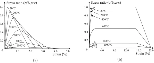
stress-strain relationship for steel is considered as specified by the Eurocode 3 (2005), Figure 1b.
(a) (b)
Figure 1 Stress-strain relationships of concrete in compression and steel at elevated temperature: (a) concrete in compression; (b) steel
Concrete heating to a maximum temperature and subsequently cooling down does not recover its initial compressive strength. The stress-strain relationships adapted to natural fires with a decreasing heating branch presented in the informative annex C of the Eurocode 4 (2005) are considered. The concrete tensile stress is considered as in Huang et al. (2003) (Figure 2), with
ε
cu=
15
ε
cr. The tensile strength reduction is considered equal to the cubic power of thecom-pressive strength reduction.
Figure 2 Stress-strain relationships of concrete in tension (Huang, et al., 2003)
0 1.0 2.0 3.0 4.0 5.0
0.2 0.4 0.6 0.8 1.0
Strain (%) Stress ratio (σ/fc,20°C)
20°C 200°C
400°C
600°C
800°C
1000°C
0 4.0 8.0 12.0 16.0 20.0
0.2 0.4 0.6 0.8 1.0
Strain (%) Stress ratio (σ/fy,20°C)
20°C
200°C
400°C
600°C
800°C 1000°C
0 ft
Tension Strain Tension stress
0.33ft
ε
cr 0.22ε
cuε
cuconcrete cracking
Latin American Journal of Solids and Structures 11(2014) 001 – 018
2.2 Finite element formulation
The finite element employed in the present work must be able to undergo large displacements and rotations, but small strains. Basic assumptions include: plane sections remain plane; there is perfect bond at the interface between materials; each element is subjected to a uniaxial state of stress; local buckling and cross section warping are not taken into account.
The corotational (CR) formulation is employed for the treatment of large displacements and rotations. Roughly speaking, the CR formulation consists of a set of axes which continuously moves and rotates with the element. Relative to this moving frame a “local” element formula-tion is defined, and large displacement effects are taken into account in the transformaformula-tion between the local and global coordinate systems. In two-dimensional problems the transfor-mations between the systems are exact, but in three-dimensional problems different formula-tions may be derived based on different definiformula-tions of the local system and assumpformula-tions relative to the global and local rotations. The present work follows the procedure developed by Crisfield (1997). A good explanation and detailed derivation is also presented by Souza (2000). The main geometric operations are briefly described below.
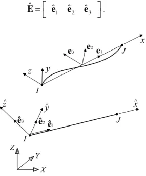
Figure 3 displays the straight undeformed element and its initial local system
x
ˆ
y
ˆ
z
ˆ
, corre-spondent to a triad of three base vectors (axes)e
ˆ
1,
e
ˆ
2 ande
ˆ
3, defined for the two nodes and which may be collected as a rotation matrixˆ
E
=
e
ˆ
1
e
ˆ
2e
ˆ
3⎡
⎣
⎤
⎦
. (3)Figure 3 Initial element spatial configuration
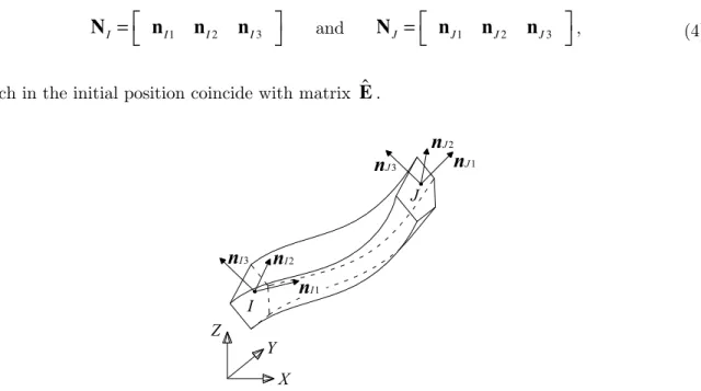
During deformation the two element nodal triads of axes will translate and rotate in space, and in the current deformed configuration, the new positions for the triads (Figure 4) are writ-ten as
X Z
Y I
ê3
ê2
ê1
y
z
x
^J I
x
^ ^
y
z
e
1e
2Latin American Journal of Solids and Structures 11(2014) 001 – 018
N
I
=
⎡
⎣
n
I1n
I2n
I3⎤
⎦
andN
J=
⎡
⎣
n
J1n
J2n
J3⎤
⎦
, (4)which in the initial position coincide with matrix
E
ˆ
.Figure 4 Nodal triads of axes in deformed configuration
The position of the triads of axes is updated by means of incremental translation and rota-tion values. The rotarota-tion increments, which cannot be simply added due to the non-commutative property of rotations in space, allow one to update the rotational variables. The rotation variables for each node may be a pseudovector, its associated rotation matrix, or a unit quaternion (Crisfield, 1997).
After element deformation, the element-attached coordinate system
xyz
, used to evaluate the “local” element displacements and strains, may be defined as follows: the x axis, which cor-responds to unit vectore
1, is defined by the direction of the line connecting the end nodes in
the deformed configuration, and the other two directions are defined by unit vectors
e
2 and
e
3(Figure 3), given by
e
2
=
r
2−
r
2
T
e
1
2
r
1+
e
1(
)
ande
3=
r
3−
r
3 Te
1
2
r
1+
e
1(
)
, (5)where the vectors
r
1,r
2 andr
3 compose the triadR
=
⎡
⎣
r
1r
2r3
⎤
⎦
. (6)The definition of this local system is not unique and the solution presented above was origi-nally suggested by Crisfield (1997). The triad
R
corresponds to an averaged rotation betweenX Z
Y I
J
n
I3n
I2n
I1n
J3Latin American Journal of Solids and Structures 11(2014) 001 – 018
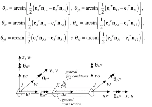
the two nodal rotations. “Local” element rotations (element degrees of freedom) maybe then recognized (Figure 5) as
θ
xI=
arcsin
1
2
e
3T
n
I2
−
e
2T
n
I3(
)
⎡
⎣⎢
⎤
⎦⎥
,θ
yI=
arcsin
1
2
e
1 T
n
I3
−
e
3 Tn
I1(
)
⎡
⎣⎢
⎤
⎦⎥
,θ
zI
=
arcsin
1
2
e
2Tn
I1
−
e
1 Tn
I2(
)
⎡
⎣⎢
⎤
⎦⎥
,θ
xJ=
arcsin
1
2
e
3Tn
J2
−
e
2T
n
J3(
)
⎡
⎣⎢
⎤
⎦⎥
,θ
yJ=
arcsin
1
2
e
1Tn
J3
−
e
3T
n
J1(
)
⎡
⎣⎢
⎤
⎦⎥
eθ
zJ=
arcsin
1
2
e
2Tn
J1
−
e
1T
n
J2(
)
⎡
⎣⎢
⎤
⎦⎥
. (7)Figure 5 Local system (CR formulation d.o.f´s are indicated by the symbol “*”)
It is assumed that the local element has seven degrees of freedom, six rotations evaluated from Equations 7 and the axial displacement
u
J in the direction
e
1 (Figures 3 and 5). The incremental relation between displacements in the global (δ
u
) and local (δ
u
ˆ
) systems is givenby
δ
u
=
∂
u
∂
u
ˆ
δ
u
ˆ
=
T
δ
u
ˆ
. (8)Matrix T is obtained by geometrical considerations, involving considerable algebraic manip-ulation, which may be found in Crisfield (1997) or Souza (2000). Its transpose gives the rela-tionship between forces in the two systems
ˆ
P
=
T
TP
. (9)The local stiffness matrix relates displacement and force increments
δ
P
=
Kδ
u
. (10)x
,
u
z
,
w
y
,
v
w
Iθ
zI*v
Iθ
yI*u
J*v
Jθ
yJ*w
Jθ
zJ*u
Iu
KI K J
Latin American Journal of Solids and Structures 11(2014) 001 – 018
Through linearization of Expression (9) with Expressions (8) and (10) one may obtain the expression for the tangent stiffness in the global coordinate system
δ
P
ˆ
=
T
TK T
+
K
g(
)
δ
u
ˆ
=
K
ˆ
δ
u
ˆ
, (11)where the geometric stiffness
K
g is given byK
g=
∂
T
T∂
u
ˆ
:
P
, (12)and where “:” represents a contraction, such that
δ
T
TP
=
δ
t
r r=13
∑
P
r=
K
g
δ
u
ˆ
, (13)and
t
r are the lines of transformation matrix
T
. To obtain the geometric stiffness matrix thevariation of
T
is required, which once again leads to a large amount of algebraic manipulation. The geometric stiffness matrix is non-symmetric. It has been observed, however, that artifi-cial symmetrization does not lead to severe convergence problems. Upon reaching equilibrium, however, symmetry is recovered.In the Newton-Raphson (N-R) scheme for fire analysis, load increments are applied prior to time increments of fire exposure. After applying a typical time increment, a heat transfer anal-ysis is performed on each integration point. With the new thermal strains and material proper-ties, the internal force is no longer in equilibrium with the applied loads, and an iterative N-R scheme is carried out to recover equilibrium. Structural collapse is identified when the numeri-cal scheme is not able to reach an equilibrium point.
2.3 Local element formulation
In the expression of the CR element stiffness formulation matrix the only requirement on the “local” element formulation is to have the same seven degrees of freedom shown in Figure 5 (indicated with the symbol “*”). The 11 degree of freedom finite element employed by Sousa Jr. and Caldas (2005) for the numerical analysis of composite columns will be used, with uncou-pled torsional stiffness added. The element is based on a total lagrangian formulation, suitable for large displacements and moderate rotations. Cubic hermitian functions are used for local transverse displacement interpolations,
v
=
Nv
Tqv
andw
=
N
w T
q
w. For the axial displacements,quadratic functions are employed, with a hierarchical axial displacement degree of freedom (d.o.f.),
u
=
N
u T
Latin American Journal of Solids and Structures 11(2014) 001 – 018
incremental level. This element performed very well for nonlinear mechanical analysis of com-posite beam-columns (Sousa Jr. and Caldas, 2005).
The Principle of Virtual Work, associated with the strain-displacement relation
"
zw
"
yv
]
)
'
w
(
)
'
v
[(
/
'
u
x
=
+
+
−
−
ε
1
2
2 2, (14)
where the prime indicates differentiation with respect to x, allows one to obtain the internal force vector
p
m=
N
xN
´
uN
xv
´
N
´
v+
M
zN
´´
vN
xw
´
N
´
w−
M
yN
´´
w⎡
⎣
⎢
⎢
⎢
⎤
⎦
⎥
⎥
⎥
d
x
m∫
, (15)and the local element tangent stiffness
k
m=
ϕ
´
u∂
N
x∂
q
⎧
⎨
⎩
⎫
⎬
⎭
TN
´
vv
´
∂
N
x∂
q
⎧
⎨
⎩
⎫
⎬
⎭
T+
N
x⎢
⎣
0
uN
´
v0
w⎥
⎦
⎛
⎝
⎜
⎞
⎠
⎟
+
N
´´
v∂
M
z∂
q
⎧
⎨
⎩
⎫
⎬
⎭
TN
´
ww
´
∂
N
x∂
q
⎧
⎨
⎩
⎫
⎬
⎭
T+
N
x⎢
⎣
0
u0
vN
´
w⎥
⎦
⎛
⎝
⎜
⎞
⎠
⎟ −
N
´´
w∂
M
y∂
q
⎧
⎨
⎩
⎫
⎬
⎭
T⎡
⎣
⎢
⎢
⎢
⎢
⎢
⎢
⎢
⎢
⎢
⎤
⎦
⎥
⎥
⎥
⎥
⎥
⎥
⎥
⎥
⎥
d
x
∫
m, (16)
where the section resultant forces
N
x,M
y,
M
z as well as their derivatives with respect to the nodal displacementsq
are obtained by employing finite element mesh at cross section level.The influence of torsion and its corresponding degree of freedom are taken into account by the inclusion of a linear relation
θ
=
T
o
/
GJ
, where the user-defined termGJ
may take intoaccount the effect of elevated temperature and/or cracking.
Warping may be included in the “local” element formulation (Franssen, 2005; Najjar, et al., 1996; Bailey, 1995), and in this case the geometric stiffness would be unchanged (Battini, et al., 2002). Nonetheless, in most cases the influence of warping in the global structural behavior of frames may be neglected.
Latin American Journal of Solids and Structures 11(2014) 001 – 018
2.4 Program implementation
The steps taken to extend the previously developed scheme by Sousa Jr. and Caldas (2005) can be summarized as follows:
- For consideration of fire action, the main modifications occur at the cross section level and include thermal analysis, considerations of degradation of materials properties in the stress-strain relationships and thermal stress-strains. Alternatively, one may perform thermal analysis in an independent program or previous step and use the temperature distribution as data for the structural analysis;
- The CR formulation allows one to analyze structures with large displacements and rotations. This implementation step is not necessary in a static analysis procedure with these capacities; - At global level, the Newton-Raphson scheme is adapted to apply time increments of fire ex-posure after load increments.
As the beam-column element is implemented in a general purpose finite element program, with object-oriented techniques employing the C++ language, the changes to the previous scheme (Sousa Jr. and Caldas, 2005) include: the implementation of a method (class) for con-sideration of adaptations at cross section level (for instance, thermal analysis); modifications to the method of calculation of the stiffness matrix and internal forces vector in order to take the CR formulation into account; and, another method for the Newton-Raphson scheme with time increments of fire exposure.
3 EXAMPLES
The beam-column finite element developed in the present work was tested against various experi-mental and numerical results. The numerical values for comparison come from results obtained from other works which used the VULCAN and SAFIR programs. Some results for VULCAN were generated with a version of the program available at Federal University of Minas Gerais (version 10.0). In all of the examples, the present formulation employed temperature-dependent material properties from Eurocode 2 (2004) or Eurocode 3 (2005).
3.1 Steel column
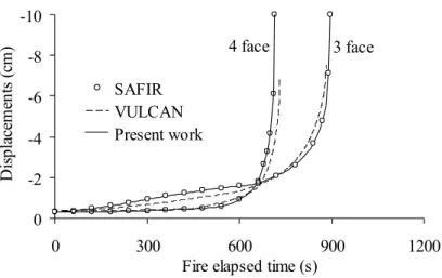
A pin-ended IPE360 steel column, 4m in length, subjected to the standard ISO 834-1 time-temperature curve with fire exposure on three and four faces was analyzed by Landesmann et al. (2005), employing SAFIR, as well as by the authors of this work, with VULCAN version 10.0 and with the present formulation. At ambient temperature the column is loaded by an axial force equal to 30% of the full plastic strength of the section, and by a constant moment (about the stronger axis and causing single curvature) which is 20% of the section’s full plastic moment.
Latin American Journal of Solids and Structures 11(2014) 001 – 018 In the analysis with VULCAN, the cross section temperatures used as input were taken as being equal to a reference temperature obtained at the centroid of the unprotected flange. For the col-umns exposed on three faces, the temperatures at the web and the protected flange were taken as 100% and 80% of this reference respectively. This distribution was based on thermal analysis of the cross section. It was found, however, that this choice of distribution does not have significant influ-ence on the results obtained.
Figure 6 Results for steel columns
3.2 Steel beam
Landesmann et al. (2005) also employed SAFIR to analyze the fire behavior of a simply supported beam, 5m in length, subjected to end moments which vary from 0.1 to 0.9 times the ambient tem-perature full plastic moment of the IPE360 cross section. For the present formulation four equal elements with four integration points were employed. The top flange’s upper face was considered protected by a material with adiabatic thermal properties.
In the analysis with VULCAN 10.0 the temperature of the protected flange was taken as being 80% of the unprotected flange for the beams with an applied moment between 0.7 and 0.9 times the plastic moment, and as being 90% in the other cases. These values were based on thermal analyses of the IPE360 profile.
-10
-8
-6
-4
-2
0
0 300 600 900 1200
Fire elapsed time (s)
Di
sp
la
ce
m
en
ts
(
cm
) 4 face 3 face
Latin American Journal of Solids and Structures 11(2014) 001 – 018
Figure 7 Results for steel beams under constant moment
Figure 7 displays the results for the mid-span displacements. The beam is initially loaded at am-bient temperature and then the time is increased to simulate fire exposure. The results were once more very similar to the ones obtained with SAFIR, while most of them were close to VULCAN as well. Version 10.0 of VULCAN does not perform thermal analysis. The relationship between tem-peratures of different parts of the section changes throughout the period of fire exposure. However, these relationships are taken as being constant in the program, and this could be the main cause of the disparities found in the results.
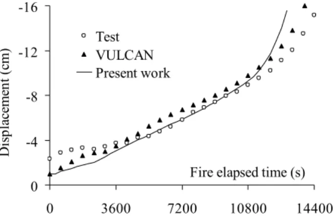
3.3 Reinforced concrete beam
Figure 8 Reinforced concrete beam
Six reinforced concrete beam specimens (one of them schematically shown in Figure 8) were tested by Ellingwood and Lin (1991) and a numerical analysis with VULCAN was carried out for three of them by Cai et al. (2003). The beams analyzed with the present formulation correspond to Beam 3 and Beam 6 from the original work and were exposed to fire on the lateral and lower faces of the cross section, while the cantilever was kept at ambient temperature. Beam 3 was subjected to standard ASTM E119 fire and Beam 6 was exposed to a SDHI (short duration high intensity) fire.
-35
-25
-15
-5
0
300
600
900
1200
1500
1800
2100
2400
Fire elapsed time (s)
D
is
p
la
ce
m
en
ts
(c
m
)
0.1 Mp
0.2 Mp
0.3 0.4 0.5 0.8
0.7 0.6
0.9 Mp
SAFIR VULCAN Present work
838
3251 1549
6100
360 102
300 1830
510 1016 1016 1016 1016 1016 510 1524
P = 44.48 kN
P P P P P Po
a
a
4 Ø 25.4
4 Ø 22.2
68 65
65 68 68 68
228
Section a-a
Latin American Journal of Solids and Structures 11(2014) 001 – 018 The concrete strength was 29.65 MPa and 34.54 MPa for Beams 3 and 6 respectively, and the rein-forcement had 495 MPa yield strength and 187244 MPa elastic modulus at ambient temperature. In the absence of complete information on concrete moisture, its effects were considered in the present work by taking a moisture value of 3% of the concrete weight. The concrete thermal conductivity was taken as the lower limit prescribed by the Eurocode 2 (2004). The load
P
o was taken here as constant and equal to 157.8kN e 111.2kN for Beams 3 and 6, respectively. Cai et al. (2003) em-ployed 20 elements in the numerical analysis, and obtained the cross section temperature distribu-tion with the three-dimensional heat and mass transfer analysis program FPRCBC-T (Huang, et al., 1996). In the present work, 16 elements were used. Figures 9 and 10 show the comparison be-tween the maximum displacements obtained with the test and by numerical analyses. The results are quite reasonable in spite of the uncertainty of some of the parameters involved and the differ-ences in the numerical modeling.
Figure 9 Maximum displacements of the span under fire (Beam 3)
Figure 10 Maximum displacements of the span under fire (Beam 6) -16
-12
-8
-4
0
0 3600 7200 10800 14400 Fire elapsed time (s)
D
is
p
la
ce
m
en
t
(c
m
) TestVULCAN
Present work
-8
-6
-4
-2
0
0 3600 7200 10800 14400
Fire elapsed time (s)
D
is
p
la
ce
m
en
t
(c
m
)
Latin American Journal of Solids and Structures 11(2014) 001 – 018
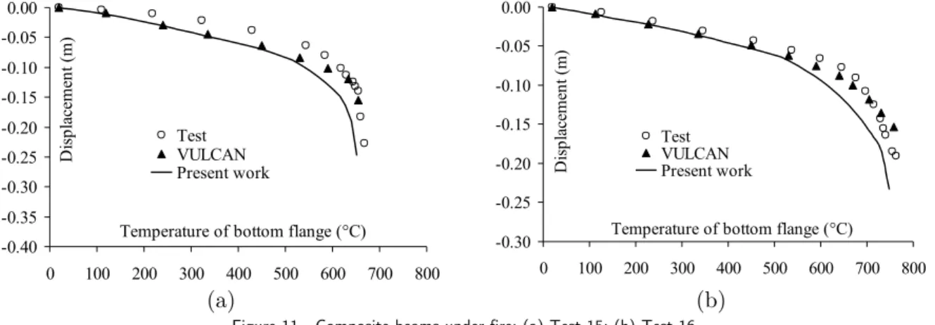
3.4 Composite steel and concrete beam
Two composite steel-concrete beams under fire conditions were tested by Wainman and Kirby (1988), and a numerical analysis with VULCAN was carried out by Huang et al. (1999). The beam cross section was composed of a steel section 254x146mm x 43kg/m connected to a reinforced con-crete slab 624x130mm with four 8mm bars of longitudinal reinforcement. The steel profile and the reinforcement bars had 255MPa and 600MPa yield strength respectively, and the concrete compres-sive strength was 30 MPa. The length of both beams was 4530mm and identical concentrated loads were applied at four points on each beam. These loads were 32.47kN and 62.36kN, respectively, for Test 15 and Test 16 [50]. The beams were exposed to standard fire (ISO 834) on their lower face. In the present analysis, material properties were taken from the Eurocode 4 with 8 finite elements with four integration points each. The displacement results (Figure 11) show good agreement between the predictions of the present work and the experimental and numerical values.
(a) (b)
Figure 11 Composite beams under fire: (a) Test 15; (b) Test 16.
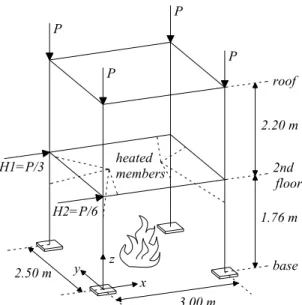
3.5 3D Steel Frame
Souza Jr. and Creus (2007) present the numerical results of the 3D steel frame depicted in Figure 12, employing SAFIR. All the cross sections are H150x150x7x10mm and the load P=250kN. The inferior beams and columns of the structure are subjected to temperature increases. The results for the displacements obtained with the present formulation and their comparison with SAFIR in the directions of loads H1 and H2 are shown in Figure 13.
-0.40 -0.35 -0.30 -0.25 -0.20 -0.15 -0.10 -0.05 0.00
0 100 200 300 400 500 600 700 800 Temperature of bottom flange (°C)
D
isp
la
ce
m
en
t
(m
)
Test VULCAN Present work
-0.30 -0.25 -0.20 -0.15 -0.10 -0.05 0.00
0 100 200 300 400 500 600 700 800 Temperature of bottom flange (°C)
D
isp
la
ce
m
en
t
(m
)
Latin American Journal of Solids and Structures 11(2014) 001 – 018
Figure 12 Three-dimensional steel frame
Figure 13 Displacement-temperature results of the 3D steel frame
3.6 Discussion
Close agreement between the results obtained in this work and the results of the SAFIR program can be linked with basic assumptions about beam elements considered in both programs. Neither the beam elements presented in this work nor those of the SAFIR program consider shear defor-mation, but both use corotational formulations. In this work, thermal analysis is performed with the boundary conditions set for the section. For each increment of exposure time to fire, thermomechan-ical analysis is performed. The SAFIR program performs thermal analysis, stored the temperatures and subsequently performs mechanical analysis (Franssen, 2005).
roof
z y
x
2nd floor
base heated
members
2.20 m
1.76 m
3.00 m 2.50 m
H2=P/6 H1=P/3
P P
P
P
0
0.01
0.02
0.03
0.04
0.05
0.06
0
200
400
600
Temperature (°C)
D
is
p
la
ce
m
en
ts
(m
)
H1
H2
Latin American Journal of Solids and Structures 11(2014) 001 – 018
The VULCAN version 10.0 considers shear deformation and uses a total lagrangian formulation, but the temperatures of parts of the section, in general, are input data, taken as a given percentage of a time-temperature curve defined by the user. Since the increases in temperature between parts of a section are generally not constant during exposure to fire, it is believed that this is the main cause of the small differences between the results obtained in examples 1 and 2.
4 CONCLUSIONS
This paper presented the implementation of a finite element for the thermomechanical analysis of 3D framed structures made of bare steel, reinforced concrete or composite steel and concrete, and their application to the analysis of structural behavior in fire conditions. The information presented here can be used and adapted to other models focused on analysis at room temperature. The pro-posed formulation displayed very good agreement when compared to well-established programs such as VULCAN and SAFIR. Generic cross sections can be considered, providing a valuable tool for the general analysis of framed structures subjected to elevated temperatures.
Future research will focus on the development of models to simulate the behavior of reinforced concrete slabs, and will combine these elements with the beam-column analysis presented here, in order to have a framework for the general analysis of buildings under fire conditions.
Acknowledgments The writers wish to thank Vallourec-Mannesmann (V&M Tubes do Brasil), CNPq (Conselho Nacional de Desenvolvimento Científico e Tecnológico) and FAPEMIG (Fundação de Amparo à Pesquisa do Estado de Minas Gerais) for their financial support.
References
Abu, A.K. and Burgess, I.W. (2010), "The effect of edge support on tensile membrane action of composite slabs in fire", Proc. SDSS’Rio 2010, 21-32.
Bailey, C.G. (1995), "Simulation of the structural behavior of steel-framed buildings in fire. Ph.D thesis, Univer-sity of Sheffield.
Bailey, C.G., Moore, D.B. and Lennon, T. (1999), "The structural behavior of steel columns during a com-partment fire in a multi-storey braced steel-frame. J. Constr. Steel Res., 52, 137-157.
Bathe, K.J. 1996. Finite Element Procedures, Prentice-Hall.
Battini, J.M. and Pacoste, C. (2002) "Co-rotational beam elements with warping effects in instability problems", Comput. Meth. Appl. Mech. Eng., 191, 1755-1789.
Becker, J., Bizri, H. and Bresler, B. (1974), "Fires-R.C. A computer program for the fire response of structures-reinforced concrete", Report UCB FRG 74-3, University of California.
Becker, J., Bizri, H. and Bresler, B. (1974), "Fires-T. A computer program for the fire response of structures-thermal", Report UCB FRG 74-1, University of California.
Block, F., Burgess, I.W., Davison, B., Plank, R.J. (2006), "The development of a component-based connection element for endplate connection in fire", Proc. Int. Workshop Struct. in Fire.
Burgess, I.W. and Plank, R.J. (1998), "Modelling the fire tests on the cardington full-scale frame", Proc. 3rd Cardington Conference.
Latin American Journal of Solids and Structures 11(2014) 001 – 018
Caldas, R. B. (2008), "Análise numérica de estruturas de aço, concreto e mistas em situação de incêndio", Ph.D thesis. Universidade Federal de Minas Gerais.
Cook, R.D., Malkus, D.S., Plesha, M.E., Witt, R.J. (2002), Concepts and Applications of Finite Element Analys-is, John Wiley & Sons.
Crisfield, M.A. (1997), Nonlinear Finite Element Analysis of Solids and Structures - Volume 2: Advanced Topics, John Wiley & Sons.
Ellingwood, B. and Lin, T.D. (1991), "Flexure and shear behavior of concrete beams during fires", J. Struct. Eng., 1176(2), 440-458.
Eurocode 2, European Standard (2004), Design of concrete structures, Part 1.2: General rules, Structural fire de-sign, EN 1992-1-2.
Eurocode 3, European Standard (2005), Design of steel structures, Part 1.2: General rules, Structural fire design, EN 1993-1-2.
Eurocode 4, European Standard (2005), Design of composite steel and concrete structures, Part 1.2: General ru-les, structural fire design, EN 1994-1-2.
Franssen, J.M. (1987), "A study of the behavior of composite steel-concrete structures in fire", Ph.D thesis, Uni-versity of Liege.
Franssen, J.M. (1997), "Contributions à la modélisation des incendies dans les bâtiments et de leurs effets sur les structures", Thèse d’agrégation, University of Liege.
Franssen, J.M. (2005), "SAFIR: A thermal/structural program for modeling structures under fire", Eng. J. AISC, 3rd quarter, 143-158.
Franssen, J.M., Pintea, D. and Dotreppe, J.C. (2006), "Numerical analysis of the effect of localised fires on com-posite steel concrete buildings", Proc. Int. Workshop Struct. in Fire.
Gillie, M., Usmani, A. and Rotter, M. (2001), "A structural analysis of the first Cardington Test", J. Constr. Steel Res., 58, 581-601.
Huang, Z., Burgess, I.W. and Plank, R.J. (2003), "A non-linear beam-column element for 3d modelling of general cross-sections in fire", Report DCSE/03/F/1, University of Sheffield.
Huang, Z., Burgess, I.W. and Plank, R.J. (2006), "Behavior of reinforced concrete structures in fire", Proc. Int. Workshop Struct. in Fire.
Huang, Z., Burgess, I.W. and Plank, R.J. (1999), "Nonlinear analysis of reinforced concrete slabs subjected to fire", ACI Struct. J., 96(1), 127-135.
Huang, Z., Burgess, I.W. and Plank, R.J. (1999), "The influence of shear connectors on the behavior of composite steel-framed buildings in fire", J. Constr. Steel Res., 51, 219-237.
Huang, Z., Burgess, I.W. and Plank, R.J. (2009), "Three-dimensional analysis of reinforced concrete beam-column structures in fire", J. Struct. Eng., 135 (10), 1201-1212.
Huang, Z., Platten, A. and Roberts, J. (1996), "Non-linear finite element model to predict temperature histories within reinforced concrete in fires", Build. Environ., 31(2), 109-118.
Iu, C.K., Chan, S.L. and Zha, X.X. (2005), "Nonlinear pre-fire and post-fire analysis of steel frames", Eng. Struct., 27, 1689-1702.
Landesmann, A., Batista, E.M. and Alves, J.L.D. (2005), "Implementation of advanced analysis method for steel-framed structures under fire conditions", Fire Safety J., 40, 339-366.
Li, G.Q. and Guo, S.X. (2006), "Analysis of restrained heated steel beams during cooling phase", Proc. Int. Workshop Struct. in Fire.
Latin American Journal of Solids and Structures 11(2014) 001 – 018
Najjar, S.R. and Burgess, I.W. (1996), "A non-linear analysis for 3-dimensional steel frames in fire conditions", Eng. Struct., 18, 77-89.
O’Connor, M.A. and Martin, D.M. (1998), "Behavior of a multi-storey steel framed building subjected to fire at-tack", J. Constr. Steel Res., 46(1-3), 295.
Parente Jr., E., Holanda, A.S. and Silva, S.M.B.A. (2006), "Tracing nonlinear equilibrium paths of structures subjected to thermal loading", Comput. Mech., 38, 505-520.
Saab, H.A. and Nethercot, D.A. (1991), "Modelling steel frame behavior under fire conditions", Eng. Struct., 13, 371-382.
Sousa Jr., J.B.M. and Caldas, R.B. (2005), "Numerical analysis of composite steel-concrete columns of arbitrary cross section", J. Struct. Eng., 131(11), 1721-1730.
Souza Jr., V. and Creus, G.J. (2007), "Simplified elastoplastic analysis of general frames on fire", Eng. Struct., 29(4), 511-518.
Souza, R.M. (2000), "Force-based element for large displacement inelastic analysis of frames", Ph.D thesis, Uni-versity of California.