This paper is about the design and construction of a platform for dynamic tests especially with people jumping, walking, etc. Initially it was tried to ind out projects already implemented in platforms and dynamic tests and to study the loads produced by movement of people on slabs and the structural response to these loads. The limits established by different standards have been also studied for these dynamic responses, taking into account the ultimate limit state, as well as the structure in service, since the human body is very sensitive to structural vibrations. Parametric studies were performed considering various conigurations of slabs (different spans, thicknesses and conditions of support) have been done, looking for a coniguration that could have natural frequency close to the frequencies of the human loads. The slab should have dimensions compatible with the available physical space, fundamental frequency below 5 Hz and maximum immediate delection compatible with the indications of the Brazilian standard NBR6118: 2007. Based on these criteria was chosen a rectangular structure consists of a solid reinforced concrete rectangular slab studded in two opposite edges of steel beams with shear connectors type U. The other two edges are free. The steel beams supporting the slab, in turn, are supported on eight metal proiles (two in each corner of the slab) that are supported on two to two short columns of steel proile H. Proiles U in steel are welded to four columns, forming a horizontal frame. Numerical analysis of the dynamic test platform have been performed for free and forced vibration, for obtaining the natural frequencies and corresponding vibration modes, considering the self-weight of the structure and the load that simulates people’s weight. After obtaining a structural coniguration that fulilled the stipulated requirements, the design of the slab taking into account the recommendations of the Brazilian standard NBR6118: 2007. The platform was built and has been done a preliminary experimental study to obtain the irst natural frequencies.
Keywords: dynamic tests, natural frequency, slabs, induced vibrations.
Este trabalho trata do projeto e construção de uma plataforma para a realização de ensaios dinâmicos especialmente com pessoas pulando, cami-nhando, etc. Procurou-se inicialmente localizar projetos já executados de plataformas de ensaios dinâmicos e estudar os carregamentos produzidos pelo movimento de pessoas em lajes e a resposta das estruturas a esses carregamentos. Foram estudados também os limites estabelecidos por diferentes normas para essas respostas dinâmicas, tendo em vista tanto o estado limite último como a estrutura em serviço, já que o corpo humano é bastante sensível às vibrações estruturais. Realizaram-se estudos paramétricos considerando várias conigurações de lajes (diferentes vãos, espes -suras e condições de apoio), buscando uma coniguração que possuísse frequência natural próxima das frequências dos carregamentos humanos. A laje deveria ter dimensões apropriadas ao espaço físico disponível, frequência fundamental inferior a 5 Hz e lecha máxima instantânea compatível com as indicações da norma brasileira NBR6118:2007. Com base em esses critérios foi escolhida uma laje retangular maciça de concreto armado engastada em duas bordas opostas em vigas metálicas com conectores de cisalhamento tipo U. As outras duas bordas são livres. As vigas metálicas de apoio da laje, por sua vez, apóiam-se sobre 8 peris metálicos (dois em cada canto da laje) que se apóiam dois a dois sobre colunas curtas de aço de peril H. Peris U de aço são soldados às quatro colunas, formando um quadro horizontal. Foram realizadas análises numéricas da plataforma de ensaios dinâmicos em vibração livre e forçada para obter as frequências naturais e os modos de vibração correspondentes, considerando o peso próprio da estrutura e o carregamento que simula o peso das pessoas. Obtida uma coniguração de estrutura que cumprisse com os requisitos esti -pulados, foi feito o dimensionamento da laje levando-se em conta as recomendações da norma brasileira NBR6118:2007. A plataforma foi construída e já foi feito um estudo preliminar experimental para obtenção das primeiras frequências naturais.
Palavras-chave: ensaios dinâmicos, frequência natural, lajes, vibrações induzidas.
Platform for dynamic tests: preliminary studies,
design and construction
Plataforma de ensaios dinâmicos: estudos preliminares,
projeto e construção
J. E. CAMPUZANO a georcam2003@yahoo.es
R. DE CASTRO b djyopa@gmail.com
S. ÁVILA c avilas@unb.br
G. DOZ d graciela@unb.br
a Universidade de Brasília, Faculdade de Tecnologia, Programa de Pós-Graduação em Estruturas e Construção Civil, georcam2003@yahoo.es, Brasília DF, Brasil.
b Universidade de Brasília, Faculdade de Tecnologia, Departamento de Engenharia Civil e Ambiental, djyopa@gmail.com, Brasília DF, Brasil. c Universidade de Brasília, Faculdade do Gama, avilas@unb.br, Brasília DF, Brasil.
d Universidade de Brasília, Faculdade de Tecnologia, Programa de Pós-Graduação em Estruturas e Construção Civil, graciela@unb.br, Brasília DF, Brasil. Received: 12 Apr 2012 • Accepted: 25 Sep 2012 • Available Online: 08 Feb 2013
Abstract
1. Introduction
The study of induced vibrations in slabs has been intensiied in recent years. There are several causes that led to this reality and, among the most important may be mentioned the increas-ing use of more resistant materials that lead to more slender and lexible slabs and the use of structures for activities that were not initially foreseen in the original project . These factors have contributed with increasing frequency to the appearance of vibration problems in structures and, mainly, in the slabs. Flex-ible structures are generally more susceptFlex-ible to the effects of dynamic loads. A major factor is the low natural frequency pre-sented by this type of structure, which responds, in an ampliied way, to dynamic loads that present a frequency close to the one in the structure. Among the dynamic loads of low performance frequency that are common in slabs, can be mentioned the loads generated by human activities, such as, walking, dancing, jumping, etc.
Therefore, may be mentioned several reports of structures that presented problems related to dynamic loads response, generated by movements of people, including the Maracanã (RJ), Nilson-Nelson (DF), Mangueirão (PA) stadiums, the Universal Church of the Kingdom of God (RJ) and the Millennium Footbridge (London, England). (Faisca, [1]).
The Millennium Footbridge, located in London, was interdicted less than an hour after its opening, due to the presentation of strong lateral vibrations. The walkways suspended of the Hyatt Regency hotel in Kansas City / USA presented excessive vibrations during a dance championship, which culminated in the collapse of the structure and caused the death of 114 people and injuried another 200. (Ramroth, [2]).
Thornton et al, [3] apud Ritchey and Kenneth, [4], studied two buildings cases, a one used as a high school, and the other as a college, both with large spans and spaces, and containing rooms for physical activities conduction, in which were perceived exces-sive vibrations, causing discomfort to users.
Webster and Vaicaitis, [5], apud Ritchey and Kenneth, [4] investi-gated the strong vibrations present in a system of mixed slabs, of a building in the city of New York, produced by people who used to dance near a restaurant, causing fear to occupants of the restau-rant during dinner. These vibrations produced accelerations in the slab of up to 7m/s² and, displacements of 3.3 mm.
Battista and Varela [6] found problems with excessive vibrations in loors of residential buildings, even though they met the criteria standards for structural design.
In cases like those mentioned structures becomes necessary a thorough study of the vibrations induced by the activities that peo-ple develop, because these oscillations can cause problems of dis-comfort and injury to health, and, in extreme cases, can endanger the safety of the structure. It is also important to mention that the characterization of this type of loads is not yet consensus among researchers in the ield and should be studied, besides other as -pects, the effect of the crowd, the lateral vibrations, etc.
Moreover, for the development of a reliable theoretical model for the analysis, design and veriication of buildings slabs under the action of dynamic loads induced by people, it is important that this model is validated through theoretical and experimental correlations of the structure dynamic responses. Hence the importance of being able
to perform experimental tests on slabs subjected to dynamic loads. Based on the foregoing, it is numerically studied the dynamic behavior of some conigurations of slabs subjected to loads induced by man, with a view to build a platform for dynamic tests. The structures are modeled using a inite element pack -age (ANSYS 2007, [7]) that allows the realization of modal and transient analyzes, providing as results images, animations, displacements records, nodal velocities and accelerations, as well as, displacement amplitude versus frequency and request-ed moments graphics, usrequest-ed for dimensioning the structure. With these elements is done the slab scaling, which will be used as test platform to simulate different situations of human loads, thereby, allowing both, numerical characterization of loads in-duced by people moving, as wel as the evaluation of the struc-tural response.
1.1 Considerations about induced load
The vibrations caused by human activities may occur either ver-tically or horizontally (lateral and longitudinal), motivated by the vertical and horizontal components of the force exerted by peo-ple (Bachman, [8]). This force can, generally, be considered as periodic (CEB, [9]) and, can be represented by a static portion representative of the person´s weight of the person and, by a Fourier series, in which, the first harmonic has a frequency vary-ing between 1, 8 and 3.5 Hz accordvary-ing to the activity performed (step frequency). In the other hand, the following harmonics are characterized by multiple frequencies of that first one. According to Bachmann and Ammann [10], a person jumping produces a vertical force which can be written as:
(1)
Where:
Kp = Fp,max/G:Dinamic impact factor. Fp,Max: Dynamic load peak.
G: Person´s weight (generally considered G=800N) tp: Contact duration.
Tp= 1/fs: Loading period.
Are used types of elements that can better simulate the behavior of each structural component molded in this case the elements SHELL63, BEAM4, and SOLID65 SOLID45 (see Figure 1). The SHELL63 element has six degrees of freedom at each of its four nodes, translation in X, Y and Z and rotation about the same, is shown to simulate the behavior of membranes and accepts ship-ments in its own plane and orthogonal to it.
In the other hand, BEAM4 already has six degrees of freedom in each of its two nodes (I, J), translation in X, Y and Z and, rotation around themselves. It is an uniaxial element capable of modeling tension, compression, torsion and bending. The el-ement SOLID65 has eight nodes, each with three degrees of freedom, which are translations according to the axes X, Y and Z. It is able to simulate the behavior of materials such as con-crete, ie, which can crack when subjected to tensile stresses and suffers crushing in compression. The armors can be in-cluded and resist only to axial forces. It is possible to consider the non-linearity of the materials. This element was used in the discretization of the concrete slab and the four pillars for the most sophisticated models.
Finally, the element SOLID45 was used to simulate the behavior of the metal proiles. Likewise the SOLID65, the SOLID45 also has eight nodes, each node having three degrees of freedom relating to translations concerning X, Y and Z. The SOLID45 also allows considering the plasticity and the orthotropic material.
As mentioned initially, modal analyzes are performed using the computer package for several structure conigurations. The analy -sis results for all proposed structures are discussed and evaluated for determining the structure to be projected. Only for the chosen structure, are also made static and dynamic analyzes.
As already mentioned, another aspect of great importance in the analysis of induced vibrations in a structure is related to the num-ber of people in action. This is due to the fact that when a group of people moves synchronously or approximately synchronized, the impact factor produced is high, which generates large values for the induced loads in the structure. The experiments conducted in 1985 by Allen (Gomes, [12]) indicate that the impact factors can be greater than 5, when the number of people increases.
A rigorous mathematical description of the force exerted by several pedestrian is quite complex. Indeed, when more than one person performs movements in a structure occurs the superposition of the effects of each one on the structure, so that, at certain moments, the vibration amplitudes will be added or subtracted, depending on the frequency or phase. Hence the importance of further study, based on experimental results, the characterization of the load in-duced by people on the move.
2. Software tool
In this paper are analyzed numerically different slabs with views to design of the dynamic tests deck, mentioned above. The discreti-zation of the different structures analyzed is performed using the software (ANSYS 2007, [7]).
Are used the type of elements that better simulate the behavior of each molded structural component, in this case, the elements SHELL63, BEAM4, and SOLID65 SOLID45 (see Figure 1). The SHELL63 element has six degrees of freedom at each of its four nodes, translation in X, Y and Z and rotation around themselves, is indicated to simulate the behavior of membranes and accepts shipments in its own plane and orthogonal to itself.
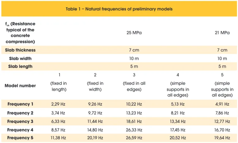
From modal analyzes (see Table 1) it was possible to realize the inluence of various factors on the natural frequencies of the struc -ture. Among them it is worth mentioning the compressive strength of the concrete and the slab thickness. It was noted that slabs with equal sides presented fundamental frequency lower than others of the same area but, with a rectangular shape.
These results enabled the development of a more complete model, with the goal of checking how the rigidity of other structural compo-nents of the structure (beams and columns) could inluence the dy -namic behavior of the platform. For this model were used SOLID65 elements for the slab and pillars and, SOLID45 for metal beams. So if the choice was for a model of dimensions 6.1 mx 4.9 m, which was characterized by a fundamental frequency of 4.48 Hz while the second reached 7.11 Hz, far enough from the irst frequency, decreasing the possibility of coupling modes.
3.2 Complete model
The slab structural scheme chosen for construction with dimen-sions and details of the support system are shown in Figure 3. It was considered an overload for sizing of 1.0 kN / m² , which results in a smaller dimension than recommended by ABNT NBR 6120:1980 [14] for residential slabs. Yet, that overload seems safe, due to the use to which the platform will be intended for, therefore, considering a person with a mass of 80 kg, the slab will be able to support 0535 people per square meter, or a total of 16 people in the slab. The requested times were obtained through performed static analysis. For a safe scaling, the positive requested time was obtained from the model which considers the simple support in
3. Numerical Analysis
3.1 Initial model
The goal of the analysis is to provide subsidies to build a platform for dynamic tests that will enable the study of loads induced by human activities. For this reason, it is important that the platform presents a natural frequency below 5 Hz while the maximum de-lection should remain at levels close to those recommended by the Brazilian standards (ABNT NBR 6118:2007, [13]).
Initially, a numerical study is conducted to determine the dimen-sions of the platform that meet the speciications of size and dy -namic characteristics mentioned. The model consists of a rectan-gular solid concrete slab, clamped on two of their edges while the other two edges of the support slab are free, as shown in Figure 2. Not considering the pillars and beams, initially.
Figure 2 – Dynamic tests platform - simplified model
Table 1 – Natural frequencies of preliminary models
f (Resistance
cktypical of the
concrete
compression)
25 MPa
21 MPa
Slab thickness
7 cm
7 cm
Slab width
10 m
10 m
Slab length
5 m
5 m
Model number
1
(fixed in
length)
2
(fixed in
width)
3
(fixed in all
edges)
4
(simple
supports in
all edges)
5
(simple
supports in
all edges)
Frequency 1
2,29 Hz
9,26 Hz
10,22 Hz
5,13 Hz
4,91 Hz
Frequency 2
3,74 Hz
9,72 Hz
13,23 Hz
8,21 Hz
7,86 Hz
Frequency 3
6,33 Hz
11,44 Hz
18,61 Hz
13,34 Hz
12,77 Hz
Frequency 4
8,57 Hz
14,80 Hz
26,33 Hz
17,45 Hz
16,70 Hz
beams and, the requested negative time was obtained through the model which considers the beams settings. Therewith, was per-formed a checking on the useful height of the slab as well as the dimensioning of the armors. The delection calculated exceeded the maximum standard recommended in approximately 10 mm, considering an acceptable value, since the slab will be used as a platform for dynamic tests.
3.2.1 Static, modal and transient analysis
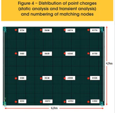
With the inal dimensions of the chosen platform, were performed static, modal and transient analysis, considering the model on Figure 3. For static analysis was considered the actuation of 16 people spaced 1.5 m, each one with a weight of 800 N. In addition to this loading, the analysis also considered the own weight of the structural elements. In Figure 4 we can see the distribution of point charges.
For modal analysis was considered the own weight obtained from the physical characteristics listed in Table 2.
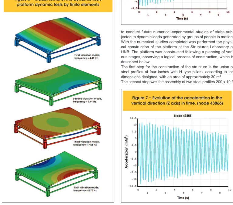
In Figure 5 are presented the irst three mode shapes corre -sponding to the irst three natural frequencies of the structure, as well as, the sixth mode shape corresponding to the sixth frame frequency. For the irst natural frequency is clearly noted that this vibration mode is associated to the effects of vertical bending
of the slab. For the second and third natural frequencies of the structure, are noted modes with lateral bending of the steel U-type proiles, that´s due to low rigidity of proiles and lack of lock -ing between themselves.
The sixth mode shape is characterized by torsion of the slab (ac-cording to the mode of the slab only) and is shown in Figure 5. For transient analysis was simulated a gym class with dy-namic loading acting for 10 seconds with 16 people jump-ing. The computation time was subdivided into time intervals of 0,05 s. Was adopted a dynamic excitation frequency of 3.4 Hz, characteristic of the considered aerobic activities (CEB,
Figure 3 – Schematic drawing and general
measures of dynamic testing platform,
mounted at the Structures Laboratory
Figure 4 – Distribution of point charges
(static analysis and transient analysis)
and numbering of matching nodes
Table 2 – Approximated own weight
of the platform of dynamic tests
Material
of each part
Own weight
Steel base
0,447 kN
Steel Pilar type H
2,112 kN
U 4 inch Steel profile
2,595 kN
Steel profile W 200 x 19,3
2,264 kN
Stiffeners
0,045 kN
Shear connectors
0,126 kN
Concrete slab
74,820 kN
Approximate total weight
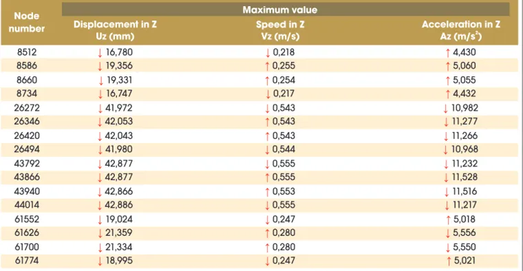
[9]). In this analysis were obtained, for each node, graphs in-dicating the displacement, velocity and vertical acceleration over 10 seconds. In Figures 6 and 7 were observed respec-tively the deformation and the maximum acceleration of node 43866. Regarding accelerations may be mentioned that they exceed the maximum values allowed in the practical guide by Murray et al [15], probably because of their low stiffness. Table 3 shows the maximum values of the dynamic response of the structure at the nodes of Figure 4. In red are indicated direc-tions of displacement, velocity and acceleration.
3.3 Stages of the construction of the platform
of dynamic tests
The platform of dynamic tests indicated in Figure 3 was designed
to conduct future numerical-experimental studies of slabs sub-jected to dynamic loads generated by groups of people in motion. With the numerical studies completed was performed the physi-cal construction of the platform at the Structures Laboratory of UNB. The platform was constructed following a planning of vari-ous stages, observing a logical process of construction, which is described below.
The irst step for the construction of the structure is the union of steel proiles of four inches with H type pillars, according to the dimensions designed, with an area of approximately 30 m². The second step was the assembly of two steel proiles 200 x 19.3
Figure 5 – Modal forms of the dynamic tests
platform dynamic tests by finite elements
Figure 6 – Evolution of displacement in the
vertical direction (Z axis) in time. (node 43866)
W type, with their respective U-type shear connectors and the steel U-type proiles of four inches, closing the top frame and thereby, providing greater rigidity to the structure.
The third step in constructing the platform was the installation of wood and metal bracing in order to withstand the shape of the concrete slab. All this temporary shoring structure was built on the same level of vertical pillars and horizontal beams levels and wood forms.
The fourth step was the installation of the armor with steel bars type ASTM A 572 Grade 50. For positive reinforcement toward the slab length (X direction) were placed 39 bars 5.0 m length and gauge of 6.5 mm spaced every 15 cm. For the armor in the perpendicular direction (Y direction), were placed 41 bars of 6,1m length and gauge of 12.5 mm spaced every 11.8 cm. Furthermore, It was performed the installment of the negative armor in the region of the lexible collet, which consisted in 25 bars in each board, resting on the steel gauge proiles of 12.5 mm and 1.82 m length.
The ifth step consisted in the concreting of the slab until it achieved a thickness of 10 cm using concrete pumped with fck of 25 MPa.
The sixth step was the process of curing the slab, which was done during 30 days. In the irst 7 days, water was putted on the slab within regular intervals of 2 hours. On the other 23 days, the cure was done every couple days, always checking that the cloths that covered remained moist. Throughout the process the cloths were covered with plastic.
At last, the steel and wood shoring was removed after 35 days of concreting. Figure 8 shows photographs of different stages of the construction of the dynamic tests platform construction.
3.4 Experimental tests
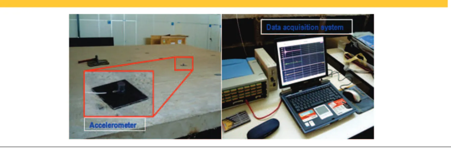
To obtain the natural frequencies of the platform of dynamic tests, it was stimulated with impacts through the use of a steel sledge-hammer and a rubber placed on the surface of the slab. The re-sponse was measured using a mobile accelerometer which was been displayed at different points of the slab (see igure 9), using metal plates. The piezoelectric accelerometer used is the 4366 type, manufactured by Brüel & Kjaer, with mass approximately equal to 10 grams and sensitivity of 4.80 pC/ms-2, connected to a system of data acquisition comprised by a module ADS2000, manufactured by Linx Tecnologia Eletrônica, containing two conditioned plates of AI-2164 type, each with 16 channels of data acquisition. Data were monitored and recorded using the software AqDados 7. The acquisi-tion system is conigured to acquire records from a channel (channel 0) corresponding to the accelerometer was placed on the platform slab at time instants of 5x10⁻³ s resulting in a sampling frequency of 200 Hz (1/Δt) . In this case, the cutoff frequency or the Nyquist frequency was 100 Hz (1/2Δt) and the test duration was 15 seconds. Data were monitored and recorded using the software AqDados 7. The acquisition system was conigured to acquire records from a channel (channel 0) corresponding to the accelerometer placed on the platform slab, at time instants of 5x10⁻³ s, resulting in a sam-pling frequency of 200 Hz (1/Δt) . In this case, the cutoff frequency or the Nyquist frequency was 100 Hz (1/2Δt) and the test duration was of 15 seconds.
It was noted that the two irst natural frequencies of the platform, obtained experimentally in the different tests were close to the fre-quencies numerically obtained with the element model type Sol-id65 and Solid45 and, as shown in Table 4.
Table 3 – Displacement, speed and acceleration in Z direction (vertical), for the analyzed nodes in transient analysis
Node
number
Maximum value
Displacement in Z
Uz (mm)
Speed in Z
Vz (m/s)
Acceleration in Z
2Az (m/s )
8512
↓
16,780
↓
0,218
↑
4,430
8586
↓
19,356
↑
0,255
↑
5,060
8660
↓
19,331
↑
0,254
↑
5,055
8734
↓
16,747
↓
0,217
↑
4,432
26272
↓
41,972
↓
0,543
↓
10,982
26346
↓
42,053
↑
0,543
↓
11,277
26420
↓
42,043
↑
0,543
↓
11,266
26494
↓
41,980
↓
0,544
↓
10,968
43792
↓
42,877
↓
0,555
↓
11,232
43866
↓
42,877
↑
0,555
↓
11,528
43940
↓
42,866
↑
0,553
↓
11,516
44014
↓
42,886
↓
0,555
↓
11,217
61552
↓
19,024
↓
0,247
↑
5,018
61626
↓
21,359
↑
0,280
↓
5,556
61700
↓
21,334
↑
0,280
↓
5,550
Figure 8 – Different steps of constructing the dynamic tests platform
4 Conclusions
It was designed and built a platform for dynamic tests consisted of a reinforced concrete slab supported by steel beams and columns, for experimental studies with people walking, dancing and jumping. Initially were studied various platforms with several geometric fea-tures, presenting fundamental frequencies below 5 Hz, in order that the structure is strongly stimulated by loads induced by human activities, which are characterized by frequencies in a range below 5 Hz. Moreover, was ensured that the second and third frequen-cies were away from the irst one, so as to avoid the phenomenon of mode coupling.
Once chosen the inal geometry, also taking into consideration the constraints of space at the Structures Laboratory of UNB, began the numerical analysis to obtain strains and stresses necessary to design the platform.
The dynamic analysis of the platform was initially characterized by a modal analysis, which provided the irst three natural vibra -tion modes of the structure and their respective frequencies. It was noted that the irst vibration mode presents a predominance of the effects of the slab vertical bending. The following two modes are characterized by lateral bending of steel U-type proiles, which connect the pillars, due to the low stiffness of the proiles and the lack of lock between them.
The numerical vibration frequencies associated with these modes present values between 4.48 and 7.61 Hz Hz. The irst value is close to the frequencies generated by the dynamic loads from peo-ple practicing physical activities. Therefore, we conclude that these modes are likely to be stimulated in tests simulating gym exercises. Following, were also performed the static and transient analyzes simulating aerobic activities with a group of 16 people. We ob-tained the static displacements of the slab and the ones caused by the simulation of a gym class, and the points of the structure with higher speed and vertical accelerations.
From the static analysis was noted that the moments of project considered by Borges, [16], are superior to the moments of static and transient analysis of this work. It is concluded, therefore, that these meet the requirements for which will be used the dynamic testing platform.
In the transient analysis were veriied large deformations, due to dynamic loading generated by simulations of people in jumping ac-tivity during a gym class. It was also observed that from the central region of the slab results the most requested, with higher speeds and accelerations, which do not meet the consulted standards. These accelerations have very high values compared to those
re-quired by the standards due to low stiffness that presents the slab and the lack of ongoing support, among other factors. It is impor-tant to make clear that the platform was designed and built with the aim of presenting excessive vibrations for experimental studies. The frequencies obtained experimentally showed results near to the frequencies numerically calculated and, it is believed that the differ-ences observed are due to the type of support considered in numeri-cal analysis, crimping, which in practice is not a perfect setting.
5. Acknowledgements
The authors acknowledge the inancial support from CAPES and Professor Yosiaki Nagato for the collaboration throughout the work.
6. References
[01] FAISCA, R.G. Caracterização de cargas dinâmicas geradas por atividades humanas, Tese de Doutorado-COPPE/UFRJ, Universidade Federal do Rio de Janeiro, UFRJ, Rio de Janeiro, Dezembro de 2003. [02] RAMROTH, WILLIAM G. JR. Planning for Disaster,
How Natural and Manmade Disasters Shape the Built Environment.
[03] THORNTON, C.H., CUOCO, D.A., VELIVASAKIS, E. E. “Taming Structural Vibrations.” Civil Engineering (New York), 60 (11), 1990. pp 57-59.
[04] RITCHEY, JHON KENNETH, Application of Magneto- Rheological Dampers in Tuned Mass Dampers for Floor Vibration Control, Master of Science, Faculty of the Virginia Polytechnic Institute and State University, Blacksburg, Virginia, October 2003. [05] WEBSTER, A. C. AND VAICAITIS, R. “Application of
Tuned Mass Dampers to Control Vibrations of Composite Floor Systems.” AISC Engineering Journal., 3rd Qtr, 1992, pp 116-124.
[06] BATTISTA, R.C., VARELA, W.D., Medidas corretivas para vibrações de painéis contínuos de lajes de edifícios, XXX Jornadas Sul-Americanas de Engenharia Estrutural, Brasil. 2002. [07] ANSYS, Swanson Analysis Systems,
Version 10.8.0.7, 2007.
[08] BACHMANN, H. Lively footbridges- a real challenge. International Conference on Design and Dynamic Behaviour of Footbridges – Footbridges 2002, Paris, França.
Table 4 – Natural frequencies of the dynamic tests platform and error percentages
regarding the experimental frequencies
Frequency
No
Experimental
Frequencies
Frequencies
Solid65 and
Solid45
Frequencies
Shell63 and
Beam4
Solid65
and
Solid45
Shell63
and
Beam4
f1
4,20 Hz
4,48 Hz
3,83 Hz
6,67%
8,81%
f2
7,23 Hz
7,11 Hz
5,84 Hz
1,66%
19,23%
[09] CEB. Vibration problems in structures. Practical Guigelines. Bulletin D´Information No 209. Commité European du Béton, Zurich, August, 1991.
[10] BACHMANN, H., AMMANN, W. Vibrations in Structures Induced by Man and Machines, 1987. [11] DALLARD, P., FITZPATRICK, A. I., FLINT, A.,
LE BOURVA, S., LOW,A., SMITH, R. M. R., WILLFORD, M. The London Millennium Footbridge. The Structural Engineer, Vol. 79/No 22.
November 2001.
[12] GOMES, D. H. M. Controle das vibrações induzidas em passarelas para pedestres. 2006. Dissertação de Mestrado, Programa de Pós-Graduação em Estruturas e Construção Civil, UnB, Brasília, Brasil.
[13] ASSOCIAÇÃO BRASILEIRA DE NORMAS TÉCNICAS. NBR 6118: Projeto e Execução de Estruturas de Concreto, Rio de Janeiro, 2007.
[14] ASSOCIAÇÃO BRASILEIRA DE NORMAS TÉCNICAS. NBR 6120: Cargas para o Calculo de Estruturas de Ediicações, Rio de Janeiro, 1980.
[15] MURRAY, T. M., ALLEN, D.E., UNGAR, E.E., Floor vibrations due to human activity, second printing,
October 2003.
[16] BORGES, R. DE C. E., Estudo preliminar com vistas à construção de uma plataforma para ensaios dinâmicos, Monograia de projeto inal 2, Universidade de Brasília, Faculdade de Tecnologia Departamento de
![Figure 1 – Types of elements used in the model (ANSYS 2007, [7])](https://thumb-eu.123doks.com/thumbv2/123dok_br/18860371.417824/3.892.66.832.676.1137/figure-types-elements-used-model-ansys.webp)