Developments and Needs for International Practice
Joint IABSE – fib Conference Dubrovnik, Croatia, May 3-5, 2010
Topic 5.4: Existing Structures: Comparisons with Codes
A STUDY ADDRESSING THE EC8-PART 3
ASSESSMENT PROCEDURES FOR EXISTING RC
STRUCTURES
Xavier Romão*, Raimundo Delgado* & Aníbal Costa**
* Civil Engineering Department, Faculdade de Engenharia da Universidade do Porto Rua Dr. Roberto Frias, 4200-465 Porto, Portugal
** Civil Engineering Department, Universidade de Aveiro Campus Universitário de Santiago, 3810-193 Aveiro, Portugal
Keywords: Max 10 keywords
Abstract: The structural safety assessment procedures proposed in Part 3 of Eurocode 8
(EC8-3) for the case of reinforced concrete structures are addressed. The practical evaluation of the member chord rotation demand according to EC8-3 is examined in detail along with several alternative formulations. The need for these formulations is demonstrated by presenting example situations where the EC8-3 proposal is difficult to apply. The effectiveness of the proposed approaches is assessed through an example application and recommendations for their practical use are defined.
1.
INTRODUCTION
The current widespread interest in methodologies addressing the assessment and the retrofit of existing constructions reflects the global perception that such constructions are exposed to inadequate levels of seismic risk. The need for rational interventions on the built environment led to the development of several normative documents and guidelines specifically addressing the seismic performance assessment of existing buildings [1-5]. In this context, the structural safety assessment procedures proposed in Part 3 of Eurocode 8 (EC8-3) [4] for the case of reinforced concrete (RC) structures are addressed herein. The practical evaluation of the member chord rotation demand according to EC8-3 is examined in detail along with several alternative formulations. The need for these formulations is demonstrated by presenting example situations where the EC8-3 proposal is difficult to apply. The effectiveness of the proposed approaches is assessed by comparing their performance with that of the EC8-3 procedure in situations where the application of the latter is straightforward. The comparisons are performed for a RC example structure, considering static and dynamic nonlinear analysis methods, and for earthquake intensity levels associated to the three EC8-3 Limit States (LSs) - the Near-Collapse (NC), the Significant Damage (SD) and the Damage Limitation (DL) LSs. Recommendations for the chord rotation demand evaluation are defined based on the application results.
2. REVIEW OF THE CHORD ROTATION DEMAND
The quantification of the chord rotation θ at a given section A of a structural member, θA,
involves the consideration of a second cross section B within the member. According to [7],
θA is the angle between the chord connecting the centroid of the two sections and the
tangent to the member axis at section A. In analytical terms, θA can be written as:
( )(
)
B A x A xx x
Bx x
Bx dx
Aθ
=
∫
φ
−
−
(1)where xA and xB are the abscissas of the two sections and
φ
( )
x represents the curvatureevolution between sections A and B. EC8-3 proposes a similar definition, specifying section B as that corresponding to the point of contraflexure. In this case, the chord rotations θ1 and θ2 of the two member ends, which are the sections of interest, are:
( )(
)
1 0 Ls x Ls Lsx x
x x dx
θ
=
∫
φ
−
; 2( )(
)
Ls L Ls Ls xx x
x L x
dx
θ
=
∫
φ
−
−
(2)where xLs is the abscissa of the point of contraflexure. Alternatively, θ1 and θ2 can also be
defined, in a more geometrically related fashion, by the following approaches (Fig. 1)
1 1a 1b
θ θ
=
−
θ
;θ
2=
θ
2a−
θ
2b (3)where θ1a and θ2a represent the contribution of the deflection at xLs with respect to the initial
member configuration and θ1b and θ2b correspond to the nodal rotation, considering
clockwise rotations to be positive. Although Eqs. (2) and (3) are equivalent, there are situations where their application is not straightforward. In this context, attention is first drawn to the EC8-3 definition of the point of contraflexure based on the moment-shear ratio
M/V at the end section, usually identified as the shear-span Ls. It is known that xLs and Ls
will only coincide under certain conditions, namely if the member under analysis is not subjected to any transversal loading, i.e. for the case of a typical frame column. In beams, which are usually subjected to gravity loading, the approximation of xLs by Ls may produce
acceptable results under some conditions, e.g. when the influence of the gravity loads is small when compared to that of the earthquake loading. In situations where the gravity loading is significant, two points of contraflexure, with abscissas xLs1 and xLs2, may occur
within the member length. In such cases, the value of xLs associated to Eqs. (2) and (3) must
be replaced by that of xLs1, for the case of θ1, and by that of xLs2, for the case of θ2.
xLs θ1a θ θ1b θ2 θ2b θ2a x* δ1 1
Figure 1: Chord rotation definition.
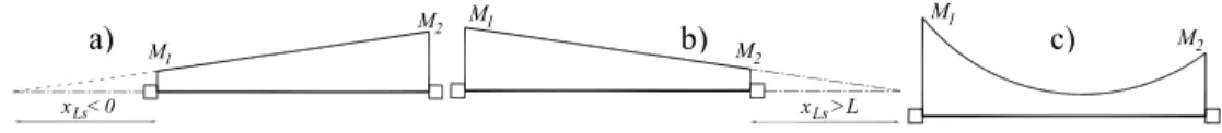
Further difficulties may arise in cases where there is no point of contraflexure within the member span. For example, by considering the moment diagrams represented in Figs. 2a) and b), typically found in columns, the value of xLs (the abscissa that would correspond to a
moment equal to zero) can be negative or larger than the member length. The case represented in Fig. 2c) is another possibility which may occur in short beams. In this case,
xLs is undefined. Under such conditions, the quantification of the chord rotation following
the EC8-3 procedure may lead to inadequate results.
x <Ls 0 M1 M2 M2 M1 x Ls>L M2 M1
Figure 2: Moment diagrams causing difficulties in the chord rotation evaluation.
3. PROPOSALS FOR CHORD ROTATION DEMAND
3.1 Alternative interpretations for xLs
When the point of contraflexure is undefined, the proposed alternative for xLs is that
corresponding to the distance between the end section under consideration and the section of minimum moment (in terms of absolute value). For columns this means that, for the situations of Figs. 2a) and b), the member safety assessment in terms of deformation is only relevant at the section with the higher absolute moment. This reflects the assumption that geometry and reinforcement are constant along the member. The application of Eqs. (3) requires that only the expression of the relevant end section is evaluated. For beams, Fig. 2c), since both end sections are significant, the proposed alternative defines xLs as the
abscissa corresponding to that of the section closer to having a zero moment.
3.2 Evaluation of the chord rotation without quantifying xLs
Three alternative approximate methods are proposed for the evaluation of the chord rotation without requiring the quantification of xLs. The first method is adapted from the
displacement-deformation relationship under large displacements proposed in [8] for frame elements where one of the chord rotation terms can be obtained without evaluating xLs by:
1a 2a
d L
yθ
=
θ
=
(4)where dy is the relative transversal displacement of sections 1 and 2. The second alternative
method is suited for structures modelled by frame elements with plastic hinges where the nonlinear behaviour is defined by moment-curvature relations. In this approach, curvature demand is assumed to be uniform along the plastic hinge length Lpl and is obtained, for
example, by the midpoint integration rule. Assuming that the most important contribution to the chord rotation comes from the plastic hinge deformation, θ1 and θ2 are:
1 1
L
pl,1θ φ
= ⋅
;θ
2= ⋅
φ
2L
pl,2 (5)where φ1 and φ2 represent the constant curvature of the two member ends, and Lpl,1 and Lpl,2
are their corresponding plastic hinge lengths. The third method is a variant of method 1 (application of Eqs. (3) considering Eq. (4)) combined with the assumptions proposed in [6]. For the case of columns under seismic loading, this study states θ1a and θ2a are more
significant than θ1b and θ2b, respectively. Hence the study suggests that the chord rotation
demand of column end sections could be obtained by θ1a and θ2a only. Furthermore, since,
according to method 1, the quantification of these components is approximated by Eq. (4), the third method proposed considers Eq. (4) for the evaluation of the chord rotation demand in columns. For beams, the third approach follows the suggestion of [6] where the contribution of θ1a and θ2a is neglected and the chord rotation of beam end sections is
approximated by the components θ1b and θ2b.
4.
EXAMPLE APPLICATION: THE ICONS FRAME
The ICONS frame is a four-storey, three-bay RC bare frame designed and built at the Joint Research Center in Ispra, Italy, for pseudo-dynamic testing [9]. Characteristics and cross section reinforcement details of the frame are found in [9].
The nonlinear response analysis of the frame under earthquake loading was carried out using a two-dimensional analysis platform for the study of the nonlinear response of multi-storey RC buildings [10]. Elements are modelled with plastic hinges located at the member ends, where inelastic flexural behaviour is considered. Control sections are located at the member ends following the numbering presented in Fig. 3 (numbers in italic refer to end sections of beams). A C16/20 concrete and a S235 steel were selected with mean values of the relevant material properties. The inelastic behaviour of the plastic hinges is defined by moment-curvature relations [11]. Hysteretic behaviour of the members was modelled by the piecewise linear Costa-Costa model [7], considering stiffness degradation and pinching effects. The values of Lpl, were considered equal to the depth of the member
cross section for beams and equal to half of the depth of the member cross section for columns. Damping was of the Rayleigh type and was only considered for the LS of DL.
Figure 3: Elevation view of the ICONS frame.
Seismic demand was set for Zone 1 of the Italian territory considering a soil of type B. According to [12], the considered PGAs for the different LSs are 0.14g, 0.35g and 0.525g for the LSs of DL, SD and NC, respectively. Pushover analysis of the frames was performed using the uniform and the modal force patterns referred by EC8-3. When nonlinear dynamic analysis was considered, two different sets of accelerograms were used to evaluate the structural demand. The first set is made of seven artificial spectrum-compatible accelerograms with 15 seconds for each LS. The second set has also seven records and is one of the unscaled real ground motion sets proposed in [13].
5. STRUCTURAL ANALYSIS RESULTS
5.1 Initial considerations
For the purpose of the presentation of the results, the considered chord rotation quantification methods (CRQMs) are, hereon, termed according to the following:
• CRQM 1 – the chord rotation obtained using Eqs. (3), considering the alternatives proposed in Section 3.1 when necessary;
• CRQM 2 – the chord rotation obtained using Eqs. (2), considering the alternatives proposed in Section 3.1 when necessary;
• CRQM 3 – the chord rotation obtained by using Eqs. (3) combined with Eq. (4); • CRQM 4 – the chord rotation obtained by using Eq. (5);
• CRQM 5 – the chord rotation obtained by the third method proposed in Section 3.2. The performance assessment of the different CRQMs was carried out for the sections identified in Fig. 3 and for the LSs of DL, SD and NC, based on the results of pushover and nonlinear dynamic analyses, the latter with artificial and real earthquake records. In cases where the alternative proposals of Section 3.1 are not required, this assessment involves comparisons between approximate (i.e. those defined in Section 3.2) and exact CRQMs (CRQM 1 and 2) to determine the best approximate approach. Otherwise, the results of the previous comparison are used to determine the validity of the alternative proposals of Section 3.1 and to confirm the performance of the approximate approaches. In the comparisons, distinction is made between beam and column sections and between positive and negative chord rotations (positive chord rotations are associated to clockwise rotations). The presented values represent the maxima obtained for each section during the analyses.
5.2 Presentation and discussion of the results
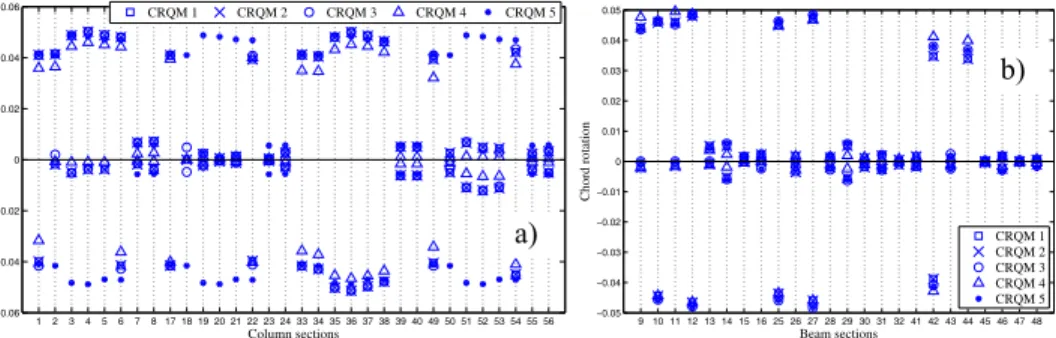
The performance of the CRQMs 1 to 5 obtained from pushover analyses is illustrated in Figs. 4 and 5, for the LS of NC under the modal loading pattern and for the LS of DL under the uniform loading pattern, respectively. Based on Fig. 4, the results of the column sections obtained with the CRQMs 1 to 4 show a good agreement. On the contrary, results of CRQM 5 deviate from those of the remaining methods in some sections, exceeding significantly the chord rotation values in such cases. Similar findings were seen in other pushover analysis results associated to LSs involving larger earthquake intensities (i.e. the SD and the NC). In beam, all methods are in good agreement. Based on Fig. 5, the results of column sections indicate that CRQM 3 performs well when compared to CRQMs 1 and 2, while CRQMs 4 and 5 have the tendency to, respectively, under- and overestimate the chord rotation. For beams, the CRQMs 3 and 5 show a good performance when compared to CRQMs 1 and 2. On the other hand, CRQM 4 tends to underestimate the chord rotation in some cases. Similar trends were observed in the remaining pushover analysis results associated to the LS of DL. It was also observed that the CRQM 1 and 2 results are in good agreement for members where xLs definition issues were identified. The performance of the
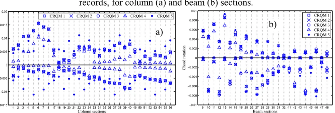
CRQMs 1 to 5 obtained from nonlinear dynamic analyses is illustrated in Figs. 6 and 7, for the LS of NC and one of the artificial records, and for the LS of DL and one of the ReLUIS records, respectively. The results obtained for these cases exhibit general trends similar to those obtained for the pushover analyses. By examining the results of each record, those obtained for the LSs of SD and NC indicate that, in some of the column sections, the CRQM 5 also yields results with larger deviations from those of the other methods, while, in beams, all methods continue to exhibit a good agreement. For the LS of DL, the results obtained for column sections indicate that CRQM 3 performs best, while the CRQMs 4 and 5 seem to under- and overestimate, respectively, the values of CRQMs 1 and 2.
In beams, the CRQMs 3 and 5 show a good performance, while CRQM 4 shows larger deviations, underestimating the chord rotation. After analyzing the results of CRQMs 3 to 5, it can be seen that CRQM 3 performs well, both in column and in beam sections, while CRQM 4 underestimates the chord rotation for the LS of DL since part of the member rotation is neglected by considering the plastic hinge contribution only. With respect to CRQM 5, this method overestimates the chord rotation in columns since the nodal rotation contribution is not considered. On the other hand, its good performance in beams indicates that the gravity loading influence can be neglected without a significant loss of accuracy.
1 2 3 4 5 6 7 8 17 18 19 20 21 22 23 24 33 34 35 36 37 38 39 40 49 50 51 52 53 54 55 56 −0.06 −0.04 −0.02 0 0.02 0.04 0.06 Column sections Chord rotation CRQM 1 CRQM 2 CRQM 3 CRQM 4 CRQM 5 9 10 11 12 13 14 15 16 25 26 27 28 29 30 31 32 41 42 43 44 45 46 47 48 −0.05 −0.04 −0.03 −0.02 −0.01 0 0.01 0.02 0.03 0.04 0.05 Beam sections Chord rotation CRQM 1 CRQM 2 CRQM 3 CRQM 4 CRQM 5
Figure 4: Performance of several CRQMs for the LS of NC considering pushover analysis with modal loading pattern, for column (a) and beam (b) sections.
b)
1 2 3 4 5 6 7 8 17 18 19 20 21 22 23 24 33 34 35 36 37 38 39 40 49 50 51 52 53 54 55 56 −0.015 −0.01 −0.005 0 0.005 0.01 0.015 0.02 Column sections Chord rotation CRQM 1 CRQM 2 CRQM 3 CRQM 4 CRQM 5 −0.015 9 10 11 12 13 14 15 16 25 26 27 28 29 30 31 32 41 42 43 44 45 46 47 48 −0.01 −0.005 0 0.005 0.01 0.015 0.02 Beam sections Chord rotation CRQM 1 CRQM 2 CRQM 3 CRQM 4 CRQM 5
Figure 5: Performance of several CRQMs for the LS of DL considering pushover analysis with the uniform loading pattern, for column (a) and beam (b) sections.
1 2 3 4 5 6 7 8 17 18 19 20 21 22 23 24 33 34 35 36 37 38 39 40 49 50 51 52 53 54 55 56 −0.06 −0.04 −0.02 0 0.02 0.04 0.06 0.08 Column sections Chord rotation CRQM 1 CRQM 2 CRQM 3 CRQM 4 CRQM 5 −0.04 9 10 11 12 13 14 15 16 25 26 27 28 29 30 31 32 41 42 43 44 45 46 47 48 −0.03 −0.02 −0.01 0 0.01 0.02 0.03 0.04 0.05 Beam sections Chord rotation CRQM 1 CRQM 2 CRQM 3 CRQM 4 CRQM 5
Figure 6: Performance of several CRQMs for the LS of NC considering one of the artificial records, for column (a) and beam (b) sections.
1 2 3 4 5 6 7 8 17 18 19 20 21 22 23 24 33 34 35 36 37 38 39 40 49 50 51 52 53 54 55 56 −0.015 −0.01 −0.005 0 0.005 0.01 0.015 0.02 Column sections Chord rotation CRQM 1 CRQM 2 CRQM 3 CRQM 4 CRQM 5 −0.01 9 10 11 12 13 14 15 16 25 26 27 28 29 30 31 32 41 42 43 44 45 46 47 48 −0.008 −0.006 −0.004 −0.002 0 0.002 0.004 0.006 0.008 0.01 Beam sections Chord rotation CRQM 1 CRQM 2 CRQM 3 CRQM 4 CRQM 5
Figure 7: Performance of several CRQMs for the LS of DL considering one of the ReLUIS records, for column (a) and beam (b) sections.
6. CONCLUSIONS
An application of the EC8-3 assessment procedures for RC structures was presented. The practical quantification of the member chord rotation according to EC8-3 was examined in detail along with several simplified alternative formulations. The performance of the several CRQMs was analyzed for a RC example structure, considering static and dynamic nonlinear analysis methods, and for earthquake intensity levels associated to the EC8-3 LSs. The comparison of the different CRQMs led to the following recommendations:
b) a) b) a) b) a)
• With respect to the use of the theoretical approaches with the alternative proposals of Section 3.1, CRQM 1 is preferred since it leads to results that are more regular and less sensitive to numerical issues than those of CRQM 2;
• With respect to the approximate CRQMs (i.e. those defined in Section 3.2), CRQM 3 is recommended since it showed the best overall performance in columns and beams. CRQM 3 is simple to compute after running the analyses (post-processing stage) as long as the nodal displacements are stored at each step during the analyses;
Acknowledgements
Financial support of the Portuguese Foundation for Science and Technology, through the PhD grant of the first author (SFRH/BD/32820/2007), are gratefully acknowledged.
References
[1] ATC 40 1996. Seismic Evaluation and Retrofit of Concrete Buildings. California: Applied Technology Council.
[2] FEMA 310 1998. Handbook for the Seismic Evaluation of Buildings - A Prestandard. National Earthquake Hazard Reduction Program. Washington DC: Federal Emergency Management Agency.
[3] FEMA 356 2000. Prestandard for the Seismic Rehabilitation of Buildings. American Society of Civil Engineers. Washington DC: Federal Emergency Management Agency. [4] ENV 1998-3 2005. Eurocode 8: Design of structures for earthquake resistance - Part 3:
Assessment and retrofitting of buildings. European Committee for Standardization. [5] Norme tecniche per il progetto, la valutazione e l’adeguamento sísmico degli edififi
2005. Ordinanza 3431, Anexo 2. Governo Italiano; (in Italian).
[6] Mpampatsikos, V, Nascimbene, R, Petrini, L 2008. A critical review of the R.C. frame existing building assessment procedure according to Eurocode 8 and Italian Seismic Code. Journal of Earthquake Engineering; 12(S1): 52-82.
[7] CEB 1996. RC frames under earthquake loading. Bulletin no.231, Comité Euro-International du Béton.
[8] Filippou, FC, Fenves, GL 2004. Methods of analysis for earthquake-resistant structures. In: Bozorgnia, Y., Bertero, VV (Eds.), Earthquake Engineering: From Engineering Seismology to Performance-based Engineering, CRC, Boca Raton.
[9] Carvalho, EC, Coelho, E, Campos-Costa, A 1999. Preparation of the full-scale tests on reinforced concrete frames - Characteristics of the test specimens, materials and testing conditions. ICONS report, Innovative Seismic Design Concepts for New and Existing Structures, European TMR Network, LNEC, Lisbon.
[10] Varum, H 1997. Numerical model for the seismic analysis of reinforced concrete plane frames. MSc Thesis, Fac. of Eng. of the Univ. of Porto, Porto, Portugal (in Portuguese). [11] Arêde, A. and Pinto, AV 1996. Reinforced concrete global section modelling:
definition of skeleton curves. Special Publication No.I.96.36. JRC, Ispra, Italy.
[12] Primi elementi in material di criteri generali per la classificazione sismica del territorio nazionale e di normative tecniche per le costruzioni in zona sismica 2003. Ordinanza 3274. Governo Italiano; (in Italian).
[13] Iervolino, I., Maddaloni, G., Cosenza, E 2008. Eurocode 8 compliant real record sets for seismic analysis of structures. Journal of Earthquake Engineering; 12(1): 54–90.