YIC2012 — Universidade de Aveiro First ECCOMAS Young Investigators Conference A. Andrade-Campos, N. Lopes, R.A.F. Valente, H. Varum (editors)
24–27 April 2012, Aveiro. Portugal.
Fire resistance of steel members protected with intumescent coatings
L. Mesquita
a,*, P. Piloto
a, S. Roque
a, M. Vaz
ba IPB- Polytechnic Institute of Bragança
Campus Sta Apolonia Apartado 1134 5300-857 Bragança, Portugal
b FEUP- Faculty of Engineering of the University of Porto
Rua Dr. Roberto Frias, s/n 4200-465 Porto, Portugal
*Corresponding author: lmesquita@ipb.pt
Abstract. The required intumescent coating thicknesses needed for fire resistance are proposed by the paints manufactures based on the results of a limited number of standard fire resistance tests, considering different steel section factors and DFTs. This work presents a set of 50 experimental fire resistance tests made in a pilot gas furnace and considering: (i) different member cross-sections (IPE, SHS, CHS, LNP), (ii) analysis at ambient temperature and fire conditions, (iii) application of a mechanical loading in a tree-point bending setup, (iv) different utilization degree level (30%, 50%, 70%) and (v) different
intumescent thicknesses.Results show that increasing intumescent fire protection thickness an increase in fire resistance time
is achieved. For the same nominal protection thickness the critical temperature and fire resistance time decreases with increasing degree of utilisation. The results from the unprotected fire tests are compared with the ones obtained by the Eurocode 3 part 1.2 simplified calculation method.. Taking into account the nominal properties only the CHS section experimental results shows unsafe fire resistance times in comparison to the Eurocode values.
Keywords:Fire resistance, Fire tests, Fire Protection, Intumescent Paint.
1 INTRODUCTION
Steel structures are widely used in building construction due to its high mechanical strength, ductility and execution times. However, due to deterioration of mechanical properties with temperature, it is essential that the whole structure and its elements have the necessary fire resistance to prevent a collapse caused by fire.
One of the measures used to design a structure with the required fire resistance but without applying any fire resistance material is to use higher cross-section elements, better quality steels or fire resistance steels. The alternative is the application of passive fire protection systems such as concrete, plaster boards, mineral fibbers or intumescent paints.
When protected, the steel temperature rise is mainly due to the conduction heat transfer mode, since the steel is not directly exposed to radiation from the fire or in contact with the surrounding gases (Lewis, KR, 2000). The application of intumescent coatings as fire protection depends on its physical and thermal properties, member section factor and the required fire resistance time. An increase of the fire resistance time can be achieved applying higher intumescent dry film thickness (DFT), or for the same DFT using sections with smaller section factors.
measures. Its application in the erection phase is only possible with good weather, causing interruptions in erection which might lead to an increase in the total cost of fire protection.
To reduce the total cost of fire protection through the application of thin film intumescent paints Longton et al [1] conducted a study focused on paint formulation and properties needed to be applied off-site and go to the site in the same day of coating. This can be achieved with reduced cure time coatings, improved durability, and resistance to damage during transport and erection. Extra care is needed when the damage put the steel visible since the tests show that, in these cases, the damage remains uncovered after intumescence and that there is no lateral expansion.
The need to develop environmentally friendly paints compelled paints manufactures to produce water-based intumescent paints with a significant reduction of volatile organic compounds (VOC). These have faster drying times and supports thicker coats, being more versatile than the solvent-based, resulting in surfaces of higher hardness, minimizing the damage caused by handling of protected elements.
The growing demand of fire protection measures and materials require the knowledge of the behaviour of this passive fire protection material. The intumescent fire reaction is responsible for an increase in the thermal resistance, increasing the fire resistance time of protected members. Thus the material thermal behaviour and efficiency influences the overall thermo-mechanical behaviour of structural elements under fire conditions. The current methodology for fire design prescribed in the European standard [2], see Equation (1), does not take into account the material increasing thickness or the thermal and physical properties variation with temperature, not describing the real fire behaviour.
0 0 ; 1 3 110
g S g
p s s S g p p
S t e T T e T
d c T T V A k T (1)
In previous equation cppdp css
V Ap
and t30s for protected steel elements. This equation is basedon the differential heat conduction equation solution with non-homogeneous boundary conditions and admits several simplifying assumptions. These assumptions constrain its application to materials with temperature
independent properties, as is the case of gypsum boards, mineral fibres and vermiculite. In equation (1) Ts,
represents the increase in steel temperature when submitted to an external temperature variation, based on
standard fire curves, Tg. When considering materials with thermal and physical temperature dependent
properties an update is mandatory mainly on the thermal conductivity and protection thickness during the fire
action, introducing p(t) and dp(t) over time or with the intumescent mean temperature.
For elements subjected to fire conditions whose resistance is directly proportional to the steel yield strength, the
critical temperature can de determined by the degree of utilization, 0, see equation (2). In other cases, elements
subjected to instability phenomena, an iterative procedure must be used.
482 ln 19 , 39 , 1 0,9674 1 0 3,833 cr a (2)
For a particular design the minimum coating thickness of protection is normally recommended by the paints manufacturers and presented in tables or graphs for different critical temperatures, section factors and different fire resistance periods, see Figure 1. These data are based on the fire resistance test results performed in fire resistance furnaces of certified laboratories using structural elements (beams and columns), with and without mechanical load. The results are usually kept confidential due to the coatings manufactures commercial nature, which limit a full characterization of the intumescent physical and thermal properties.
Recent studies on passive fire protection materials present analytical results of temperature evolution of protected materials based on simplified differential equations [3-7]. In these formulae the protection layer thickness variation are not considered.
than the measured temperature in the equivalent solid beams. The author justifies this difference due to intumescence shrinkage around the hole perimeter, but he also refers the lack of protection within the holes, consistent with a deficient coating.
0 20 40 60 80 100 120
0 50 100 150 200 250 300 350 Section Factor Ap/V [m-1]
Fire Resistance [min.]
dp1 dp2 dp3 dp4
Protection Thickness dp1<dp2<dp3<dp4
Figure 1 – Fire protection thicknesses for different fire resistance times and section factors.
Han et al [9] tested a solvent based intumescent coating applied to steel plates protected with dry film thicknesses from 0.3 to 1.2 [mm] and exposed to different radiative heat fluxes in a cone calorimeter. When a heat flux of 50 [kW/m2] is applied and for protection thicknesses higher than 0.5 [mm] the intumescence expansion ratio decreases, indicating that, for this thermal action, the protection is not fully decomposed into a carbonised material.
The aim of this work is to present a study made on steel elements protected with intumescent coatings. The protection efficiency is analysed considering elements with different cross sections (IPE, CHS, SHS and LNP), different utilization degrees (30%, 50% and 70 %) and protection thicknesses. The fire resistance tests are made in a fire resistance furnace under constant mechanical load and thermal conditions as prescribed by standard fire curve [10].
2 MATERIAL PROPERTIES CHARACTERIZATION
The steel mechanical properties was determined by tensile tests made on machined specimens obtained from the web, in the case of IPE, from the largest leg, in the case of angles and away from the weld for the tubular profiles. For each profile type at least three tensile tests were carried out according to the standard NPEN10002-1 [11]. The
results aim to determine the value of the modulus of elasticity, E, the proof stress at 0.2% of deformation, Rp,0.2%,
upper and lower yield strength, ReH, ReL, tensile strength, Rm, and total deformation at rupture, At.
shows the comparison between experimental results and nominal values for each section and steel grade, where the yield strength was considered equal to the averaged upper yield strength, except for the CHS section in which was considered the 0.2% proof strength. With the exception of this section, the average yield stress of the remaining sections is higher than the nominal value.
Table 1 – Comparison between nominal and experimental geometric and material properties.
A [mm2]
x102
Iz [mm4]
x104
Iy [mm4]
x104
It [mm4]
x104
Iw [mm6]
x109
y pl
W , [mm3]
x103
fy [MPa]
Nom 10,30 15,9 171,00 1,20 0,35 39,40 275
IPE
Real 10,59 15,35 177,85 1,28 0,35 40,46 302,47
Nom 11,40 12,70 12,3 2,42 1,40 30,68 275
L
Real 11,36 14,07 12,99 2,82 1,56 32,21 311,22
Nom 15,20 236,30 236,30 55,33 235
SHS
Real 16,11 249,70 249,70 58,24 352,00
Nom 12,41 145,00 145,00 37,80 235
CHS
Cross section dimensions were measured in several sections along elements length for each cross section type. Average values were used to determine geometric properties needed for plastic resistance design and lateral torsional buckling design accordingly to the member collapse mode, and later real degree of utilisation update, see Table 1 and Table 4.
3 EXPERIMENTAL SETUP AND ELEMENT INSTRUMENTATION
The conventional method of determining fire resistance of protected and unprotected structural elements is by standard fire tests. This test consists into determine the time in which the element continues stable when supports a mechanical load, usually constant, and a thermal load defined by a prescribed standard fire curve. Fire resistance is defined by the time elapsed from the beginning of the heating until the element can not support the load and its collapse is close.
The set of experimental tests performed at the Polytechnic Institute of Bragança to evaluate the behaviour of beams in fire and assess the protection thickness and utilization degree influence is the presented in Table 2. For comparison and determination of the load capacity (collapse load) tests were also done in elements at room temperature and in fire without fire protection. The test consists into determine the load bearing element capacity, i.e., the element ability to support the test load and maintaining its stability when exposed to fire without exceeding a specified criteria, usually based on the deflection and/or deflection rate.
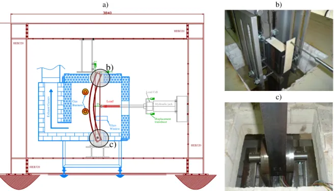
The fire furnace has interior dimensions of 1x1x1 [m3], insulated with refractory bricks and ceramic fibber. Is a
gas furnace with four gas burners in which the temperature evolution follows the specifications of the standard EN1363-1 [10] and is controlled by a plate thermocouple, see Figure 2.
The elements are subjected to a constant mechanical load and subsequent fire action accordingly to ISO834 standard fire curve, determining for each degree of utilisation and fire protection thickness the corresponding critical temperature and fire resistance time. The elements have a total length (Lt) of 1370 [mm], a length between supports (L) of 1210 [mm] and a length exposure to fire (Lf) equal to 1000 [mm].
a) b)
c) D
HEB320 HEB320
HEB320
HEB320
E
x
ha
us
t G
ass
es
Gas Burners
Glass Window
Hydraulic jack Load Cell
Load DV
DH
Displacement transducer
Figure 2 – a) Experimental test setup. b) Upper fork support. c) Lower end pined support.
b)
Table 2 – Experimental tests set and results.
dp
m EC3 Resist. Exp. Resist.Section Test nº Ap/V [m-1
] Fire
Cond 0
Q
[kN] DFT Std.dev. Max. Min. T [ºC] t [s] T [ºC] t[s]
I1 387 RoomT. - 31,84* - - - -
-I2 387 RoomT. - 31,84* - - - -
-I3 387 ISO834 30% 5,34 - - - - 663,78 745,56 751,20 1156
I4 387 ISO834 50% 9,18 - - - - 584,67 562,96 684,47 749
I5 387 ISO834 70% 12,94 - - - - 525,78 473,19 659,01 632
I6 387 ISO834 30% 5,34 974 193 1253 445 663,78 - 722,71 2505
I7 387 ISO834 30% 5,34 975 170 1287 576 663,78 - 727,57 2570
I8 387 ISO834 50% 9,18 1012 185 1342 560 584,67 - 701,02 2331
I9 387 ISO834 50% 9,18 1055 202 1528 490 584,67 - 701,88 2467
I10 387 ISO834 70% 12,94 998 148 1268 653 525,78 - 695,31 2341
I11 387 ISO834 70% 12,94 989 193 1360 501 525,78 - 690,21 2295
I12 387 ISO834 50% 9,18 1824 156 2140 1440 584,67 - 676,52 2867
IP
E 10
0
S2
75
I13 387 ISO834 50% 9,18 1832 194 2270 1440 584,67 - 747,46 3127
S1 250 RoomT. - 42,98* - - - -
-S2 250 RoomT. - 42,98* - - - -
-S3 250 ISO834 30% 13,62 - - - - 663,78 766,13 722,56 1032
S4 250 ISO834 50% 22,25 - - - - 584,67 583,56 641,95 693
S5 250 ISO834 70% 30,09 - - - - 525,78 492,36 594,02 573
S6 250 ISO834 30% 13,62 1105 115 1310 854 663,78 - 687,79 2444
S7 250 ISO834 30% 13,62 1094 113 1338 777 663,78 - 685,53 2411
S8 250 ISO834 50% 22,25 1141 100 1309 944 584,67 - 617,08 2060
S9 250 ISO834 50% 22,25 1141 104 1350 909 584,67 - 608,73 2047
S10 250 ISO834 70% 30,09 1144 114 1482 886 525,78 - 555,69 1812
S11 250 ISO834 70% 30,09 1131 92 1270 854 525,78 - 562,24 1836
S12 250 ISO834 50% 22,25 1932 112 2210 1730 584,67 - 651,64 1967
SH
S 100
x10
0x4
S23
5
S13 250 ISO834 50% 22,25 1933 144 2310 1700 584,67 - No Collapse
C1 246,9 RoomT. - 29,37* - - - -
-C2 246,9 RoomT. - 29,37* - - - -
-C3 246,9 ISO834 30% 9,31 - - - - 663,78 769,61 602,27 540
C4 246,9 ISO834 50% 15,20 - - - - 584,67 587,01 499,42 376
C5 246,9 ISO834 70% 20,56 - - - - 525,78 495,56 255,64 164
C6 246,9 ISO834 30% 9,31 997 114 1270 800 663,78 - 560,26 1414
C7 246,9 ISO834 30% 9,31 1004 111 1187 818 663,78 - 562,23 1861
C8 246,9 ISO834 50% 15,20 1026 143 1330 770 584,67 - No Collapse
C9 246,9 ISO834 50% 15,20 1006 93 1140 810 584,67 - 472,24 1144
C10 246,9 ISO834 70% 20,56 1071 143 1306 754 525,78 - 169,12 146
C11 246,9 ISO834 50% 20,56 1120 178 1439 785 525,78 - 490,75 1411
C12 246,9 ISO834 50% 15,20 1896 200 2190 1490 584,67 - 563,47 1378
C
H
S 10
1,
6
x
4
,05
S
2
3
5
C13 246,9 ISO834 50% 15,20 1807 210 2270 1430 584,67 - 512,00 1261
L1 250 RoomT. - 21,69* - - - -
-L2 250 RoomT. - 21,69* - - - -
-L3 250 ISO834 30% 5,84 - - - - 663,78 766,13 822,55 1743
L4 250 ISO834 50% 9,83 - - - - 584,67 583,56 761,68 1297
L5 250 ISO834 70% 13,61 - - - - 525,78 492,36 745,66 1210
L6 250 ISO834 30% 5,84 1041 91 1205 898 663,78 - 983,42 4692
L7 250 ISO834 30% 5,84 1026 107 1309 850 663,78 - 1015,19 4655
L8 250 ISO834 50% 9,83 1053 108 1318 898 584,67 - 747,38 3382
L9 250 ISO834 50% 9,83 1063 96 1271 825 584,67 - 760,49 3533
L10 250 ISO834 70% 13,61 1135 118 1420 882 525,78 - 756,97 3801
LN
P 10
0x50
x8
S275
L11 250 ISO834 70% 13,61 1114 110 1377 953 525,78 - 600,68 1937
The mechanical load corresponds to a predetermined degree of utilization in bending where the design fire
resistance at time t=0, Rfi,d,0, was based in the lateral torsional buckling resistance moment, for the sections IPE
The load is applied via an hydraulic jack with a load cell at its end. Its value depends on the desired degree of utilisation and is applied incrementally until it reaches the requested value and kept constant during the fire action. Steel temperature are measured by thermocouples type K welded to the steel profile in three sections along its length, and in these at different cross section points, as specified in the standard prEN13381-8 [12] and represented in Figure 3. As the standard does not specify the thermocouples location for angle sections the distribution adopted was the presented in Figure 3. The thermocouple wires are protected with a small steel angle (9x9 [mm]) to avoid exposure to temperatures higher than the ones at measuring points.
Bottom (B)
Top (T) Rigth(R)
S1 S2 S3 MR T ML B MR T ML B MR T ML B MR T ML B MR T ML B MR T ML B 36 36 36 BR T M BL BR T M BL B R T M BL TR
TL M BL
BR
TR
TL M BL
BR TR TL M BL BR L = 12 10 Lt = 1 370 L/3 200 L/3
Figure 3 – Thermocouple locations for measuring steel temperatures.
Additionally the top element horizontal (HD) and vertical (DV) displacements were measured by two LVDT and the mid-span displacement (D) at the load application point using wire potentiometric transducers.
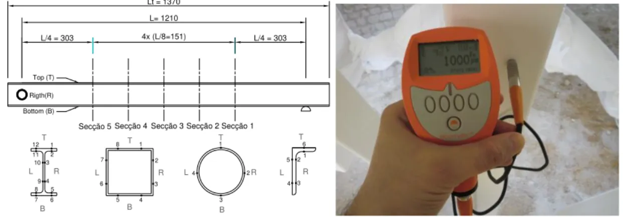
The elements were spray painted following the manufacturer's recommendations, presented in the data sheet, applying several coats and controlling its thickness using a wet film thickness gauge. After coating, the elements were conditioned under controlled temperature (23 ° C) and humidity (50%) for 8 days. Following this curing time the dry film thickness was measured in five sections in the element length and at the points indicated in Figure 4, complying with the prEN 13381-8 [12] requirements.
12 1 2 3 4 5 6 7 8 9 10 11 Bottom (B) Top (T) Rigth(R) L= 1210 Lt = 1370
L/4 = 303 4x (L/8=151) L/4 = 303
1 2 3 4 5 6 7 8 1 2 3 4 1 2 3 4 5 6
Secção 5 Secção 4 Secção 3 Secção 2 Secção 1
B T L R B T L R B T L R T L R
Figure 4 – Cross section thickness measuring points locations. Dry film thickness measuring device.
Table 2 shows the fire protection characterization, where the mean arithmetic dry film thickness, standard deviation, maximum and minimum measured values are presented.
4 COLLAPSE CRITERIA AND FIRE RESISTANCE
the end of heating or until it fails to meet the load bearing capacity criterion, whichever occurs sooner. The standard EN 1363-1 [10] specifies a failure criteria for columns and beams. For the first type of elements failure occurs when both the following criteria have been exceeded: (i) vertical contraction, C = h/100 [mm] and (ii) rate
of vertical contraction, dC/dt = 3h/1000 [mm/min], where h is the initial column height in [mm]. Beams are
deemed to have failed when both of the following criteria are exceeded: (i) deflection of L2/400d and (ii) rate of
deflection = L2/(9000d) [mm/min]. The rate of deflection limit shall not apply before a deflection of L/30 is
exceeded.
When the British Standard is used [13-14] the criteria is slightly different. For beams failure is defined by: (i)
deflection of L/20 or (ii) rate of deflection of L2/(9000d) [mm/min], whichever is exceeded first. L is the span of
the element (in mm) and d is the distance from the top of the structural section to the bottom of the design tension zone (in mm). Also the rate of deflection limit shall not apply before a deflection of L/30 is exceeded.
The standard EN 1363-1 differs from the BS 476 since it requires both a deflection limit and a deflection rate limit to be exceeded for failure, while in BS 476 failure occurs when if either criterion is exceeded. This implies that applying the BS 476 criteria leads to the same or a more conservative failure time and temperature [15].
For the studied sections, with d=100 [mm], the deflection limit criteria occurs when D=36.6 [mm], giving a displacement equivalent to L/33. From the analyses of time vs mid-span displacement curves one can see that the rate of deflection criteria is reached before the deflection of L/30 is exceeded, so the fire resistance is established by the time (rounded down to the nearest minute) when the deflection is equivalent to L/30.
5 ROOM TEMPERATURE TESTS RESULTS
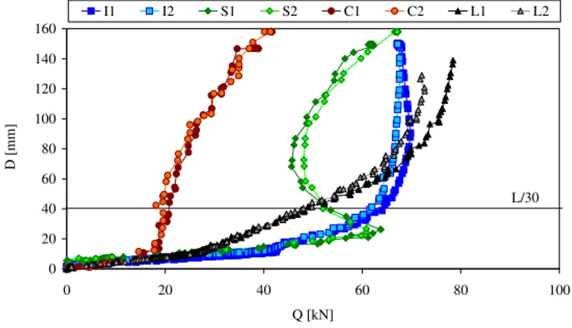
The load bearing capacity at room temperature was determined experimentally performing two tests in each cross section. The load was applied incrementally until the element leaves to support the load resulting in a large deformation. The load vs displacement curves presented in Figure 5 show a typical collapse mode due to instability phenomenon by lateral torsional buckling in IPE and angles sections and a mid span plastic hinges in SHS and CHS elements. Considering these collapse modes and for fire resistance comparison proposes, the load capacity was defined as the applied load when an equivalent displacement of L/30 was reached, in the cases of IPE and angles elements, and the maximum load at time when the plastic hinge is detected. The values are presented in Table 3 and compared with the results obtained from the Eurocode 3 part 1.2 [2] using the specified collapse mode formulae and the nominal and real values of the yield strength and cross section dimensions.
0 20 40 60 80 100 120 140 160
0 20 40 60 80 100
Q [kN]
D [m
m]
I1 I2 S1 S2 C1 C2 L1 L2
L/30
Figure 5 - Load vs displacement curves at room temperature.
6 EXPERIMENTAL TESTS IN FIRE WITHOUT FIRE PROTECTION
of unprotected elements gives a fire resistance time of 12, 9 and 7 minutes for the IPE100 section, respectively,
and for the remaining sections, with section factors close to 250 [m-1], a fire resistance of 12, 9 and 8 minutes, see
Table 2 and Table 4. These values can be compared with experimental results, in time and temperature domains, where the collapse criteria were based on the L/30 equivalent displacement, as stated before.
Table 3 – Comparison between the experimental results and the one obtained by the Eurocode 3 part 1.2.
Resistance EC3-1.1
Section Test nº
Nom. Real
exp
Q
L/30 [kN]
exp
Q
Max [kN]
Collapse mode
I1 31,84 34,99 64,22 69,82 LTB
IPE 100
I2 31,84 34,99 61,76 67,78 LTB
S1 42,98 66,23 53,11 63,73 Plast. hinge
SHS
S2 42,98 66,23 52,01 67,19 Plast. hinge
C1 29,37 22,76 20,78 38,91 Plast. hinge
CHS
C2 29,37 22,76 18,70 41,61 Plast. hinge
L1 21,69 25,45 48,78 78,44 LTB
LNP
L2 21,69 25,45 48,06 72,67 LTB
Table 4 – Critical temperature and fire resistance time comparison between Eurocode and unprotected experimental tests.
Degree of Utilisation% Tcr-EC3 [ºC] Time-EC3 Tcr-Exp. [ºC] / Time [min]
Nom 30 50 70 663,78 584,67 525,78 12 9 7
IPE
Real 29,17 47,71 64,38 668,02 592,17 541,72 12 9 8 751,20/19 684,47/12 659,01/10
Nom 30 50 70 663,78 584,67 525,78 12 9 8
SHS
Real 20,10 32,82 44,40 724,15 659,07 610,82 17 12 10 722,56/17 641,95/11 594,02/9
Nom 30 50 70 663,78 584,67 525,78 12 9 8
CHS
Real 40,89 66,77 90,32 625,45 536,21 443,98 11 8 6 602,27/9 499,42/6 255,64/2
Nom 30 50 70 663,78 584,67 525,78 12 9 8
L
Real 29,17 47,71 64,38 668,02 592,17 541,72 12 9 8 822,55/29 761,68/21 745,66/20
The results presented in Table 2 and Table 4 show that the critical temperature and the fire resistance time obtained from the IPE and LNP cross sections are higher than the ones determined from the Eurocode 3 part 1.2, despite the degree of utilisation. The critical temperature and fire resistance are inversely proportional to the degree of utilisation applied in the element. Regarding the SHS and CHS sections the results from Eurocode 3 Part 1.2 are higher than those obtained experimentally, with a maximum difference of one minute fire resistance for the SHS. For the CHS the difference between both methods increases with the degree of utilisation, even comparing with the real geometric and material properties.
Figure 6 presents the steel temperature evolution with time considering the arithmetic mean of all thermocouples in the three measuring sections.
7 EXPERIMENTAL TESTS IN FIRE WITH FIRE PROTECTION
a) b)
c) d)
Figure 6 – Experimental steel temperature evolution and mid span displacement results of members without fire protection. a) IPE sections. b) SHS sections. c) CHS sections. d) LNP sections.
Figure 7 – Intumescence development and final state of test I7.
The fire tests results of members protected with intumescent coating are presented in Figure 10, where they can be compared with the tests results of members without fire protection. The temperatures presented are mean values of all measured temperatures in the element. The temperature behaviour of IPE sections show a clear distinction
between the elements protected with nominal DFT of 1000
m and 2000
m , and there is no clear influenceof the degree of utilisation on the temperature evolution. For SHS and CHS sections the influence of the protection thickness on the coating performance is only clear for short exposure times. When these elements are
protected with 2000
m nominal DFT, with increasing exposure times and the consequent intumescence charexpansion there is a partial detachment, and sometimes total detachment, leaving the steel with a reduced fire protection or even with no protection at all. This becomes less favourable in comparison to thicknesses of 1000
m , resulting in higher steel temperatures. Due to the high load bearing capacity of the LNP sections with autilisation of 50%, tests with higher thicknesses were not done.
Figure 8 – Local shrinkage of test C9. Figure 9 – Local shrinkage of test L11.
Critical temperature and fire resistance time were determined by the collapse criterion, which corresponds to the steel temperature and the time when the mid span displacement is equivalent to L/30. The numerical values are presented in Table 2 and the displacement time evolution, for protected and unprotected elements, presented in Figure 11. The figure shows the protection efficiency by increasing fire resistance time when compared to the equivalent unprotected element and same degree of utilisation. In the case of C9 and L11 tests this increase was not as significant due to a local intumescence shrinkage that leaves the steel in direct contact to the fire hot gases, as can be seen in Figure 8 and Figure 9. As the real degree of utilisation of the sections CHS turns to be higher than the initially expected, e.g. the nominal 70% represents a real value of 90.32%, the C10 test reach the collapse criteria after only 146 [s], before the intumescent paint starts to react. Therefore the test C11 was tested with a degree of utilisation of 50%.
a) b)
0 200 400 600 800 1000
0 500 1000 1500 2000 2500 3000 3500 4000 4500 t [s]
T [º
C]
ISO 834 I3 I4 I5 I6 I7 I8 I9 I10 I11 I12 I13
Sem Prot I3-I5
dp1000 [m] I6-I11
dp2000 [m] I12-I13
0 200 400 600 800 1000
0 500 1000 1500 2000 2500 3000 3500 4000 4500
t [s]
T [ºC
]
ISO 834 S3 S4 S5 S6 S7 S8 S9 S10 S11 S12 S13
Sem Prot S3-S5
dp1000 [m] S6-S11 dp2000 [m] S12-S13
c) d)
0 200 400 600 800
0 500 1000 1500 2000 2500 3000
t [s]
T [º
C]
ISO 834 C3 C4 C5 C6 C7
C8 C9 C10 C11 C12 C13
Sem Prot C3-C5
dp1000 [m] C6-C11
dp2000 [m] C12-C13
0 200 400 600 800 1000
0 1000 2000 3000 4000 5000 6000
t [s]
T [ºC
]
ISO 834 L3 L4 L5 L6 L7 L8 L9 L10 L11
Sem Prot L3-L5
dp1000 [m] L6-L11
a) b)
0 20 40 60 80 100 120 140 160
0 500 1000 1500 2000 2500 3000 3500 4000 4500 t [s]
D
[mm]
I3 I4 I5 I6 I7 I8 I9 I10
I11 I12 I13
L/30
0 20 40 60 80 100 120 140 160
0 500 1000 1500 2000 2500 3000
t [s]
D [mm
]
S3 S4 S5 S6 S7 S8 S9
S10 S11 S12 S13
L/30
c) d)
0 20 40 60 80 100 120 140 160
0 500 1000 1500 2000 2500 3000 t [s]
D [
m
m]
C3 C4 C5 C6 C7 C8 C9 C10 C11 C12 C13
L/30
0 20 40 60 80 100 120 140 160
0 1000 2000 3000 4000 5000 6000 7000 t [s]
D [
m
m]
L3 L4 L5 L6 L7 L8 L9 L10 L11
L/30
Figure 11 – Experimental mid span displacement of members with and without fire protection. a) IPE sections. b) SHS sections. c) CHS sections. d) LNP sections.
8 CONCLUSIONS
To study the influence of the intumescent coating thickness, the degree of utilisation and the cross section type, a set of 50 tests were done in a fire resistance furnace using elements subjected to bending. Of these, and for comparison proposes, 8 were performed at room temperature and the others under fire conditions using the standard fire curve and nominal degrees of utilisation of 30%, 50% and 70% applied in protected and unprotected elements.
In the case of tests without fire protection a comparison is made between experimental results and the values obtained by the Eurocode 3 part 1.2 simplified method. Taking into account the nominal properties only the CHS section experimental results shows unsafe fire resistance times in comparison to the Eurocode values.
Increasing intumescent fire protection thickness an increase in fire resistance time is achieved. For the same nominal protection thickness the critical temperature and fire resistance time decreases with increasing the degree of utilisation. In the SHS and CHS protected sections a partial detachment and intumescence shrinkage was sometimes observed leaving steel with reduced protection or even unprotected.
ACKNOWLEDGMENTS
The authors acknowledge financial support from the Portuguese Science and Technology Foundation, project PTDC/EME-PME/64913/2006, “Assessment of Intumescent Paint Behaviour for Passive Protection of Structural Elements Submitted to Fire Conditions”, and fellowship SFRH/BD/28909/2006. The authors also acknowledge the contribution from the paints manufactures: CIN and Nullifire.
REFERENCES
applied intumescent coatings. 2005, European Commission: Luxembourg.
[2] EN1993-1-2, Eurocode 3: Design of Steel Structures, Part 1-2: General rules, Structural fire design. 2005, European Committee for Standardization
[3] Wong, M.B. and J.I. Ghojel, Sensitivity analysis of heat transfer formulations for insulated structural steel components. Fire Safety Journal, 2003. 38(2): p. 187-201.
[4] Tan, K.h., Z. Wang, and S.K. Au, Heat transfer analysis for steelwork insulated by intumescent paint exposed o standard fire conditions, in Third international Workshop Structures in fire. 2004: Ottawa.
[5] Silva, V.P.E., Determination of the steel fire protection material thickness by an analytical process - a simple derivation. Engineering Structures, 2005. 27(14): p. 2036-2043.
[6] Wang, Z.-H., S.K. Au, and K.H. Tan, Heat transfer analysis using a Green's function approach for uniformly insulated steel members subjected to fire. Engineering Structures, 2005. 27(10): p. 1551-1562.
[7] Wang, Z.H. and K.H. Tan, Sensitivity study of time delay coefficient of heat transfer formulations for insulated steel members exposed to fire. Fire Safety Journal, 2006. 41(1): p. 31-38.
[8] Bailey, C., Indicative fire tests to investigate the behaviour of cellular beams protected with intumescent coatings. FIRE SAFETY JOURNAL, 2004: p. 689-709.
[9] Han, Z., A. Fina, G. Malucelli, and G. Camino, Testing fire protective properties of intumescent coatings by in-line temperature measurements on a cone calorimeter. Progress in Organic Coatings, 2010. 69(4): p. 475-480.
[10] CEN, EN1363-1: Fire resistance tests. General requirements. 1999, European Committee for Standardization [11] IPQ, NP EN 10002-1: Materiais metálicos, Ensaio de tracção. Parte 1: Método de ensaio. 1990, Instituto
Português da Qualidade.
[12] prEN13381-8, Test methods for determining the contribution to the fire resistance of structural members. Applied reactive protection to steel members. 2007, European Committee for Standardization
[13] BS476-20, Fire tests on building materials and structures - Part 20: Method for determination of the fire resistance of elements of construction (general principles), in BS 476-20. 1987, CEN.
[14] BS476-21, Fire tests on building materials and structure — Part 21: Methods for determination of the fire resistance of loadbearing elements of construction, in BS 476-21. 1987, CEN.
[15] Gardner, L. and N.R. Baddoo, Fire testing and design of stainless steel structures. Journal of Constructional Steel Research, 2006. 62(6): p. 532-543.