FIRE PROTECTION DURABILITY OF INTUMESCENT
COATINGS AFTER ACCELERATED AGING
Rida Thabet
Final thesis submitted to the
School of Technology and Management
Polytechnic Institute of Bragança
For the fulfilment of the requirements for a Master’s Degree in
Industrial Engineering
Mechanical Engineering Branch
Supervisor at IPB:
Prof Dr. Luis Mesquita
Supervisor at UHBC:
Dr. Abdellah Benarous
ACKNOWLEDGEMENTS:
I start by thanking the God for having given us the courage, the will, the love of knowledge and above all patience in order to produce this modest work.
My deepest gratitude goes to my parents who supported me since my early days in school until this point. Also my brother Yazid and my sister Nadjet that I wish them success in their life and their studies without forgetting my cousin Ibrahim.
My first thanks go to my supervisor from the Polytechnic Institute of Bragança professor Luis Mesquita and professor Abdallah Benarous from University Hassiba Benbouali of Chlef that they give me the chance to realize this thesis in the best conditions.
I wish to thank all the teachers of the Mechanical Engineering Department who assured our training. Also my thanks to Eng. Luisa Barreira, technician of Laboratory of Structures and Strength of Materials (LERM) for her assistance in my experiments.
I also thank all my family, all my friends and all the students in my class, and I wish a better future for them.
Finally, my sincere thanks to all those who helped me. I say to them "thank you"
Resumo
O método mais comum de se obter a resistência ao fogo exigida é através da aplicação de sistemas de protecção passiva contra o fogo, sendo as tintas intumescentes um dos materiais de proteção contra incêndio frequentemente utilizados. Estes são normalmente considerados revestimentos finos na medida em que são aplicados com uma espessura de filme seco (DFT) entre 0,3-3 [mm]. A DFT necessária é obtida por meio de testes de resistência ao fogo experimentais realizados para avaliar a contribuição deste material reativo de proteção contra incêndio na resistência ao fogo dos elementos de aço. Estes testes são realizados após o revestimento seco e um curto período de tempo de condicionamento atmosférica, a temperatura e humidade constantes. À medida que a formulação de revestimentos é feita principalmente a partir de compostos de base poliméricos, é de esperar que os fatores ambientais, como temperatura, humidade e radiação UV (UVA e UVB) afetem de forma significativa o desempenho do revestimento intumescente de proteção contra incêndios e a sua durabilidade.
Este trabalho apresenta um estudo sobre os efeitos do envelhecimento no desempenho da proteção contra incêndio das tintas intumescentes. É utilizada uma tinta intumescente comercial, de base aquosa, submetida a um ciclo de envelhecimento acelerado, utilizando uma câmara QUV de envelhecimento acelerado. Este ciclo de envelhecimento acelerado pretende simular 10 anos de envelhecimento natural do material. A durabilidade e o seu desempenho de proteção ao fogo são comparados através da realização de testes realizados em calorímetro de cone antes e após o ciclo de envelhecimento.
Palavras-chave:
Abstract
The most common method of achieve the required fire resistance is by the use of passive fire protection systems, being intumescent coatings the fire protection material frequently used. These are usually considered thin film coatings as they are applied with a dry film thickness (DFT) between 0.3-3 [mm]. The required DFT is obtained by experimental fire resistance tests performed to assess the contribution of this reactive fire protection material to the steel member fire resistance. This tests are done after dry coating and a short time period of atmospheric conditioning, at constant temperature and humidity. As the coatings formulation is mainly made from polymeric basis compounds, it is expected that the environmental factors, such temperature, humidity and UV radiation (UVA and UVB) significantly affect the intumescent coating fire protection performance and its durability.
This work presents a research study about the effects of aging on the fire protection performance of intumescent coatings. A commercial water based coating is submitted to an accelerated aging cycle, using a QUV Accelerated Weathering Tester. This tests aim to simulate 10 years of the coating natural aging. The coating durability is tested comparing the fire protection of small steel samples submitted to a radiant heat flux exposure from a cone calorimeter. In total, 28 tests were performed on intumescent coating protected steel specimens, of which 14 specimens were tested before the hydrothermal aging test and other 14 after accelerated aging.
The experimental tests results of the steel temperature evolution shows that increasing the intumescent dry coating film thickness, the fire resistance time increases. After the accelerated aging cycles, the coating lose their ability to expand, resulting in an increase of the steel temperature of approximately 200 [ºC], compared to the samples without aging.
Keywords:
Index
ACKNOWLEDGEMENTS: ... I RESUMO ... III ABSTRACT ... V LIST OF FIGURES ... IX LIST OF TABLES ... XI SIMBOLOGY ... XIII
CHAPTER 1: INTRODUCTION ... 1
1.1 CONTEXT AND MOTIVATION ... 1
1.2 STATE OF THE ARTE ... 2
1.3 THESIS STRUCTURE ... 7
CHAPTER 2: REACTIVE COATINGS: CONDITIONING OF TESTS SPECIMENS AND TEST CONDITIONS ACCORDING TO THE “ETAG N°018” ... 9
2.1 INTRODUCTION ... 9
2.2 ENVIRONMENTAL CONDITIONS TO BE TESTED... 10
2.3 SPECIMENS TEST CONDITIONS ... 10
2.3.1 Test Procedure ... 11
2.4 BEHAVIOUR UNDER DIFFERENT ENVIRONMENTAL CONDITIONS ... 12
2.4.1 Exposure conditions for Type X: Reactive coating system intended for all conditions .. 12
2.4.2 Exposure conditions for Type Y: Reactive coating system intended for internal and semi-exposed conditions. ... 15
2.4.3 Exposure conditions for type Z1: Reactive coating system intended for internal conditions with high humidity. ... 16
2.4.4 Exposure conditions for type Z2: Reactive coating system intended for internal conditions ... 17
CHAPTER 3: CONE CALORIMETER EXPERIMENTAL TESTS ... 19
3.1 INTRODUCTION ... 19
3.2 PREPARATION OF THE SPECIMENS ... 20
3.3 EXPERIMENTAL SETUP ... 20
3.4 EXPERIMENTAL TESTS RESULTS WITHOUT AGING: ... 23
3.4.1 Heat release rate (HRR) ... 26
3.4.2 Mass loss... 27
3.4.3 Intumescence development ... 29
3.5 EXPERIMENTAL TESTS WITH AGING ... 31
3.5.1 Accelerated aging process ... 31
3.5.2 Cone calorimeter tests ... 35
CHAPTER 4: CONCLUSIONS AND FUTURE WORK ... 41
4.1 MAIN CONCLUSIONS ... 41
4.2 FUTURE LINES OF INVESTIGATION ... 42
REFERENCES ... 45
ANEXES ... 47
List of Figures
Figure 1: X1 exposure temperature and humidity according to EN ISO 4892-3:2006,
[12]. ... 13
Figure 2: X1 exposure UV lamp and water spray according to EN ISO 4892-3:2006, [12]. ... 13
Figure 3: Variation of Temperature for X and Y exposure during 2 weeks. ... 14
Figure 4: Variation of Humidity for X and Y exposure during 2 weeks. ... 15
Figure 5: Z1 exposure Temperature and Humidity. ... 16
Figure 6: Z2 exposure Temperature and Humidity. ... 17
Figure 7: Steel plate before and after coating. ... 20
Figure 8: Cone calorimeter and experimental setup. ... 21
Figure 9: Sketch of the component of cone calorimeter. ... 21
Figure 10: Coated steel plates, with fixed thermocouples. Tested samples at 35 [kW/m2] and at 75 [kW/m2]. ... 23
Figure 11: Measured temperature in the steel plates for a radiant heat flux of 75 [KW/m2]. a) ds= 14 [mm], b) constant nominal DFT= 1 [mm]. ... 24
Figure 12: Measured temperature in the steel plate for a radiant heat flux of 35 [KW/m2]. a) ds= 5 [mm], b) constant nominal DFT= 1 [mm]. ... 25
Figure 13: Heat release rate of the intumescent at 75 [KW/m2]. ... 27
Figure 14: Heat release rate of the intumescent at 35 [KW/m2]. ... 27
Figure 15: Measured mass loss with time at 75 [KW/m2]. ... 28
Figure 16: Measured mass loss with time at 35 [KW/m2]. ... 29
Figure 17: Intumescence expansion for a radiant heat flux of 75 [KW/m2]... 30
Figure 18: Intumescence expansion for a radiant heat flux of 35 [KW/m2]... 30
Figure 19: Intumescence expansion with time of test P5 at 75 [kW/m2]. ... 30
Figure 21: Position of specimens inside QUV Accelerated Weathering Tester. ... 33 Figure 22: Intumescent coating surface after hydrothermal aging test of two different dry
film thicknesses. ... 34 Figure 23: Intumescent coating surface after hydrothermal aging test of all specimens. ... 34 Figure 24: Coated steel plates after accelerated aging, with fixed thermocouples. Tested
samples at 35 [kW/m2] and at [75 kW/m2]. ... 35 Figure 25: Measured temperature in the steel plate for a radiant heat flux of 75 [kW/m2]
after hydrothermal aging test. a) ds= 14 [mm], b) constant nominal DFT= 1 [mm]. ... 36 Figure 26: Measured temperature in the steel plate for a radiant heat flux of 35 [kW/m2]
after hydrothermal aging test. a) ds= 14 [mm], b) constant nominal DFT= 1 [mm]. ... 37 Figure 27: Heat release rate variation of the intumescent coating at 75 [kW/m2]. ... 38 Figure 28: Heat release rate variation of the intumescent coating at 35 [kW/m2]. ... 38 Figure 29: Measured mass loss with time after hydrothermal aging test at 75 [kW/m2]. ... 39 Figure 30: Measured mass loss with time after hydrothermal aging test at 35 [kW/m2]. ... 39 Figure 31: Final intumescent char thickness of specimen S10. ... 40 Figure 32: Climate chamber. ... 42 Figure 33: Measured thermal conductivity of intumescent char before and after aging
using HotDisk. ... 43 Figure 34: Measured temperature in the steel plates for all tests at 35 [KW/m2]. ... 48 Figure 35: Measured temperature in the steel plates for all tests at 75 [KW/m2]. ... 48 Figure 36: Measured temperature in the steel plates for all tests at a radiant heat flux of
35 [KW/m2]. ... 49 Figure 37: Measured temperature in the steel plates for all tests at a radiant heat flux of
List of Tables
Table 1: Exposure conditions type X according to EN ISO 4892-3:2006, [12]. ... 12
Table 2: Exposure cycles type X. ... 14
Table 3: Exposure cycles type Y. ... 15
Table 4: Exposure cycles type Z1... 16
Table 5: Exposure cycles type Z2... 17
Table 6: Set of experimental testes. Reference: Heat flux/Steel Thick/Dry Thick/ Test N°. ... 22
Table 7: Steel substrate temperature at different times. ... 26
Simbology
DFT Dry Film Thickness.
ds Thickness of the steel plates. Pi Specimen i tested without aging.
Si Specimen i tested after hydrothermal aging. Ai Specimen i tested without protection. HRR Heat release rate.
Chapter 1:
Introduction
1.1 Context and motivation
Intumescent coating has been widely used as fire protection because it has such advantages as lightweight, attractive appearance and convenient construction. In countries such as the UK, the use of intumescent coating dominates the passive fire protection market, [1]. In china, fire resistant coating was only applied in large vessels at early stage. Passive fire protection market has been highly developed since 2000 and the intumescent coating has been widely used in large scale buildings such as departure lounge, stadium and exhibition hall in the past few years.
non-comprehensive and insufficient, which adversely affects safety and economy of fire resistance design of steel structure.
From the perspective of evolution in fire resistance design method, performance-based fire resistance design raised in the 90’s is the development trend in future. In the theory of performance-based design, research on fire load and temperature analysis as well as mechanical behaviour of steel structure is an important part. Due to the reactive nature of intumescent coating, insulation properties change under different fire exposure conditions. Study on fire retard performance of intumescent coating in natural fire especially in large-space fire is a key problem to be addressed.
Exposure to long term environmental conditions can cause intumescent coating to lose some of the reactive materials, thus reducing the effectiveness of the intumescent coating. Since fire safety requirement is throughout the entire life of a building structure which may last many tens of years. How to consider durability of intumescent coating is a new problem facing fire resistance design of steel structure.
1.2 State of the arte
by spreading 5 mm thick square steel plate sized 100 × 100 mm2. The coated plates were subjected to the torch flame gas whose temperature has increased in accordance with the standard temperature time curve (ISO 834). Three thermocouples were positioned on the rear face of the test plate and the rear plate temperatures were recorded. The time was defined as the time to fire resistant, if the average of these three temperatures reached 300° C. The dry film thickness of flame retardant coatings was 1 mm. As a result, aging has severely damaged the expanding effect and fire-resistant properties of flame-retardant coating. Nanometer titanium dioxide can improve the resistance of the coating to ultraviolet rays through its high UV ray absorption rate, and the nanoscale interpenetrating networks formed by well-distributed nanoparticles can improve the resistance of the coating to moisture through the “labyrinth” effect. Consequently, nano- coating can have the good expanding effect and fire-resistant property even after 500 h of accelerated aging, [2] .
and 42 cycles correspond to fresh coating, 2 years, 5 years and 20 years in service. After the specimens were subjected to hydrothermal aging, they were placed in a furnace and exposed to fire. The furnace temperature was regulated according to the ISO 834 standard temperature-time curve. Each test was continued until the steel temperature reached 700°C. The results obtained by Wang showed that compared to specimens without hydrothermal aging, after 42 cycles of hydrothermal aging (to simulate 20 years of exposure to an assumed exposure environment), the effective thermal conductivity of type-U intumescent coating was 50% higher and that of type-A intumescent coating 100% higher than that of the fresh coating. These increases in effective thermal conductivities resulted in increases in steel temperatures of up to 150 °C and 220 °C higher than the steel temperatures of the specimens without hydrothermal aging for the U intumescent coating and type-A intumescent coating specimens, respectively.
To delay the flame of polypropylene (PP), Xie et al [4] added an additive N-alkoxy multifunctional steric hindrance (NOR116) amine was combined with the polyphosfate of ammonium/pentaerythritol (APP/PER). The consequences of NOR116 on non-combustibility, ultraviolet Ray (UV), resistance to ageing and thermal degradation of the PP mixture / APP / PER have been studied by oxygen limiting (Act), vertical burning test (UL-94) color cone test (CCT), UV aging and thermogravimetric analysis (TGA) test. In this experiment, Xie use as materials N-alkoxy hindered amine (NOR116 yellow powder), Ammonium polyphosphate (APP), Pentaerythritol (PER) and Polypropylene (PP, T30S). All the materials were used directly without further purification.
tested the yellow index (YI) and the mechanical properties for every 5 days. The TGA was carried out on a thermogravimetry tester from 30 °C to 700 °C at a heating rate of 5, 10, 20 and 40 °C/min under a nitrogen flow of 40 mL/min. All samples were measured in an alumina crucible with a weight of about 10 mg.
The results obtained by Xie suggest that the addition of a small amount of NOR116 to APP/PER could effectively improve the flame retardancy, UV aging resistance and thermal stability of the PP/IFR mixtures. 0.5 wt% of NOR116 increase the LOI value of PP/IFR from 31% to 35% and also the temperature. The PP/IFR/NOR116 mixture obtain good mechanical properties than those of the PP/IFR mixture after 30 days of UV-light irradiation treatment. Ammonium polyphosphate (APP) is the most frequently used as acid source in intumescent coatings. It takes on about 30 wt% in the dry ingredients of the coating. APP yields inorganic acid when the fire resistive coating is exposed to flame. To see the influence of degree of polymerization of ammonium polyphosphate on anti aging property of waterborne fire resistive coatings, 5 kinds of ammonium polyphosphate (APP) with different degrees of polymerization (DP, DP = 5, 30, 78, 125, 184) were used as acid source in fire resistive coatings. After a period of accelerated aging tests, the influences of DP of APP on the anti-aging property of the coatings were investigated in detail by XPS, TGA, XRD, SEM and fire protection test. Results from the XPS showed that the migration speed of APP with higher DP from inside to outside of the coating was smaller during the aging process, which prevents the loss of APP and keep the intumescent performance of the coating. TGA and fire protection test results showed that the thermal stability and fire protection of the coating using APP with high DP could still maintain the excellent intumescent performances and fire protection. XRD results proved that the remaining APP could react with TiO2 to produce more ceramic TiP2O7 to protect the char layer. SEM observation indicated that the foam structure of the coating char layer would be better kept after being aged when APP of higher DP was adopted. Besides, the anti-oxidation property of the char layer would also be maintained. Therefore, the coating using APP with higher DP would more likely to keep the fireproof property after being aged, showing better anti-aging property, [6].
results. The measured results of intumescent coating expanded thickness and bubble size show that aging has two detrimental effects on the insulation performance of intumescent coating: reducing the expansion thickness and increasing the bubble size, both leading to increased thermal conductivity, [7].
Passive fire protection (PFP) coatings are widely used in the offshore industry and increasingly so for onshore applications. However, there are concerns that the performance of PFP systems in a fire may have deteriorated because of weathering and/or that corrosion of the protected item may be taking place beneath the PFP systems. To see the effects of weathering, six epoxy intumescent PFP products (Chartek III and IV, Firetex M90, Nullifire System E, Pitt-Char and Thermo-lag 440) and one cementitious PFP product (Mandolite 550) have been subjected to long term weathering at a maritime site. The results have been presented in terms of resistance to weathering, corrosion and fire and suggest that to have successfully resist to weathering, most PFP coatings require proper preparation of the substrate (cleaning, priming, key coat, etc.), and closely controlled application within the specified environmental range (temperature, humidity) with as smooth a finish as possible. Furthermore a proper treatment of edge features to prevent the interface becoming a corrosion site and, when necessary, to provide resistance to jet fires. The PFP need also a resilient topcoat suitable for exposed duty, qualified as part of the fire testing and accelerated weathering programmes, with timely renewal. In addition to adequate inspection, maintenance and repair, [8].
mechanisms from accelerated and natural aging shall be compared. A parameter to be investigated more in detail is the influence of the local dust composition that might lead to aggressive electrolytes in combination with water. The effect of different dust and sand types from North African desert regions on the reflectors durability shall be examined in future accelerated aging tests, [9].
Passive fire protection materials insulate steel structures from the effects of the elevated temperatures that may be generated during fire. They can be divided into two types, non-reactive, of which the most common types are boards and sprays, and reactive, being intumescent coatings an example. They are available as solvent or water based systems applied up to approximately 3[mm]. To assess the performance of water-based intumescent paints used as a passive fire protection material an experimental study was done. These tests were performed in a cone calorimeter as prescribed by the standard ISO5660, [5], in steel plates coated with two different paints, three dry film thicknesses and considering two different radiant heat fluxes. During tests, among other quantities, the steel temperature, the intumescence mass loss and thickness variation were measured. A numerical model is also presented to study the intumescence behaviour. The paint thermal decomposition numerical model is based on the conservation equation of energy, mass and momentum. For the steel temperature the numerical results follow reasonably well the experimental values. The major differences occur at intermediate times probably because a transition state of molten polymer was not considered. The determined steel temperatures and the moving front are strongly dependent on the activation energy that defines the amount of mass loss of virgin paint. It must be said that the value used in the simulations was obtained from the literature, but the correct value of both paints are needed. The reaction kinetics parameters can be obtained from thermogravimetric analysis, [10].
1.3 Thesis structure
This thesis consists, besides this introductory chapter that includes a general state of the art and the chapter of general conclusions, two main chapters.
Chapter 2:
Reactive Coatings: conditioning of
tests specimens and test conditions
according to the “ETAG N°018”
2.1 Introduction
European Technical Approval Guideline (ETAG N° 018) Part 2 “Reactive Coatings for fire protection of steel elements” specifies the terminology and definitions, the specific methods of verification and for identification. It also gives guidance on the installation instructions and for the Attestation of Conformity for these products, [3].
An ETA issued on the basis of this ETA-Guideline will cover reactive coatings or reactive coating kits to be used on steel elements. In each case, the ETA will cover at least the reactive coating layer (see Foreword). This ETA-Guideline can also be used as a basis for the assessment of cast iron. Properties that are independent of the substrate can be assessed with steel substrate (e.g. durability).
This ETA-Guideline does not cover: Factory-coated steel elements, where the ‘product’ is the element itself. Products placed on the market in the form of prefabricated, preformed shells which are applied to structural elements on site.
2.2 Environmental conditions to be tested
The use categories related to the type of environmental conditions are based on the general principles specified in Part 1”General” of the ETAG, clause 2.2.2. The use categories are the following:
-Type X: Reactive coating system intended for use in all conditions (internal,
semi-exposed and semi-exposed).
-Type Y: Reactive coating system intended for internal and semi-exposed conditions.
Semi exposed includes temperatures below zero, but no exposure to rain and limited exposure to UV (but UV is not assessed).
-Type Z1: Reactive coating system intended for internal conditions (excluding
temperatures below zero) with high humidity (equal to or higher than 85% RH).
-Type Z2: Reactive coating system intended for internal conditions (excluding
temperatures below zero) with humidity classes other than Z1 (lower than 85% RH).
Products that meet the requirements for type X, meet the requirements for all other types. Products that meet the requirements for type Y, also meet the requirements for types Z1 and Z2. Products that meet the requirements for type Z1, also meet the requirements for type Z2.
2.3 Specimens test conditions
The small scale furnace fire test shall be carried out under the condition of the standard time temperature curve as defined in EN 1363-1, [11].
After exposure to environment conditions, if any, the specimens should be stored in an atmosphere (23 ± 3) ºC and (50 ± 5) %RH between the end of the exposure and the fire testing for a minimum of 1 week.
The coating dry thickness shall be measured and recorded at a minimum number of 40 per m2 uniformly distributed points prior to testing. The coating thickness shall be measured with instruments using the electromagnetic induction principle.
The specimens shall consist of steel panels having a nominal thickness of 5 mm and a minimum of size 300 mm x 200 mm. For every requirement a minimum of two specimens shall be tested.
For panels, used for durability testing, it will be necessary to apply a protective coating (primer) to the back and edges of these (including all control panels), to prevent rust contamination of the cabinet.
The primer and the topcoat used as part of the reactive coating system shall be applied at the dry film thickness that they would be used in practice.
The reactive coating shall be applied at 1000 ± 100 microns dry film thickness or the maximum thickness if the maximum thickness is lower.
2.3.1 Test Procedure
The panels may be tested individually or in one test. The panels shall be placed in the furnace in a vertical or in a horizontal position such that the side without the reactive coating layer is not exposed to the fire. The panel shall be mounted in a frame which forms part of one side (wall or ceiling) of the furnace. The side with the coating system shall be faced to the fire side. The non-fire side shall be covered using vermiculite or calcium silicate boards with a minimum thickness of 50 mm with a bulk density of (475 ± 25) kg/m3 or mineral wool (stone wool) with a bulk density of (110 ± 10) kg/m3.
Two thermocouples shall be attached to the non-fire side of the steel panels. These thermocouples shall be located on the vertical centre line of the panel at a nominal distance of 25 ± 5 mm. The thermocouples shall be of the K type according to EN1363-1, [11] but without a copper disc and without insulation pad. The thermocouples shall be fixed to the back of the steel panels by welding (resistance spot welding).
The time for the non-fire side of the steel to reach an average temperature of 500 ºC shall be recorded. For information purposes furthermore, adhesion of the char, char structure and char height shall be described in the test report.
2.4 Behaviour under different environmental conditions
2.4.1 Exposure conditions for Type X: Reactive coating system intended for all
conditions
The specimens shall consist of steel panels having a nominal thickness of 5 mm and a minimum size of 300 x 200 mm. A minimum of two specimens shall be tested. The reactive coating shall be applied at 1000 ±100 microns dry film thickness or the maximum thickness if this is lower. The primer and the topcoat used as part of the reactive coating system must be applied at the dry film thickness that they would be used in practice.
The specimens shall be exposed in a climate chamber to the conditions according to EN ISO 4892-3: 2006, table 4 cycle 3, [12] as shown in the table below and Figure 1 and Figure 2.
Table 1: Exposure conditions type X according to EN ISO 4892-3:2006, [12]. Exposure
period
Lamp type Irradiance Black-standard temperature
Relative humidity (%) 5h dry
1h water spray
Type 1A lamp combination
Continuously 45W.m-2(290nm
to 400 nm)
50°C ± 3°C
25°C ± 3°C
< 15
Not controlled
The cycle shall be repeated 112 times (= 28 days) without interruption.
Figure 1 shown the temperature and humidity conditions that the specimens shall be subjected during one day, where we have 5h at 50 [°C] than 1h at 25 [°C] and it repeated. In the case of humidity we have 5h at 15% than 1h uncontrolled.
Figure 1: X1 exposure temperature and humidity according to EN ISO 4892-3:2006, [12].
The specimens shall then be visually assessed and after that exposed for 2 weeks (repeat twice) the following procedure:
Table 2: Exposure cycles type X.
Day Time
6 hours 6 hours 6 hours 6 hours
1+2 20°C ± 3°C
95 % ± 5% RH
70°C ± 3°C 20 % ± 5% RH
20°C ± 3°C 95 % ± 5%RH
70°C ± 3°C 20 % ± 5% RH
3+4 20°C ± 3°C
95 % ± 5%RH
30°C ± 3°C 40 % ± 5% RH
40°C ± 3°C 95 % ± 5%RH
30°C ± 3°C 40 % ± 5% RH 5+6+7 -20°C ± 3 °C 40°C ± 3°C
95 % ± 5% RH
-20°C ± 3 °C 40°C ± 3°C 95 % ± 5% RH
Figure 4: Variation of Humidity for X and Y exposure during 2 weeks.
2.4.2 Exposure conditions for Type Y: Reactive coating system intended for
internal and semi-exposed conditions.
The test specimens shall be stored in a vertical position into the test chamber and exposed to the test conditions. The special requirements of the test method are shown as follows and described in Figure 3 and Figure 4.
.
Table 3: Exposure cycles type Y.
Day Time
6 hours 6 hours 6 hours 6 hours
1+2 20°C ± 3°C
95 % ± 5% RH
70°C ± 3°C 20 % ± 5% RH
20°C ± 3°C 95 % ± 5%RH
70°C ± 3°C 20 % ± 5% RH
3+4 20°C ± 3°C
95 % ± 5%RH
30°C ± 3°C 40 % ± 5% RH
40°C ± 3°C 95 % ± 5%RH
30°C ± 3°C 40 % ± 5% RH 5+6+7 -20°C ± 3 °C 40°C ± 3°C
95 % ± 5% RH
The specimens should be exposed for 2 weeks to the cycles then shall be tested according to the procedure presented in (section 2.3 ).
2.4.3 Exposure conditions for type Z1: Reactive coating system intended for
internal conditions with high humidity.
When the reactive coating system is intended for internal conditions with high humidity, the tests should be carried out with 8 hours at (40 ± 3) °C and (98 ± 2) % RH, following 16 hours at (23 ± 3) °C and cabinet off and open to atmosphere, as presented in the next table.
Table 4: Exposure cycles type Z1.
Time
8 hours 16 hours
40°C ± 3°C
98 % ± 2% RH
23°C ± 3°C
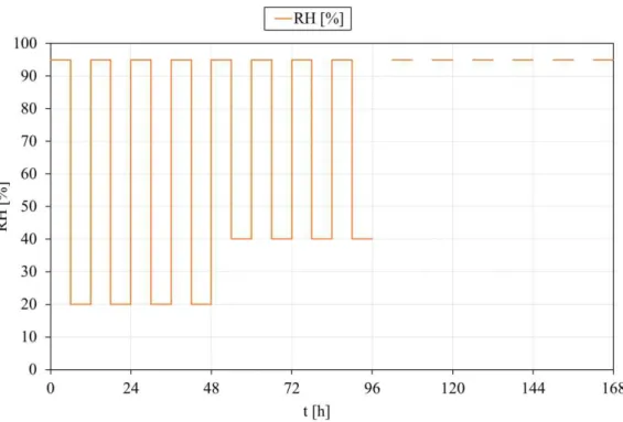
Figure 5: Z1 exposure Temperature and Humidity.
2.4.4 Exposure conditions for type Z2: Reactive coating system intended for
internal conditions
The test specimen shall be placed in a vertical position into the test chamber and exposed to the following cycle:
Table 5: Exposure cycles type Z2. Time
4 hours 16 hours 4 hours
23°C ± 3°C 80 % ± 5% RH
40°C ± 3°C 50 % ± 5% RH
5°C ± 3°C 50 % ± 5%RH
The cycle shall be repeated 21 times without interruption. After exposure the specimen shall be tested according to (section 2.3 ).
The chamber temperature change shall be at a rate of 1.5 K/min ± 0.5 K/min. During the period of temperature change, the change of humidity is not controlled, but condensation should be avoided. The duration of temperature change is included in the duration of the 16 h cycle.
Chapter 3:
Cone calorimeter experimental tests
3.1 Introduction
A cone calorimeter is a modern device used to study the fire behaviour of small samples of various materials in condensed phase. It is widely used in the field of Fire Safety Engineering. It gathers data regarding the ignition time, mass loss, combustion products, heat release rate and other parameters associated with its burning properties. Device usually allows the fuel sample to be exposed to different heat fluxes over its surface. The different models of the calorimeter can be used to evaluate different aspects of the flammable materials. The research using the cone calorimeters can be used for product safety, environment, and health services.
Intumescent coating is a reactive chemical material, which is used as the main fire protection material to steel structures. However, exposure to long-term environmental conditions can cause the intumescent coating to lose some of the reactive materials, thus reducing the effectiveness of the intumescent coating over time. Because fire safety requirement is throughout the entire life of a building structure, which may last many tens of years, it is important to understand the long-term protection performance of intumescent coating under exposure to environmental conditions, [7].
3.2 Preparation of the specimens
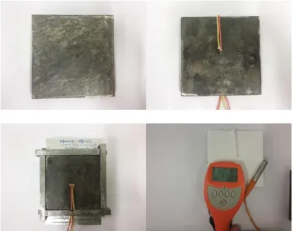
A total of 14 specimens were tested. The steel plate are cleaned before coated using angle grinder machine than two thermocouples type K are welded in the top and bottom to the plate to measure the temperature variation during the tests. The coating was applied using small frame to ensure approximately the dry film thickness, 8 plates were coated with 1 [mm] and the other with 0.5 [mm] on one side. After that, using Elcometer gauge, the average value of the dry film thickness was measured, see Figure 7.
Figure 7: Steel plate before and after coating.
After coating, the specimens should then be stored in an atmosphere during one week before fire testing.
3.3 Experimental setup
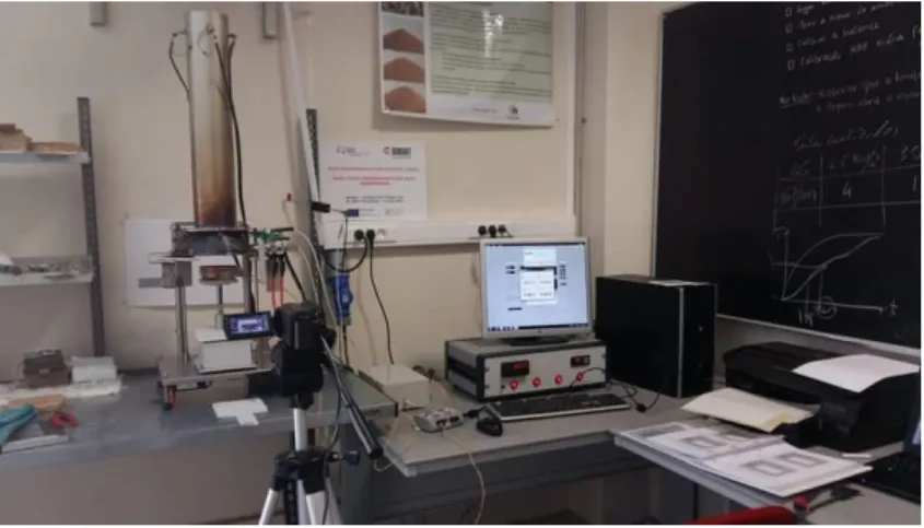
Figure 8: Cone calorimeter and experimental setup.
Before testing a sample or conducting a heat release rate calibration the cone heater temperature must be set to give the required heat flux. A heat flux meter is placed under the cone heater at the point corresponding to the centre of the specimen surface and the temperature controller adjusted until the required test flux is achieved, see Figure 9.
Figure 9: Sketch of the component of cone calorimeter.
standard ISO5660, [5], with two different heat flux 35 [kw/m2] and 75 [kw/m2] related to a temperature of 698 and 913 [°C] respectively. Temperatures are measured by means of two thermocouples type k, welded to the plate on the heating side and on the opposite side and related with a data acquisition to measure them during the test.
The dry thickness was also measured in 10 different points, the avrage value are presented. The distance between the sample surface and the heater remained unchanged, at approximately 40 [mm]. This means that with the increasing intumescence the top of the sample came closer to the cone surface. Due to the large volume of results, only a set of samples will be referenced in this experimental.
Table 6: Set of experimental testes. Reference: Heat flux/Steel Thick/Dry Thick/ Test N°.
specimens Heat flux
[kw/m2] ds [mm]
Nominal
DFT [µm] 𝑿̅𝑫𝑭𝑻 [µm]
Initial Mass [g] P1 75
14 500
483 1161.39
P2 75 606 1120.28
P3 35 628 1140.6
P4 75
14 1000
831 1155.73
P5 75 833 1127.6
P6 35 1107 1122.2
P7 75
5 500
751 407.9
P8 75 705 414.9
P9 35 589 449.6
P10 75
5 1000
1171 431.1
P11 75 1298 436.1
P12 35 886 512.8
P13 75
8 1000 943 639.7
P14 35 602 650.2
A1 75 14 -- -- 1145.1
35
A2 75 8 -- -- 636.7
35
A3 75 5 -- -- 492.3
3.4 Experimental tests results without aging:
3.4.1 Steel temperature evolution
The results of the tests made in the cone calorimeter are shown in Figure 10. The temperature evolution in steel plates without protection was also tested to attain the efficiency of this fire protection.
The temperature variation of differente samples is shown in Figure 11 and Figure 12, for different plates with steel thickness equal to 5, 8 and 14 [mm], submitted to heat fluxes of 35 and 75 [kW/m2]. The tested plates reach a steady temperature of 339 [°C] in test P14 and 479 [°C] in test P1 for 35 and 75 [kW/m2], respectively.
Table 7 present steel substracte temperature that may be achieved by the different specimens at time 15, 30, 45 and 60 [min] and the maximum thickness of the intumescent char.
Figure 10: Coated steel plates, with fixed thermocouples. Tested samples at 35 [kW/m2] and at 75 [kW/m2].
Figure 11, for a radiant heat flux of 75 [KW/m2], it could be seen that the specimen P1 has the maximum temperature with a dry film thickness of 483 [µm], while the minimum is for the test P11 with a maximum DFT about 1298 [µm]. At 35 [KW/m2] the highest and lowest temperature are shown in P14 and P6 respectively with dry film thickness of 602 and 1107[µm], as verified in Figure 12.
Compared to the specimens without protection, the steel temperatures of plates protected with intumescent coating decreases about 40% compared with the plates without protection.
Figure 11: Measured temperature in the steel plates for a radiant heat flux of 75 [KW/m2]. a) ds= 14 [mm], b) constant nominal DFT= 1 [mm].
a)
Figure 12: Measured temperature in the steel plate for a radiant heat flux of 35 [KW/m2]. a) ds= 5 [mm], b) constant nominal DFT= 1 [mm].
Table 7 presents the steel substrate temperature at time of 15, 30, 45 and 60 [min] and the final intumescent char thickness of all specimens. Through the table it is evident to see that the thickness of intumescent coating has good influence on keeping the steel at low temperatures.
a)
Table 7: Steel substrate temperature at different times.
specimens Heat flux
[kw/m2] ds [mm]
DFT [µm]
T [°C] Max thick [mm] 15 [min.] 30 [min.] 45 [min.] 60 [min.]
P1 75
14
483 316.15 404.54 453.47 479.04 10.28
P2 75 606 295.16 370.63 416.49 443.54 15.18
P3 35 628 245.22 278.56 294.73 306.74 14.82
P4 75
14
831 294.72 357.66 391.39 413.56 17.76
P5 75 833 276.13 341.52 380.67 405.83 19.72
P6 35 1107 230.05 267.33 280.84 292.13 14.77
P7 75
5
751 355.52 434.54 462.55 474.61 1)
P8 75 705 366.36 436.15 462.2 474.05 21.09
P9 35 589 286.67 310.33 325.67 334.05 14.85
P10 75
5
1171 299.08 362.45 381.54 390.78 28.22
P11 75 1298 283.41 344.44 366.58 376.58 26.31*
P12 35 886 273.02 292.96 307.59 315.05 18.09
P13 75
8 943 311.57 383.85 415.73 432.35 20.92
P14 35 602 279.78 309.86 327.52 338.67 14.93
1): There is no video so it is not possible to measure the intumescent development. *: The final intumescent char thickness is about 40 [mm].
3.4.1 Heat release rate (HRR)
Figure 13: Heat release rate of the intumescent at 75 [KW/m2].
Figure 14: Heat release rate of the intumescent at 35 [KW/m2].
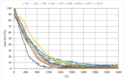
3.4.2 Mass loss
carbonaceous material. The mass loss rate is much more pronounced when the heating rate of the protective material increase, arising at higher heat fluxes and thicknesses of the lower steel sheet.
From Figure 15 it could be seen that the specimen P8 loses 50% of their mass in time of 294 second, while P7 at 448 [s], and this is due to the variation in the dry film thickness of the intumescent coating where the specimens P7 has a DFT of 751 while P8 has 705 [µm], so it could be said that the thickness of the intumescent coating has an influence on the mass loss because the thin DFT transforms quickly.
Figure 16 shows that the thickness of the steel plate has an impact on the mass loss because the thin steel plate heats faster and this can be seen in test P3 and P12 although the first has less DFT than the second.
Figure 16: Measured mass loss with time at 35 [KW/m2].
3.4.3 Intumescence development
Using discrete frames obtained from a digital camera during the tests, and by image processing techniques using Matlab, the intumescence development was measured over time. Figure 17 and Figure 18 presents the intumescent expansion of the coating for different thicknesses and radiant heat fluxes.
Higher intumescence may be observed in the samples P10 at 75 [kW/m2] and P12 at [35 kW/m2] with a maximum thickness of 28.22 [mm] and 18.09 [mm] respectively.
The figures show that the intumescence thickness is proportional with the dry film thickness (DFT) and inversely proportional with the steel thickness, depending also of the heat flux. The coating expantion increases with increasing thickness of the paint (DFT) and by decreasing the thickness of the steel plate, as can be seen whith comparison of P6 and P12.
Figure 17: Intumescence expansion for a radiant heat flux of 75 [KW/m2].
Figure 18: Intumescence expansion for a radiant heat flux of 35 [KW/m2].
The expansion measurement of the specimen P11 stopped at time of 512 second because the intumescence char go inside the cone calorimeter, making it impossible to continue measuring the expansion. Also, in case of the test P13 the camera moved at time of 665 [s] so it was not possible to present the results after this time.
Figure 20: Intumescence expansion with time of test P6 at 35 [kW/m2].
Figure 19 and Figure 20 shows the intumescence development with time, incompleted minutes for specimen P5 and P6 for a radiant heat flux of 75 and 35 [KW/m2] respectively. From the figures it could be seen that the intumescent coting of P5 don’t expand more after time equal to 19 [min], while for P6 it continues to expand until the time of 27 [min].
3.5 Experimental tests with aging
3.5.1 Accelerated aging process
The accelerated aging test was performed according to the European guideline N° 018, [3]. In this guidance, four types of environmental exposure are simulated: (a) type X for all conditions; (b) type Y for internal and semi-exposed conditions; (c) type Z1 for internal conditions which have above zero temperatures and high humidity; and (d) type Z2 for internal conditions that have above zero temperatures but humidity conditions that are not in class Z1. The accelerated aging test reported in this work adopted exposure condition Z1.
For exposure condition type Z1, each cycle of exposure is as follows: 8 h at (40±3) °C and (98±2) %RH;
16 h at (23±3) °C and (75±2) %RH.
To do the accelerating aging test, a QUV Accelerated Weathering Tester were used. This equipment reproduces the damage caused by sunlight, rain and dew. In a few days or weeks. The QUV tester can reproduce the damage that occurs over months or years outdoors. To simulate outdoor weathering, the QUV tester exposes materials to alternating cycles of UV light and moisture at controlled elevated temperatures. It simulates the effects of sunlight using special fluorescent UV lamps. It simulates dew and rain with condensing humidity and/or water spray.
In this work it couldn’t follow exactly the condition type Z1 according to the ETA Guideline because the temperature inside the QUV can not decrease more than 30 [°C] so the cycle was changed as follow: 8 hours at 40 [°C] and 16 hours at 30 [°C] with condensing humidity in all cycles.
According to ETAG018, 21 cycles of accelerated aging is equivalent to 10 years in service. Based on this correlation, 0 cycle, 4 cycles, 11 cycles and 42 cycles correspond to fresh coating, 2 years, 5 years and 20 years in service.
Table 8: Set of experimental testes with aging. Reference: Heat flux/Steel Thick/Dry Thick/ Test N°.
specimens Heat flux
[kw/m2] ds [mm]
Nominal DFT [µm] X DFT [µm] X DFT after aging [µm] Initial Mass [g]
S1 75 625 647 1149.3
S2 75 14 500 599 529 1134
S3 35 436 362 1155.3
S4 75 1359 * 1075.3
S5 75 14 1000 733 708 1166.8
S6 35 625 579 1158.7
S7 75 795 778 423.9
S8 75 5 500 712 696 407.2
S9 35 689 694 398.57
S10 75 1580 1990 429
S11 75 5 1000 1312 1530 419.6
S12 35 951 904 425.2
S13 75
8 1000 947 994 650.4
S14 35 752 695 648.8
*The protection was damage after the hydrothermal aging.
After the accelerated aging test a qualitative analyse of the intumescent protection was done, for the coating surface appearance, and the dry film thickness was measured before the cone calorimeter test. Figure 22 and Figure 23 show the state of the specimens after having gone 21 cycles of accelerated aging.
Figure 22: Intumescent coating surface after hydrothermal aging test of two different dry film thicknesses.
3.5.2 Cone calorimeter tests
3.5.2.1 Steel temperature evolution
After the specimens were subjected to an accelerated hydrothermal aging as described in the previous section, they were placed in a cone calorimeter. The tested plates reach a steady temperature of 560 [°C] in test S9 and 691 [°C] in test S8 for 35 to 75 [kW/m2], respectively.
The result obtained after the fire test are shown in Figure 24 and the measured temperature are presented in Figure 25 and Figure 26.
Figure 24: Coated steel plates after accelerated aging, with fixed thermocouples. Tested samples at 35 [kW/m2] and at [75 kW/m2].
The temperature decreases with increasing thickness of the coating (DFT) and by increasing the thickness of the steel plate. From Figure 25 it could be seen that the temperature evolution of the specimen S13 is higher than S10 although the first is thicker than the second, and this is due to the real DFT while S10 and S13 have a dry film thickness of 1580 and 947 [µm], respectively.
Figure 26 shows that the highest and lowest temperature can be observed in S12 and S6, respectively, with steel thickness of 5 and 14 [mm].
Figure 25: Measured temperature in the steel plate for a radiant heat flux of 75 [kW/m2] after hydrothermal aging test. a) ds= 14 [mm], b) constant nominal DFT= 1
[mm]. a)
Figure 26: Measured temperature in the steel plate for a radiant heat flux of 35 [kW/m2] after hydrothermal aging test. a) ds= 14 [mm], b) constant nominal DFT= 1
[mm].
3.5.2.2 Heat release rate (HRR)
The next figures show that the heat release rate is proportional with the dry film thickness and the heat flux. From Figure 27 the specimens S5 registered a heat release rate peak value of 17.60 [kW/m2] for time equal to 2509 [s] with a DFT of 733 [µm]. Figure 28 shown that the specimen S3 has the highest heat release rate with a peak value of 21.57 [kW/m2] at time 3495 [s].
a)
Figure 27: Heat release rate variation of the intumescent coating at 75 [kW/m2].
Figure 28: Heat release rate variation of the intumescent coating at 35 [kW/m2].
3.5.2.3 Mass loss
From Figure 29 it could be seen that the specimen S2 spend 90% of their mass in time of 459 [s], while S5 spend 61% at that time, and this is due to the variation in the dry film thickness of the steel plate. Figure 30 shows that the thickness of the steel plate has an impact on the mass loss because the thin steel plate heats faster.
Figure 29: Measured mass loss with time after hydrothermal aging test at 75 [kW/m2].
3.5.2.4 Intumescence expansion development
After hydrothermal aging test and when the specimens are exposed to elevated temperatures, the intumescent coating does not react, so there is no expansion in all the tests except in the specimen S10 that has a dry film of 1580 [µm]. Even for this sample the final thickness of the intumescent char is very low, about 5 [mm], see Figure 31.
Chapter 4:
Conclusions and future work
4.1 Main conclusions
This work presented the results of a series of fire tests on intumescent coating protected steel plate conducted in a cone calorimeter to assess the intumescent coating behaviour when used in fire protection before and after have been exposed to 21 cycles of hydrothermal aging corresponding to 10 years in service according to exposure condition type Z1 in European guideline ETAG 018-part 2 “Reactive Coatings for fire protection of steel elements”. The results have been presented in terms of the steel temperature, the heat release rate and mass loss measurement and the intumescence development.
The experimental tests shows that the fire resistance time increases with increasing thickness of the coating (DFT) and by increasing the thickness of the steel plate.
Intumescent coating suffered considerable reduction in performance after hydrothermal aging test. For example the steel plate temperature of specimen S2 was increased by about 270 °C compared to the steel temperature of P2 with fresh intumescent coating at specific time of 30 [min].
Intumescence development depends on the initial dry film thickness and on the incident heat flux, but the hydrothermal aging environment damage the expansion ability of the intumescent coating.
There is strong link between the surface appearance and fire protection performance of an intumescent coating. Coating surface appearance may be explored when determining a replacement strategy in real applications.
4.2 Future lines of investigation
In order to understand better the effect of the hydrothermal aging environment on the intumescent coating performance, it is necessary to study the impact in real structural elements protected with intumescent coatings. Other thing, the influence of time of exposure in this work is very high 21 cycles (simulating 10 years in service), so to see the degradation in intumescent coating performance it’s better to expose the coating to different cycles simulating different years in service.
To follow the exposure condition type Z1 according to the European guideline [3], the use of a climate chamber is better than the QUV Accelerated Weathering Tester see Figure 32.
Figure 32: Climate chamber.
Figure 33: Measured thermal conductivity of intumescent char before and after aging using HotDisk.
References
[1]. Wang, L.L., Y.C. Wang, and G.Q. Li, Experimental study of hydrothermal aging effects on insulative properties of intumescent coating for steel elements. Fire Safety Journal, 2013. 55: p. 168-181.
[2]. Wang, Z., E. Han, and W. Ke, Effect of nanoparticles on the improvement in fire-resistant and anti-ageing properties of flame-retardant coating. Surface and Coatings Technology, 2006. 200(20–21): p. 5706-5716.
[3]. Approvals, E.O.f.T., European Technical Approval Guideline (ETAG N° 018) Part 2 “Reactive Coatings for fire protection of steel elements” November 2011.
[4]. Xie, H.L., et al., Effect and mechanism of N-alkoxy hindered amine on the flame retardancy, UV aging resistance and thermal degradation of intumescent flame retardant polypropylene. Polymer Degradation and Stability, 2015. 118: p. 167-177.
[5]. STANDARD, I., ISO 5660-1: Reaction to fire tests ‘’Heat release, smoke production and mass loss rate’’. Part 1: Heat release rate (cone calorimeter method). 2002. [6]. Dong, Y., G.J. Wang, and Q. Su, Influence of degree of polymerization of ammonium
polyphosphate on anti-aging property of waterborne fire resistive coatings. Surface & Coatings Technology, 2014. 246: p. 71-76.
[7]. Wang, L.L., et al., Thermal conductivity of intumescent coating char after accelerated aging. Fire and Materials, 2013. 37(6): p. 440-456.
[8]. Roberts, T.A., et al., Fire resistance of passive fire protection coatings after long-term weathering. Process Safety and Environmental Protection, 2010. 88(1): p. 1-19.
[9]. F. Sutter, A.F.-G., J. Wette, P. Heller, Comparison and evaluation of accelerated aging tests for reflectors. Energy Procedia, 2014.
[10]. Luís M.R. Mesquita, P.A.G.P., Mário A.P. Vaz and Tiago M.G. Pinto, Decomposition of intumescent coatings: comparison between numerical method and experimental results. Application of Structural Fire Design, 2009.
[11]. STANDARDIZATION, E.C.F., EN 1363-1 Fire resistance tests -Part 1: General requirements. 1999.
A1. Experimental results of the steel temperature of the specimens without aging
Figure 34: Measured temperature in the steel plates for all tests at 35 [KW/m2].
A2. Experimental results of the steel temperature of the specimens after aging
Figure 36: Measured temperature in the steel plates for all tests at a radiant heat flux of 35 [KW/m2].
![Figure 2: X1 exposure UV lamp and water spray according to EN ISO 4892-3:2006, [12].](https://thumb-eu.123doks.com/thumbv2/123dok_br/16981099.762913/31.892.198.766.627.1005/figure-exposure-uv-lamp-water-spray-according-iso.webp)
![Table 7 present steel substracte temperature that may be achieved by the different specimens at time 15, 30, 45 and 60 [min] and the maximum thickness of the intumescent char](https://thumb-eu.123doks.com/thumbv2/123dok_br/16981099.762913/41.892.232.729.607.961/present-substracte-temperature-achieved-different-specimens-thickness-intumescent.webp)
![Figure 11: Measured temperature in the steel plates for a radiant heat flux of 75 [KW/m 2 ]](https://thumb-eu.123doks.com/thumbv2/123dok_br/16981099.762913/42.892.177.696.405.1077/figure-measured-temperature-steel-plates-radiant-heat-flux.webp)
![Figure 12: Measured temperature in the steel plate for a radiant heat flux of 35 [KW/m 2 ]](https://thumb-eu.123doks.com/thumbv2/123dok_br/16981099.762913/43.892.197.716.141.812/figure-measured-temperature-steel-plate-radiant-heat-flux.webp)
![Figure 13: Heat release rate of the intumescent at 75 [KW/m 2 ].](https://thumb-eu.123doks.com/thumbv2/123dok_br/16981099.762913/45.892.223.734.107.435/figure-heat-release-rate-intumescent-kw-m.webp)
![Figure 16: Measured mass loss with time at 35 [KW/m 2 ].](https://thumb-eu.123doks.com/thumbv2/123dok_br/16981099.762913/47.892.222.736.100.438/figure-measured-mass-loss-with-time-at-kw.webp)
