© European Geosciences Union 2003
and Earth
System Sciences
Numerical modelling of large landslides stability and runout
G. B. Crosta1, S. Imposimato2, and D. G. Roddeman3
1Universit`a degli Studi di Milano - Bicocca, Piazza della Scienza 4, 20126 Milano, Italy 2Politecnico di Milano, Piazza Leonardo da Vinci 32, 20133 Milano, Italy
3FEAT - Finite Element Application Technology, The Netherlands
Received: 24 September 2002 – Accepted: 4 December 2002
Abstract. Modelling of flow-like landslides is one of the possible approaches that can be used to simulate landslide instability and flow development. Models based on contin-uum mechanics and associated with a versatile rheological model are usually preferred to predict landslide runout and relevant parameters. A different approach has been used in this research. We have developed a 2-D/3-D finite el-ement code to analyse slope stability and to model runout of mass movements characterised by very large displace-ments. The idea was to be able to use different material laws already known, tested and verified for granular ma-terials. The implemented materials laws include classical elasto-plasticity, with a linear elastic part and different ap-plicable yield surfaces with associated and non-associated flow rules. The application of Finite Element methods to model landslide run-out, contrasts previous research where typically depth-averaged equivalent-fluid approaches were adopted. The code has been applied to the simulation of large rock avalanches and rapid dry flows in different materials and under different geological and geomorphological conditions.
1 Introduction
Large landslides usually present many different difficulties in performing slope stability and runout analysis. Large land-slides often assume a complex behaviour showing a con-tinuum passage from sliding to flowing. These phenom-ena have been described as complex and composite flows (Cruden and Varnes, 1996) and are characterized by an upper layer slightly deformed and a lower-basal layer with maxi-mum shear deformation. Furthermore, these landslides are frequently able to entrain or deposit material while mov-ing, allowing for important changes in mass and volume. A large variety of processes present these characteristics in na-ture, namely: rock and debris avalanches, debris flows, earth
Correspondence to:G. B. Crosta
flows, etc.. At the same time they can involve different types of material: rock, soil, a mixture of the two, water and ice, in different proportions, also in volcanic environments. Rock and debris avalanches are, for example, a major hazard in mountainous areas and are characterized by an extreme mo-bility and extremely high velocities. They have been cause of extensive damages and casualties through the centuries as reported in the literature both for non volcanic (Heim, 1932; Abele, 1974; Eisbacher and Clague, 1984; Evans et al., 1987; Evans and Clague, 1988; Evans et al., 1994; Erismann and Abele, 2001), volcanic (Voight et al., 1981; Siebert, 1984; Voight and Sousa, 1994; Sousa and Voight, 1995; Glicken, 1998) and marine environments (Moore et al., 1989) as well as in waste mining dump materials (Kent and Hungr, 1995).
The main consequence of the natural variability of these phenomena is the wide spectrum of observed mechanical be-haviours and the occurrence of long runout distances and large invasion areas. Then, the definition of the deriving haz-ard and the terrain zonation is quite complicate.
Slope processes characterised by a relevant and rapid runout require the determination of:
– the size or volume of the unstable mass and successively of the moving mass
– the triggering probability of the initial failure
– the geometry and size of the invasion area and of the deposit
– the intensity (velocity, energy, etc.) of the phenomenon along the path
– the probability to reach a specific point in space (reach-ing probability) and
– the time needed to reach any specific point along the track.
countermeasures and the level of consequent damages, the thickness of the deposit, the warning time available to evac-uate the exposed areas. Relationships between volume and mobility of rock avalanches have been presented and dis-cussed in the past (Heim, 1932; Scheidegger, 1973; Abele, 1974; Hsu, 1975; Davies, 1982; Legros, 2001) but they can-not give a complete description and understanding of the phe-nomenon.
In this paper we will prevalently play attention to rock and debris avalanches and to their modelling. Rock-avalanches are complex phenomena involving large volumes of preva-lently dry rock and/or debris. Their volumes range from about 105 to 1011m3 in subaerial settings but volumes up to 1013m3have been reported for extra-terrestrial landslides. They present different types of initial movement and mecha-nism (fall, slide, etc.) followed by a flow like movement of a disintegrating rock mass or debris and an abnormal mobility. While flowing the debris is able to run around major obsta-cles and to runup obstaobsta-cles up to some hundreds metres in relief.
The major problem with the comprehension and modelling of these phenomena consists in the completeness of their de-scription. Pre-, sin- and post-failure observations and data are fundamental constraints to develop, run, calibrate and validate a model of such events. This difficulty is clearly rep-resented by the large amount of theories and models that have been suggested in the literature (e.g. Heim, 1932; Shreve, 1968; Habib, 1975; Hsu, 1975; Melosh, 1979; Hutter and Savage, 1988; Sassa, 1988; Campbell, 1989; Kilburn and Soresen, 1998; Erismann, 1986; Erismann and Abele, 2001). To explain the exceptional rock avalanche mobility some researchers invoked the presence of a fluidising medium such as air, water, vapour, volcanic gases or a suspension of fine particles, or the presence of a water saturated basal layer. Other researchers explained this abnormal mobility by adopt-ing granular material models in absence of any fluid, both taking into account deposition or entrainment.
In the following we will propose a new continuum mod-elling approach to describe the transient movement of flow-like landslides, testing its performances on two case stud-ies. The finite element model is presented in its present two-dimensional version being the three-two-dimensional one under development.
2 Mechanical and mathematical modelling
Considerable work has been done in rock-avalanche or flow-like landslide dynamics especially to develop theoretical models for the description of motion. Both empirical (Heim, 1932; Scheidegger, 1973; Abele, 1974; Hsu, 1975; Davies, 1982; Legros, 2001) and numerical models have been pre-sented in the literature (Hutter and Savage, 1988; Sassa, 1988; Hungr, 1995; Campbell, 1989; Iverson and Denlinger, 2001; Denlinger and Iverson, 2001; Rochet Bouzid, 2001). Empirical relationships include those among different pa-rameters, namely: volume, area, runout distance, fall height,
apparent coefficient of friction for rock avalanches in differ-ent environmdiffer-ents (volcanic, non volcanic, with and without glaciers), and the control exerted by topography. Empirical models make use of available data sets on the different pro-cesses and therefore are subjected to a high degree of approx-imation. In fact, it is often difficult to have a complete and satisfactory description of: the actual occurred process, the initial volume and its exact detachment position and geome-try, the conditions of the slope where movement took place and where deposition occurred, the total duration, etc. As a consequence of this uncertainty and variability the results of the statistical analysis can be quite weak and a reliable rela-tionship can be difficult to be found.
Numerical models seem able of simulating some aspects of the flow behaviour of flow-like landslides and, ulti-mately, can be used to predict runout and to perform haz-ard zonation. Methods include sliding friction and velocity-dependent resistance models for point mass motion (Ko-erner, 1976, 1977; Pariseau and Voight, 1979), point mass velocity-dependent resistance models coupled to digital el-evation models (McEwen and Malin, 1989), sliding block models that include friction (Heim, 1932; Crosta, 1991; Erismann and Abele, 2001) and pore-water pressure pa-rameters (Hutchinson, 1986; Sassa, 1988), modified flood prediction models (Jeyapalan et al., 1983; Fread, 1988; Sassa, 1988; O’Brien, 1993), two dimensional and pseudo three-dimensional (Chen and Lee, 2000) depth-averaged La-grangian frictional models (Hutter and Savage, 1988) or us-ing a wider range of rheological models for the basal highly sheared layer (Hungr, 1995, Amar`u and Crosta, 2000), using a discrete element approach (Calvetti et al., 2000), and as-suming Coulomb-like behaviour coupled with highly refined mathematical solutions to reach a three-dimensional flow de-scription (Iverson and Denlinger, 2001; Denlinger and Iver-son, 2001). These models are capable of simulating both runout and velocity distribution along the path under a broad spectrum of capabilities, limitations, and degrees of sophis-tication. All these methods depend on the suitable choice of model parameters, requiring proper calibration. This calibra-tion is difficult to be definitive when only geometrical infor-mation (e.g. thickness, maximum or leading-edge runout dis-tance, trim-line tilting derived velocities) is available about the process itself and boundary conditions are complex or not completely known (effect of basal and lateral containment, free surface drag, basal scouring and entrainment and/or de-position of material during the motion, water absorption and material mixing during the flow, conditions of the material along the flow-path, etc.). On the basis of a given observed runout a unique solution cannot be obtained. In fact, a given runout can be achieved by an infinite number of values for the mechanical parameters and their combinations increase with the number of parameters used by the model. The ad-ditional constraints on model parameters can be provided by other field data such as flow duration, velocity estimates or measurements, or debris distribution.
con-ditions that prevailed during slope collapse, the evidences deduced from the debris deposit, the net effect of rock and debris interactions, both within the moving mass and with respect to the slope morphology, the role of interstitial flu-ids and heterogeneous pore fluid pressure conditions and of boundary conditions.
3 Finite element numerical analysis of runout
Continuum models invoke the classical conservation equa-tions of mass, momentum and energy. They have been fre-quently applied through a depth-averaged approach, where properties remain constant through material columns and no exchange or internal flow of the material is allowed. In general, the adoption of a continuum approach presents the advantage of representing the complex geometry of the avalanche (i.e. flow height, deposit size and geometry, runout length, velocity distribution).
In this section we present and discuss the Tochnog Profes-sional Finite Element code (Roddeman, 2001) and approach that has been used for the modelling of flow-like landslides (e.g. rock and debris avalanches) in this study (Crosta et al., 2002). More information about this code can be found at http://www.feat.nl.
3.1 Discretisation in space and time
Sliding and flowing rock and soil masses show very large displacements and deformations. If a traditional Lagrangian Finite Element would be used for modelization, also the fi-nite element mesh would be subjected to these large displace-ments and deformations. This would lead quite rapidly to a highly distorted mesh and, as a consequence, the calculated results become inaccurate. For this reason we decided to use a particular type of combined Eulerian-Lagrangian method. For such method, material displacements do not distort the FE mesh, such that accurate calculation results can be re-tained.
The discretization in space is done through isoparametric finite elements. Several types of elements can be used in the Tochnog FE code. For the present calculations we used triangular three-node elements in 2-D, and hexahedral eight-node elements in 3-D.
For discretization in time, Euler backward time stepping is applied, because of its high numerical stability. On top of this Euler scheme, we apply automatic time stepping and control of the number of equilibrium equations, such that a guaranteed bound is obtained of the unbalance error at the end of each time step. Since we disconnect material displace-ments from the finite element mesh, state variables need to be transported through the mesh. This is done by a Streamline Upwind Petrov Galerkin method (SUPG).
3.2 Material law
For the present research we applied classical elasto-plasticity to model the non linear path-dependent behaviour of soils.
This is the most complete and widely accepted approach to model both rock and soil-like materials and is supported by the results of different investigators (Hutter and Savage, 1988; Iverson and Denlinger, 2001).
The parameters adopted for the linear elastic part are the traditional Young modulus and Poisson ratio. As yield rule, the Mohr-Coulomb, Drucker-Prager and von Mises surfaces have been used and can be coupled. Their characteristic pa-rameters are, namely: friction angle, cohesion, dilatancy an-gle. Since we cope with granular materials, a non-associated flow rule has been applied.
The values of the material properties can be evaluated and attributed in different ways, namely: by a simple trial and er-ror calibration procedure, or by selecting representative val-ues according to the type of involved rock and/or soil. This second approach is clearly the most general one because does not require an antecedent event for calibration to have already occurred.
Different constitutive laws are available or under imple-mentation within the code. They include, namely: plastic and hypoplastic laws, hardening anisotropic laws and soften-ing laws.
3.3 Large deformation material description
As mentioned before, the displacements and strains in slides of rock and soil masses can be very large, especially for flow-like movements. Besides the above mentioned discretization issues, this also influences the material law that should be used. This should be such that any rigid body rotation should only lead to stress rotation, but not to additional stresses within the flowing mass. The problem, however, consists in the fact that the rigid body rotation component is not uniquely defined as part of an arbitrary deformation pattern. Numerous definitions are possible. For sliding and flowing masses, as in the case of large rock and debris avalanches, an updated Lagrange model is the more suitable. We applied an incrementally objective Lagrangian model, based on a polar decomposition of the incremental deformation tensor. 3.4 Start of calculation
To start the numerical calculations, we must reach the initial equilibrium stress state. This section of the computation is performed through static time stepping. During quasi-static time stepping, all inertial effects were left out. The assumption is that this part of the computation models the very long time nature did take to establish the initial gravity state.
3.5 Actual landslide calculation
Fig. 1.Location map of the 1987 Val Pola rock avalanche and the Ruinon rock-slide in Upper Valtellina, northern Italy. Position of swiss and italian seismic stations in the sketched area is represented.
The initial movement or occurrence of the landslide can be triggered by either lowering cohesion in time (for example, to simulate heavy rainfall effects or progressive weathering), or imposition of a base acceleration diagram (to simulate seis-mic triggering). After the landslide is triggered and the mass starts moving, time steps are taken till solution at rest is ob-tained.
Several post-processing options have been made available in the code and help in the visualization of the results. The material flow, the velocity pattern in time, and other vari-ables, can be shown as avi-true-color movies and mpeg files. Pictures of the initial state, intermediate and ultimate at rest state can be obtained in different digital formats.
4 Rock- and debris avalanche simulations
In this paper we will present only two two-dimensional sim-ulations of large rock- and debris-avalanches: the 1987 Val Pola rock avalanche and the hazardous Ruinon rockslide, both from the upper Valtellina area (Lombardy, northern Italy, Fig. 1). These two phenomena have been chosen be-cause of their characteristics, the suitable level of knowledge, their relative similarity and the high level of deriving hazard and risk (still existing for the Ruinon rockslide).
More examples and simulations have been already pre-sented and analysed in other papers (Crosta et al., 2002). These include a set of models with simple geometry but with multiple complex boundary conditions (entrainment and de-position of material, weak layers, softening behaviour, pres-ence of fixed and deformable obstacles, prespres-ence of water, etc.).
4.1 The 1987 Val Pola landslide
The Val Pola landslide was the most destructive and expen-sive landslide occurred recently in Italy. The 28 July Val Pola landslide (Lombardy, northern Italy, see Fig. 1) claimed
Fig. 2. Cumulative rainfall for the Upper Valtellina area:(a)daily cumulative rainfall for the June–July 1987 period. The cumulative values for the most rainy year, between 1988 and 2001, are reported for the Arnoga and the Cam Boer (Val Pola crown area) rain gauges. Occurrence of the Val Pola rock avalanche is represented by the grey arrow;(b)hourly cumulative rainfall for the 1987 event.
27 lives and a total cost of about 400 million euros including destruction of villages, road closure, monitoring and warning systems, construction of permanent outlet tunnels and earth movements (Govi, 1989; Costa, 1991; Crosta, 1991; Azzoni et al., 1992).
Between June and July 1987, Valtellina was hit by an ex-ceptional meteorologic event. About four times the aver-age rainfall for the area felt between the 15 and 22 of July (Fig. 2), while the 0◦C isotherm remained between 3500 and 4000 m a.s.l. causing rapid glacier melting. At that time, the Val Pola creek deeply eroded its valley flanks undercut-ting the northern limit of an old landslide accumulation. The eroded material caused debris flows which created a large al-luvial fan damming the main Adda River valley and caus-ing formation of a shallow lake. The old landslide mass was formed by highly fractured and tectonized diorite, gab-bro, ortho-quartzite, amphibolite and fine-grained gneiss and it was suspended along the right hand flank of the valley (Fig. 3, Crosta, 1991).
Fig. 3. The old Val Pola landslide accumulation and main scarp before the occurrence of the 1987 rock avalanche. The asymmetric size and geometry of the main scarp can be recognised together with the debris fan at the toe of the slope. The same features can be recognized in the 1:10 000 scale 1984 topographic map. North is to the right.
Fig. 4. Main geometric features of the Val Pola rock avalanche along a downslope profile.
Val Pola rock-avalanche to strongly constrain the successive modelling phases. The old landslide accumulation was char-acterized by a large and continuous scarp up to 700 m in length and 100 m in relief and a densely vegetated fan-shaped accumulation was visible 500 m below the landslide toe.
On 25 July, a 600 m long fracture was observed at the base of the old main scarp. Fracture length increased up to 900 m. On 28 July at 07:23 AM, a volume between 34 and 43 millions of cubic meters (according to different estimates) detached from the slope. It moved rapidly down the west-ern valley flank to reach the valley bottom, raised for 300 m on the opposite valley flank and flowed both upstream and downstream (Fig. 4) along the valley. After the failure the compound geometry of the source area, due to the presence of major fault and schistosity planes, was observed (Crosta, 1991).
Fig. 5. The Val Pola rock-avalanche deposit is sketched showing the main geometrical and geomorphological features with a rough subdivision in source, transportation and deposition areas. The ac-cumulation is subdivided according to prevalent grain size as ob-served at the surface. Secondary slides, connected to the rapid de-scent after the runup of the material on the opposite valley flank, are represented.
The landslide entrained 5 to 8 millions cubic meters of de-bris along the track. The rock avalanche dede-bris is thought to have bulked by about 30% during deposition. The stream run of the mass stopped at 1.5 km from the down-slope axis followed by the landslide (Fig. 5). The upstream movement was characterized by a large mud wave, up to 35 m high, that reached a distance of 2.7 km whereas the maximum distance reached by the debris was about 1 km. The rock avalanche is characterized by an H/L ratio of 0.51 according to the centre of mass motion along the direction of motion and without considering up- or down-stream runout. Downstream and upstream maximum runout distances give values of 0.35 and 0.3, respectively.
Fig. 6.Cross section of the Ruinon rockslide as resulting from field surveys and borehole data.
Bulk weights between 19.8 and 21.6 kN/m3 and specific weight ranging between 27.5 and 28.8 kN/m3 were deter-mined and large triaxial tests resulted in angles of internal friction ranging between 45◦and 47◦with no cohesion.
The energy released by the landslide during its motion has been recorded by seismograph stations (Fig. 1) both in Italy (8 stations) and Switzerland (7 stations) (De Simoni et al., 1988). The total duration of the seismic records ranges be-tween 70 s and 120 s. Analyses of the seismographs show a sequence of 3 to 4 strong impulses (roughly at 17 s, 26 s, 35 s, 60 s and 75 s) distributed along a 70 s time interval.
4.2 The “Ruinon” rockslide as a potential rock avalanche The “Ruinon” rockslide is located in Valfurva, a NW-SE trending glacial valley in the Upper Valtellina (Fig. 1). This rockslide is located few kilometres from the 1987 Val Pola rock-avalanche in an area characterised by a continental-alpine rainfall regime with rainy summer and autumn. An-nual average, maximum and minimum rainfall amount, re-spectively, at 750 mm, 1300 mm and 300 mm (1891–1990 data set). Phyllites, the most frequently involved lithotype in rock-sliding and deep-seated gravitational slope deforma-tions in Upper Valtellina, outcrop in the area. Four main joint sets strongly control the slope stability and the entire valley flank is affected by a large deep-seated slope deformation (Agliardi at al., 2001). Many different morpho-structures (e.g. scarps, counterscarps, trenches), cut both the bedrock and till and rock glacier deposits of Holocene age along the slope.
The Ruinon rock-slide has been known for decades (Crosta et al., 1999) and recurring instabilities (e.g. debris flow, rockfall, etc.) have been recorded in coincidence of exceptionally heavy rainfall (e.g. 1960, 1983, 1987, 1997). Since 1997 the movement is subjected to an accelerating phase. The rockslide geometry and kinematics have been studied by the analysis of a LIDAR-ALTM survey, the multi-temporal interpretation of aerial photos (1954, 1981, 1998)
Fig. 7. 2-D finite element mesh generated for the Val Pola rock avalanche model: space domain is represented by blue elements, landslide mass by red elements and the failure and topographic sur-face by black elements.
both combined with a detailed field survey and geomechan-ical analysis of surface and sub-surface data (5 boreholes; Fig. 6).
The rockslide is characterized by a compound movement (translational and rotational sliding) involving more than 20 Mm3of material. It extends between 1700 m and 2120 m a.s.l., but mapped scarps and trenches suggests a possible expansion of the movement up to 2200 m a.s.l. The rock-slide is suspended along the valley flank, as was the Val Pola rock avalanche, and it is suitable to originate a fast moving rock avalanche. Two active main scarps, called Upper tween 2100 m and 2120 m a.s.l., 600 m long) and Lower (be-tween 1890 m and 1930 m a.s.l.), respectively, characterise the slope.
foliation) have been performed. Remoulded cataclastic ma-terial has been tested in direct shear tests (internal friction angle ranging between 24.5◦and 26◦).
4.3 Model setup
The critical assumptions of the models are those of two di-mensional flow and constant physical mechanical proper-ties. These assumptions constrain the flow models. Lateral changes in slide mass geometry and channel shape are gen-erally not considered in the two dimensional analysis.
Mechanical parameters were assumed to be temporally and spatially constant. As a consequence these parameters reflect the average flow properties during its entire develop-ment. This assumption may be reasonable for short runout flows or flows where property changes may not be too severe. Then, results for long-runout landslides must be interpreted with particular caution.
The Val Pola rock avalanche and the Ruinon rockslide evo-lution were modelled along a track extending from the source area (observed or hypothesised) through the valley thalweg and up along the opposite valley flank (Figs. 4 and 5). The initial rockslides were modelled as single failure masses ly-ing directly on the post failure observed or most probable failure surface. Verification of the most probable expected failure surface has been performed through finite elements 2-D and 3-D slope stability analyses and limit equilibrium analyses (Crosta et al., 2002)
The values for the significant physical and mechanical pa-rameters in the two analyses are summarised in Table 1 both for the landslide mass and the failure-sliding surface. These values are the result both of field survey and laboratory tests and of model calibration.
For the here discussed models we decided to use an elasto-plastic model with a Drucker Prager yield criterion. This choice presents two advantages: the minimization of the number of constitutive parameters to calibrate, the reduction of numerical problems. Choosing this model we can directly use values for the parameters representative of the material properties and obtainable through laboratory testing. At the same time, the conical shape of the plastic surface allows to avoid numerical problems connected to the presence of edges on such a surface, as for the Mohr-Coulomb criterion, where the continuity of the derivative operator is lost.
5 Rock avalanche simulations and results
5.1 Val Pola rock avalanche
The above-described finite element method has been applied to run flow simulations for the Val Pola rock-avalanche and the Ruinon rockslide.
Starting from the set of data available for the pre- and post-failure conditions at the Val Pola rock avalanche site we have chosen a cross section along the valley to run the flow simulations. The FE mesh has been generated accord-ing to this set of information. A total of 7682 triangular
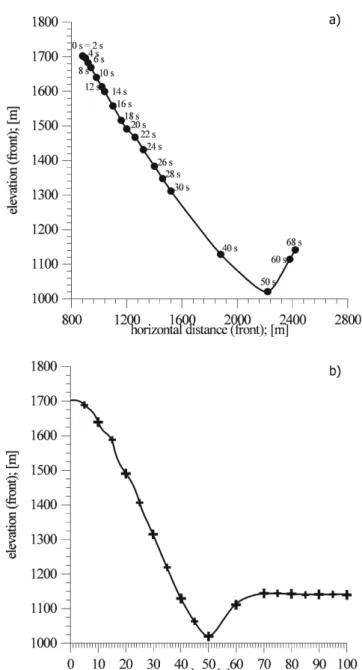
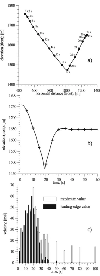
Fig. 8. Val Pola analysis: (a)Leading-edge position at different time steps along the slope profile;(b)elevation of the leading-edge vs. time showing its runup and arrest time.
finite elements have been generated (Fig. 7) for the three main domains, namely: the initial landslide mass geometry (443 elements), the failure surface and the topographic sur-face (329 elements), the space domain where transition of the moving mass is retained possible (6910 elements).
The initial state of stress within the landslide mass has been computed starting from the assumption that the plas-tic parameters, controlling the behaviour of the mass in the pre-failure state, are high enough to guarantee the formation of the in situ stress under elastic conditions.
Table 1.Values adopted for the physical mechanical properties of the landslide mass and the failure and sliding surface
Landslide mass properties
Case Bulk Elastic Poisson Constitutive Friction Cohesion Dilatancy
Study weightγ modulus E coefficientν model Angle8 c 9
(KN/m3) (KN/m2) (◦) (KN/m2) (◦)
Val Pola 20.6 100 000 0.23 Drucker 45 0.01 0
Prager
Ruinon 27.5 100 000 0.23 Drucker 28 400 0
Prager
Sliding surface Properties
Case Bulk Elastic Poisson Constitutive Friction Cohesion Dilatancy
Study weightγ modulus E coefficientν model Angle8 c 9
(KN/m3) (KN/m2) (◦) (KN/m2) (◦)
Val Pola 20.6 100 000 0.23 Drucker 18 0.004 0
Prager
Ruinon 27.5 100 000 0.23 Drucker 12 5 0
Prager
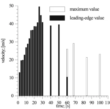
Fig. 9. Maximum recorded velocities in the Val Pola analysis: in black are the leading-edge velocities, in white are the maximum values within the landslide body and tail. Progressive decrease of leading edge velocity is recognizable.
These parameters enabled the model rock avalanche to run for a total duration time of 68 s, to deposit an accumulation with maximum thickness of about 100 m, and the leading-edge to reach the maximum elevation of 256 m above the antecedent valley thalweg, against the observed 300 m.
The kinematics of the simulated event is represented in Figs. 8a and b where the position of the model rock avalanche edge at different instants is plotted. Peak leading-edge velocities of approximately 50 m/s (Fig. 9) are obtained between 20 and 30 s after flow initiation. The avalanche ve-locity increase progressively during the initial 20 s to become constant between 30 s and 50 s, and decreasing progressively up to the moment when the leading-edge reach the valley thalweg. The position of the rock avalanche leading-edge is also described in Fig. 8. It also evidences the relative veloc-ity along the track and the arrest time. The maximum com-puted velocity within the flowing mass and the leading-edge velocity are reported in Fig. 9 with respect to time. During the initial part of the avalanche motion, the maximum veloc-ity coincides with that of the leading-edge. After the arrest of the leading-edge at 68 s, the maximum velocity is relative to points progressively close to the tail of the moving mass where movement persists.
Fig. 10.Val Pola rock avalanche model 10 s after movement onset:
(a)material profile,(b)velocity field,(c)velocity vectors.
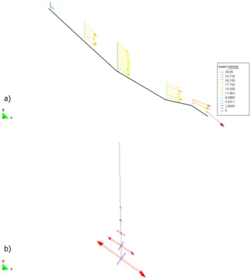
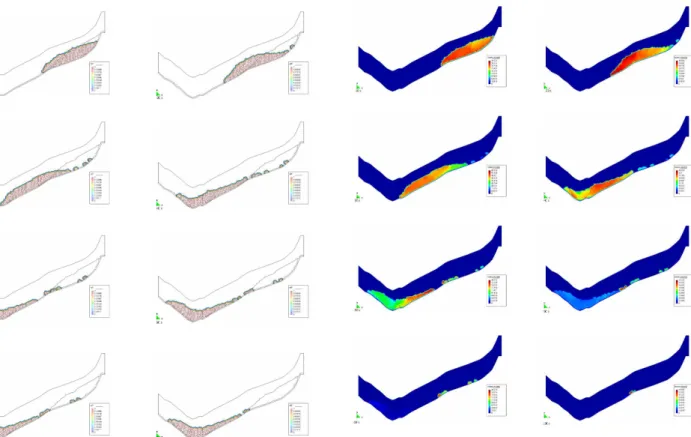
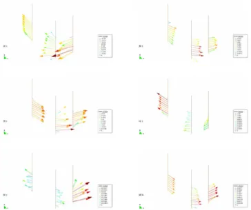
flowing mass without introduction of depth averaging or sim-ilar simplifying assumptions. Figures 10a, b and c show, re-spectively, after 10 s from the motion onset: the geometry and position of the mass, the velocity field and the velocity vectors. These figures already show the increase in velocity within the moving mass and at its front. Six different verti-cal profiles within the moving mass (Figs. 11a and b) have been chosen to examine the distribution of velocity and its direction during this initial stage of motion. The mass is still compact while moving parallel to the failure surface, with no relative motion of the different sectors. This is evidenced by plotting the plastic strains (Fig. 11b) along the central ver-tical profile (the third from the upper limit as in Fig. 11a).
a)
b)
Fig. 11. Val Pola rock avalanche model 10 s after movement initi-ation as in Fig. 10:(a)plot of the velocity vectors along 6 vertical profiles showing a rigid like movement(b)plastic strains along the central vertical profile showing localization at the rock slide base.
Their localisation close to the failure surface implies a rigid behaviour of the moving landslide mass.
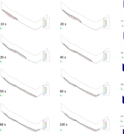
A sequence images of landslide material distribution and velocity field contours (Figs. 12 and 13), as obtained from the model at different time steps (10, 20, 30, 40, 50, 60, 68 and 100 s), illustrates the progressive thinning of the mass and the maximum velocity in the front area. During the ini-tial 20 s the zone of maximum velocity isolates, just down-slope of the toe of the failure surface, a well-defined sector resembling a “landslide” within the front. This pattern sug-gests the disaggregation that occur within the failing mass in correspondence of such a knee-point. Again during the ini-tial 40 s the mass elongate and increase in velocity up to the valley thalweg with maximum values at the front. A progres-sive decrease in the front velocity is observed with continu-ous movement at the flow tail also after 100 s. We must stress at this point that the simulation has been stopped after 100 s. Thus, the final position of the rock avalanche tail does not coincide with the one observed in the field.
One more figure (see Figs. 13b and c) shows the contours of the plastic invariant,k, linked to the tensor of the incre-ment of the plastic strainǫ˙plij. The plastic invariantkcan be written as:
·k= q
0.5ǫ˙plijǫ˙ijpl
10 s
30 s
50 s
68 s
20 s
40 s
60 s
100 s
Fig. 12. Sequence of images showing at successive time steps the geometry of the flowing mass. Maximum runup occurs at 68 s after movement onset, whereas the rear part of the mass is still moving after 100 s.
The same set of contour intervals have been chosen to make the plots comparable. At 68 sec we observe that the plas-tic strain is no more localised at the bottom of the landslide mass (i.e. along the topographic surface) but they are spread within the entire thickness of the flowing mass. This is par-ticularly interesting because it is in contrast with some of the assumptions usually advanced in depth averaged mod-els where strain localization at the basal surface is requested. Plastic strains continue up to the end of the simulation (100 s) especially in the upper part of the slope where material is still in motion. A sort of discontinuity in the plastic strain field is observed in proximity of the toe of the failure surface, at the junction with the topographic surface. Again, this pattern is coherent with the computed velocity and suggests the im-portant role of this sector in disaggregating the failing rock mass.
5.2 Ruinon rockslide
The Ruinon rockslide represents a case where numerical modelling has been used to evaluate hazard zonation for a possible rock avalanche evolution of the movement. The available data (Crosta et al., 1999) for the Ruinon landslide have been used: to trace a cross section along the slope and the opposite valley flank, to delineate and characterise the unstable mass.
Fig. 13.Sequence of images showing:(a)the velocity field within the flowing mass at successive time steps. Maximum velocities are in dark red, lower are in blue. The two lowest images: (b)and(c)
show the plastic invariant,k, linked to the tensor of the increment of the plastic strain
˙
ǫijpl
at 68 and 100 s, respectively.
Fig. 15. Ruinon rock slide model: (a)Leading-edge position at different time steps along the slope profile; (b) elevation of the leading-edge vs time showing its runup and arrest time,(c) max-imum recorded velocities: in black are the leading-edge velocities, in white are the maximum values within the landslide body and tail.
Fig. 16. Velocities computed for the Ruinon rock slide model at different time steps along a vertical profile placed at the valley thal-weg. Progressive decrease in velocity and thickening of the mass with increasing time are recognizable.
A FE mesh with a total of 5558 triangular finite elements has been generated (Fig. 14; 738 elements for the initial land-slide mass geometry, 327 for the failure surface and the to-pographic surface). The assumed values for the physical-mechanical properties are reported in Table 1. The initial state of stress has been established and the failure has been triggered with the same approach presented for the Val Pola rock avalanche.
Fig. 17. Ruinon rock slide model. Sequence of images showing at successive time steps the geometry of the flowing mass. Maximum runup occurs at about 30 s after movement onset, whereas the rear part of the mass is still moving after 100 s. Figures show separation and independent motion at the avalanche rear part.
flowing mass remains almost constant (about 10 m) with time but it must be stressed that this value can be controlled by the size of the FE mesh. The thickness of the entire mass in-creases progressively from about 40 m (after 20 s) to its final value of about 110 m.
The distribution of the mass at different time steps along the slope is represented in Fig. 17. The general shape of the profile can be observed, together with the progressive thin-ning of the mass, the detachment, movement and arrest of some material at the rear end of the mass along the failure plane and topographic surface.
The velocity field is represented in Fig. 18 at the same time steps as for Fig. 17. Again the maximum velocity starts at the leading-edge to gradually propagate within the mass with a sharp discontinuity at the toe of the failure surface. This change is similar to the one observed for the Val Pola rock avalanche but it is more marked.
To improve the understanding of the phenomenon we rep-resent the velocity vectors for the points along the topo-graphic surface and along 6 vertical profiles distributed along the slope (Fig. 19). The figure shows the relative distribu-tion of the velocities along the base and the slight changes in direction of the vectors along the vertical profiles. These
Fig. 18. Ruinon rock slide model. Sequence of images showing the velocity field within the flowing mass at successive time steps. Maximum velocities are in dark red, lower are in blue. A clear change in velocity value occur in the landslide sector which over-comes the toe of the failure surface implying the complete disag-gregation and disruption of the initial rock mass.
changes in direction become clearly more important in prox-imity of the valley thalweg when the mass is subjected to a strong change in direction and to important internal deforma-tions. This last point is also suggested by the plot of plastic strain along the topographic surface and the vertical profiles. Plastic strains are represented in vector format along the prin-cipal directions and prevalently show a shear component par-allel to the slope surface. Along the lowest vertical profiles plastic strain accumulates also within the mass with constant principal directions but with decreasing intensity toward the upper material surface.
Fig. 19.Ruinon rock slide model 24 s after movement initiation:(a)
velocity vectors along 6 vertical profiles and the sliding surface are represented,(b)plastic strains along the 6 vertical profiles and the sliding surface, as in Fig. (a). Strain localization prevails along the slope and internal strains become more relevant at the valley bottom and during runp.
6 Discussion and conclusions
Material involved in large flow-like landslides is often char-acterised by a wide range of grain sizes. The deposits include massive blocks as well as very fine particles (up to clay size) and this often precludes the performance of meaningful labo-ratory and field measurements. The mechanical behaviour of the finer fraction is not generally representative of the entire flow. Furthermore, deformation mechanisms and pore fluid pressure conditions typical of large scale flows are difficult to replicate in small scale testing. Numerical simulations can be used to partially overcome these difficulties and to assess and comprehend the flow behaviour of flow-like landslides. These models can also predict landslide runout and runup to perform an hazard zonation.
Numerical methods for flow-like landslide modelling de-pend heavily on different factors, namely: the type of mod-elling approach, the appropriate selection of constitutive models and model parameters, the understanding of the as-sumptions and limitations of the adopted modelling proce-dure, the suitability of the model to simulate or include both morphological and physical-mechanical constrains and boundary conditions. In addition, estimation of the geometry and volume of a potential slope failure is of critical impor-tance.
In this paper we present a new numerical modelling ap-proach based on a sophisticated finite element technique. We applied this approach both to back-analyse a large recent rock
Fig. 20.Ruinon rock slide model at different time steps. The three lower vertical profiles from Fig. 19 are shown. Oscillations of the velocities can be recognized.
Fig. 21.Ruinon rock slide model. Maximum velocities computed at one of the three vertical profiles of Fig. 20 are plotted versus time. Velocity vectors are plotted with positive sign to the left (runup) and negative to the right (descent after runup). Oscillation of the velocities within the avalanche mass are evident starting from 32 s.
avalanche (Val Pola) and to model the flow behaviour of a potential rock avalanche (Ruinon). We can add some more comments concerning the modelling results to the observa-tions already made in the paper.
thickness was about 90 m The difference can be easily im-puted to the position of the modelled landslides profile and to the three-dimensional effects connected to the up-stream and down-stream movement of the flowing mass. These two opposite flows took place probably both during the runup of the rock avalanche leading-edge and after its maximum reach and during the partial return flow down of the opposite valley flank. As a consequence, this is an example of how a com-plete calibration of two-dimensional models based on runout only is ambiguous and only the use of more constrains (total and partial arrival times, thickness of the deposit, maximum trimline height, etc.) can help in solving the problem.
Then, these values of the physical-mechanical parameters that allow the leading-edge to stop at the observed distance and elevation can only be considered as upper bounds val-ues. The adopted model parameters represent an average two dimensional rheology required for rock avalanche debris to match the runout and/or the run-up. Then, as suggested by Sousa and Voight (1995), the model might be regarded as less stiff than the prototype during early stages of movement when fragmentation and disaggregation of the rock mass were not complete and flow was transitional from frictional sliding. In any case we must suggest that for these types of phenomena the pre-failure rock mass is usually highly frac-tured and it is completely opened before or when it over-come the toe of the failure surface. Furthermore, a continu-ous fragmentation (i.e. fracturing and subdivision) continues all along the flow occurrence as suggested by field observa-tions and corroborated by our modelling results.
Then, an important model limitation is the assumption of constant mechanical properties throughout flow occurrence. For long-runout flows modelled with constant mechanical parameters and calibrated according to the total runout length it seems more correct to adopt values of the material proper-ties typical of the conditions existing during the intermediate to terminal stages of flow. This assumption can be at the ori-gin of high early stage velocities. To overcome this limita-tion, we are presently implementing the numerical model by introducing a softening behaviour for the landslide material and the surface on which movement takes place.
Most of the developed continuum models apply a depth-averaged approach. The most relevant difference in our study consists in the possibility to consider and analyse internal material strains. As presented in the flow simulation results, the depth-averaged assumption can be quite limiting espe-cially in presence of some morphologic features. These fea-tures include, namely: sharp changes in flow direction, knee points, obstacles of different nature and deformability, etc. Furthermore, it has been suggested that the absence of very fine basal layers and of pseudo-tachylytes (very fine or glass like material) indicates that energy dissipation during flow of large rock avalanches generally takes place also within the moving mass and not only at its base (Legros et al., 2000).
One more relevant point is the role of material entrainment and deposition during the flow. In case of the Val Pola rock avalanche scouring of the slope material along the track was relatively limited (mainly because of the limited thickness of
the slope debris cover) and we didn’t considered it in the sim-ulations. Nevertheless, it is known that entrainment for some rock avalanches and especially for relatively small flow like landslides might become relevant, implying an increase in volume of two to 3 orders of magnitude. Eventually, debris cover (talus, colluvial and alluvial deposits) could play a de-terminant role in increasing flow mobility by different mech-anisms (undrained loading, strain localization in softer mate-rial, weak wet sediment and river water entraiment, etc.). Acknowledgements. Enel Hydro spa kindly provided access to some data regarding the Val Pola rock avalanche. This work has been partly funded by the DAMOCLES Project, EVG1–1999– 00027. All Finite Element calculations results are courtesy of Finite Element Application Technology, FEAT.
References
Abele, G.: Bergst¨urze in den Alpen, Wissenschaftliche Alpenvere-inshefte 25, Muenchen, 1974.
Agliardi, F., Crosta, G., and Zanchi, A.: Structural constraints on deep seated slope deformation kinematics, Engineering Geology, 59, 83–102, 2001
Amar`u, M. and Crosta, G.: La modellazione numerica per la pre-visione delle distanze di massimo espandimento di frane a rap-ida evoluzione V◦Convegno Nazionale dei Giovani Ricercatori in Geologia Applicata. 8–11, ottobre 1996, Cagliari, ISBN 88– 900558–0–4, 1, 129–137, 2001
Azzoni, A., Chiesa, S., Frassoni, A., and Govi, M.: The Valpola Landslide, Eng. Geol., 33, 59–70, 1992.
Barton, N. R. and Choubey, V.: The shear strength of rock joints in theory and practice, Rock Mechanics, 10, 1–54, 1977.
Barton, N. R., Lien, R., and Lunde, J.: Engineering classification of rock masses for the design of tunnel support, Rock Mechanics, 6, 183–236, 1974.
Bieniawski, Z. T.: Engineering rock mass classification, Wiley, New York, 1989.
Calvetti, F., Crosta, G., and Tatarella, M.: Numerical simulation of dry granular flows: from the reproduction of small-scale exper-iments to the prediction of rock avalanches, Rivista Italiana di Geotecnica, Patron Editor, Bologna, 21, 2/2000, 21–38, 2000 Campbell, C. S.: Self-lubrication for long runout landslides, J.
Geol., 97, 6, 653–665, 1989.
Chen, H. and Lee, C. F.: Numerical simulation of debris flows, Canadian Geotechnical Journal 37, 146–160, 2000.
Costa, J. E.: Nature, mechanics, and mitigation of the Val Pola land-slide, Valtellina, Italy, 1987–1988. Zeitschrift f¨ur Geomorpholo-gie 35, 15–38, 1991.
Crosta, G.: Studio di movimenti in massa, Modellizzazione teor-ica e sperimentale con osservazioni e rilievi di campagna, PhD Thesis, Univ. Studi di Milano, 137, 1991.
Crosta, G., Agliardi, F., and Frattini, P.: Convenzione di studio sulla Frana del Ruinon (Valfurva, Sondrio), Technical report, Regione Lombardia – Dipartimento di Scienze Geologiche e Geotecnolo-gie, Universit`a degli Studi di Milano-Bicocca (in Italian), 1999. Crosta, G., Imposimato, S., and Roddeman, D.: Numerical
mod-elling of large landslide stability and runout, EGS 27th General Assembly, Geophysical Research Abstracts, European Geophys-ical Society, 4, 2002, EGS02–A–02241, 2002.
Workshop on Massive Rock Slope Failure; New models for Haz-ard assessment, Celano Italy, June 2002, Kluwer Special NATO Publ., in print, 2003.
Cruden, D. M. and Varnes, D. J.: Landslide types and processes, in: Landslides-investigations and mitigation, edited by Turner, A. K. and Schuster, R. L., Washington D.C., National Academy of Sciences, Transportation Research Board Special Report, 247, 36–75, 1996
Davies, T. R. H.: Spreading of rock avalanche debris by mechanical fluidization, Rock Mechanics, 15, 9–24, 1982.
Denlinger, R. and Iverson, R. M.: Flow of variably fluidized gran-ular masses across three-dimensional terrain: 2, Numerical pre-dictions and experimental tests Journal of Geophysical Research, 106, 553–566, 2001.
De Simoni, B., Migani, M., and Moia, F.: Analisi preliminare delle registrazioni della caduta della frana di Val Pola da al-cune stazioni sismiche italiane e straniere, MIR’88, Conferenze di Meccanica e Ingegneria delle rocce, Torino, 7, 1–5, 1988. Eisbacher, G. H. and Clague, J. J.: Destructive mass movements
in high mountains: hazard and management, Geol. Survey of Canada, Paper 84–16, 230, 1984.
Erisman, T. H.: Flowing, rolling, bouncing, sliding: Synopsis of basic mechanisms, Acta Mech., 64, 101–110, 1986.
Erismann, T. H. and Abele, G.: Dynamics of rockslides and rock-falls, Springer-Verlag, Berlin, 316, 2001.
Evans, S. G. and Clague, J. J.: Catastrophic rock avalanches in glacial environments, in: Proceedings of the 5th International Symposium on Landslides, edited by C. Bonnard, 10–15 July, Lausanne, Switzerland, A. A. Balkema, Rotterdam, The Nether-lands, 2, 1153–1158, 1988.
Evans, S. G., Aitken, J. D., Wetmiller, R. J., and Horner, R. B.: A rock avalanche triggered by the October 1985 North Nahanni earthquake, District of Mackenzie, NWT, Canadian Journal of Earth Sciences, 24: 176–184, 1987.
Evans, S. G., Hungr, O., and Enegren, E. G.: The Avalanche Lake rock avalanche, Mackenzie Mountains, Northwest Territories, Canada: dating, description, and dynamics, Canadian Geotech-nical Journal, 31: 749–768, 1994.
Fread, D. L.: The NWS DAMBRKmodel: theoretical back-ground and user documentation, National Weather Service, Sil-ver Spring, Md, Hydrologic Research Laboratory, HRL–256, 315, 1988.
Glicken, H. X.: Rockslidedebris avalanche of May 18, 1980, Mount St. Helens volcano, Washington, Bulletin of the Geological So-ciety of Japan, 49, 55–105, 1998.
Govi, M.: The 1987 landslide on Mount Zandila in the Valtellina, Northern Italy, Landslide News 3, 1–3, 1989.
Habib, P.: Production of gaseous pore pressure during rock slides, Rock Mechanics, 7, 193–197, 1975.
Heim, A.: Bergsturz und Menschenleben, Z¨urich, 218 p, 1932. Hoek, E. and Brown, E. T.: Underground excavations in rock,
Insti-tution of Mining and Metallurgy, London, 1980.
Hsu, K.: Catastrophic debris streams (sturzstroms) generated by rockfalls, Geol. Soc. of America Bull., 86, 129–140, 1975. Hungr, O.: A model for the runout analysis of rapid flow slides,
debris flows and avalanches, Canadian Geotechnical Journal, 32, 610–623, 1995.
Hutchinson, J. N.: A sliding-consolidation model for flow slides, Canadian Geotechnical Journal, 23: 115–126, 1986.
Hutter, K. and Savage, S. B.: Avalanche dynamics: the motion of a finite mass of gravel down a mountain side, in: Proceedings of the 5th International Symposium on Landslides, edited by
Bon-nard, C., 10–15 July, Lausanne, Switzerland, A. A. Balkema, Rotterdam, The Netherlands, 1, 691–697, 1988.
Iverson, R. M. and Denlinger, R.: Flow of variably fluidized granu-lar masses across three-dimensional terrain: 1. Coulomb mixture theory, Journal of Geophysical Research, 106, 537–552, 2001. Jeyapalan, J. K., Duncan, J. M., and Seed, H. B.: Investigation of
flow failures of tailing dams, J. Geotech. Eng., ASCE, 109(2), 172–189, 1983.
Kent, A. and Hungr, O.: Runout characteristics of debris from dump failures in mountainous terrain: stage 2: analysis, modelling and prediction, British Columbia Mine Waste Rock Pile Research Committee and CANMET–Western Research Centre, Edmonton, Alta., 1995.
Kilburn, C. R. J. and Soresen, S. A.: Runout lengths of sturzstroms: the control of initial conditions and of fragment dynamics, J. Geophys. Res., 103, 17 877–17 884, 1998.
Koerner, H. J.: Reichweite und Geschwindigkeit von Bergst¨urzen und Fließschneelawinen, Rock Mechanics 18, 225–256, 1976. Koerner, H. J.: Flow mechanisms and resistances in the debris
streams of rock slides, Bull. Int. Assoc. Eng. Geol., 16, 101–114, 1977.
Legros, F.: The mobility of long runout landslides, Eng. Geol., 63, 3–4, 301–331, 2001.
Legros, F., Cantagrel, J. M., and Devouard, B.: Pseudotachylyte (Frictionite) at the base of the Arequipa Volcanic Landslide de-posit (Peru): Implications for emplacement mechanisms, Jour. of Geology, 108, 601–611, 2000.
McEwen, A. S. and Malin, M. C.: Dynamics of Mount St. Helens’ 1980 pyroclastic flows, rockslide-avalanche, lahars, and blast, Journal of Volcanology and Geothermal Research, 37, 205–231, 1989.
Melosh, H. J.: The physics of very large landslides, Acta Mech., 64, 89–99, 1979.
Moore, J. G., Clague, D. A., Holcombe, R. T., Lipman, P. W., Nor-mark, W. R., and Torresan, M. E.: Prodigious submarine land-slides on the Hawaiian ridge, Journal of Geophysical Research, 94, 17 465–17 484, 1989.
O’Brien, J. S., Julien, P. Y., and Fullerton, W. T.: Two dimensional water flood and mudflow simulation, J. Hydraulics Div., ASCE, 119(HY2), 244–261, 1993.
Pariseau, W. G. and Voight, B.: Rockslides and avalanches: ba-sic principles, and perspectives in the realm of civil and mining operations, in: Rockslides and Avalanches, edited by B. Voight, Developments in Geotechnical Engineering, 14b, 1–92, 1979. Roddeman, D. G.: TOCHNOG user’s manual - a free
ex-plicit/implicit FE program, FEAT, 177, TOCHNOG PROFES-SIONAL, User Manual; www.feat.nl, 2001.
Rochet Bouzid, I.: Approche d’homogeneisation “monofuide” pour des ecoulements granulaires secs fortement dilatants, Bull. Lab. Des Ponts et Chaus`ees, 232, May–June 2001, 4351, 29–41, 2001 Sassa, K.: Geotechnical model for the motion of landslides (Spe-cial lecture), Proceedings of the 5th International Symposium on Landslides, 37–56, 1988.
Scheidegger, A. E.: On the prediction of the reach and velocity of catastrophic landslides, Rock Mechanics, 5, 231–236, 1973. Shreve, R. L.: Leakage and fluidization in air–layer lubricated
avalanches, Geol. Soc. of America Bull., 79, 653–658, 1968. Siebert, L.: Large volcanic debris avalanches: characteristics of
source areas, deposits and associated eruptions, J. of Volcanol-ogy and Geothermal Research, 22, 163–197, 1984.
continuum flow simulations, J. of Volcanology and Geothermal Research, 66, 227–250, 1995.
Voight, B., Glicken, H., Janda, R. J., and Douglass, P. M.: Catastrophic rockslide-avalanche of May 18, U.S. Geol. Surv.,
Prof. Pap., 1250, 347–377, 1981.