An Ultra-fast DOA Estimator with Circular Array
Interferometer Using Lookup Table Method
Yujian PAN, Xiaofa ZHANG, Shaoyi XIE, Jingjian HUANG, Naichang YUAN
College of Electronic Science and Engineering, National University of Defense Technology, Changsha, Hunan, 410073, China
Abstract. The time-consuming phase ambiguity resolu-tion makes the uniform circular array (UCA) interferometer not suitable for real-time direction-of-arrival (DOA) estima-tion. This paper introduces the lookup table (LUT) method to solve this problem. The key of the method is that we look up the ambiguity numbers instead of the eventual DOA from the table, and then the DOA is obtained by relatively small amount of calculation. This makes it possible that we are able to shrink the table size while maintain the DOA estima-tion accuracy. The table addresses cover all possible mea-sured phase differences (PDs), which enables the method to be free of spatial scanning. Moreover, without adding fre-quency index to the lookup table, the estimator can realize wideband application. As an example, a field-programmable gate array (FPGA) based DOA estimator with the estimation time of 180 ns is presented, accompanied by the measured results. This method possesses the advantages of ultra-high speed, high accuracy and low memory usage.
Keywords
Direction-of-arrival estimation, circular array inter-ferometer, phase ambiguity resolution, lookup table, FPGA
1. Introduction
DOA estimation is to determine the bearing of a radi-ation source and it has been widely applied in the military and the civilian fields including radar, sonar and communi-cation. Different estimation methods have been proposed in the literatures [1],[2]. They can be generally grouped into two categories.
The first is to make use of the amplitude information of signal received by the antenna [3]. The signal entering the main beam of an antenna has the maximum power output. It has simple structure and algorithm but suffers from low ac-curacy. The second is to take advantage of the phase infor-mation of the signal. The interferometer and the well-known subspace type algorithms (i.e., MUSIC[4], ESPRIT[5]) both belong to this category. The subspace type algorithms are
able to achieve super-resolution and detect multiple signals simultaneously. However, they are not suitable for the real-time application because of their high computational com-plexity and they require accurate array calibration [6, 7]. The interferometer has been widely applied in practice. DOA can be easily derived from the phase difference (PD) between an-tennas. It has high accuracy, simple structure and low cost.
For interferometer, when incident angle becomes larger, the phase difference may be out of the range[−φ,φ], then the so-called phase ambiguity will emerge. The rela-tion between true phase difference and measured phase dif-ference is
φt=φm+2πk. (1)
φt is the true phase difference andφmis the measured phase
difference which is in the range[−φ,φ].kis called the ambi-guity number which is an integer. Regarding the ambiambi-guity resolution, the combination of long baseline and short base-line is introduced on the base-linear array (LA) [8]. The short baseline with its PD being unambiguous is responsible for resolving the ambiguity over the long baseline and the long baseline is used to keep the accuracy. Nevertheless, two LAs are needed for two dimensional (2-D) DOA estimation. They occupy too much space. Additionally, LA has its shortcom-ing for wideband application. The short baseline has to be short enough to make its PD unambiguous at high frequency. To satisfy this, the antenna size has to be reduced some-times, which may lead to deteriorated performance of an-tenna at low frequency. So, the circular array (CA) seems to be a good choice and there is the clustering based method for the ambiguity resolution on CA [9]. Regrettably, the cluster-ing based method is very time-consumcluster-ing.
To avoid ambiguity resolution, the lookup table method is introduced in the correlative interferometer [10]. It com-pares the measured PDs with the theoretical PDs whose map-ping relationships with the true DOAs are stored in the table, and the bearing is obtained when the correlation coefficient is at a maximum. However, for 2-D DOA estimation, the spatial scanning is time-consuming. To improve the accu-racy, the spatial grids have to be much denser and to realize wideband application, the table also has to be built along the frequency grid. Those will significantly increase the table size.
In this paper, we propose a LUT based method to es-timate the DOA with a UCA interferometer. The time-consuming ambiguity resolution is accelerated by the LUT method. Configuring the truncated PDs as the address, we look up the ambiguity numbers from the table. Then the ambiguities are resolved. With a small amount of calcula-tion we will be able to achieve the DOA. Precisely because we look up the ambiguity numbers, the table size can be made relatively small while the DOA estimation accuracy is maintained and only the table at highest frequency within the band is needed for wideband application. Furthermore, the table addresses covering all possible PDs enables the method to be free of spatial scanning, which contributes to realiz-ing ultra-high speed of DOA estimation. These will be ex-plained in detail in Sec. 3. Before hardware implementation, some numerical simulations are conducted to determine the bit width of the table address and verify the performance. Finally, a FPGA based DOA estimator and its measured re-sults are presented. Compared to the hardware implemen-tation without using the LUT method reported in [11], our method speeds up the estimation by four orders of magni-tude. Moreover, we also give some reasonable approaches to further improve the estimation speed.
2. Conventional Method for DOA
Es-timation with UCA
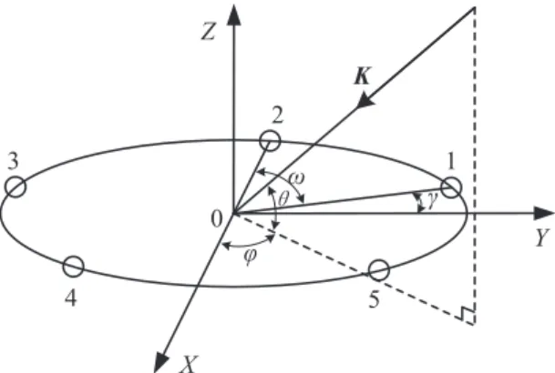
Consider a single signal impinging on a five-element UCA of radiusR. A three dimensional Cartesian coordinate system is established on the array. As shown in Fig. 1, the angleγ=18◦is used to locate the first sensor andω=72◦ is the angle between sensors. The vectorKis used to de-note the signal whose DOA is(θ,ϕ).θis the elevation angle which is in the range[0◦,90◦] andϕ is the azimuth angle which is in the range[0◦,360◦].
K
ij
Ȧ
Ȗ
©
Z
X
Y
Fig. 1.Schematic diagram of the five-element UCA interferom-eter.
Assuming a noiseless scenario and setting the origin as the phase reference point, we can represent the output of thepth sensor at timetas
xp(t) =aps(t)exp{(2πiR/λ)cos(θ)cos[ϕ−γ+ω(1−p)]}
(2)
wherep=1, . . . ,5 and i=√−1. apis the gain of the pth
sensor,s(t)is the signal andλis the wavelength of signal. In terms of the estimation accuracy, the long baseline is pre-ferred. So we measure the PD between thepth andqth sen-sor, i.e., φp,q(q=p+2. ifq=6, letq=1; ifq=7, let
q=2). Their true value can be shown as
φp,q=Arg(xp(t)/xq(t))
=−(4πR/λ)cos(θ)sin(ω)sin(ϕ−γ−ωp) (3)
where Arg(·)returns the phase angle of a complex variable. When there is no phase ambiguity, we can directly use one pair of measured PDs to estimate the DOA. Tak-ing(φ1,3,φ2,4)as an example, first, we calculate the sum and
the difference of them.
φs1234=φ1,3+φ2,4
=−(8πR/λ)cos(θ)sin(ε)sin(ω)cos(ω/2), (4)
φd1234=φ1,3−φ2,4
=−(8πR/λ)cos(θ)cos(ε)sin(ω)sin(ω/2) (5)
whereε=ϕ−γ−3ω/2. Then we construct a complex vari-able f1which is
f1=[
φd1234
−(8πR/λ)sin(ω)sin(ω/2) +i φs1234
−(8πR/λ)sin(ω)cos(ω/2)]exp(i(γ+3ω/2)) =cos(θ)exp(iϕ).
(6)
At last, DOA can be obtained as follows )
ˆ
θ=arccos(|f1|)
ˆ
ϕ=Arg(f1).
(7)
However, in most cases phase ambiguities exist. Then a clus-tering based method is introduced to solve the ambiguities [9].
First, according to the desired frequency range, the de-sired field of view (FOV), array size and (3), we are able to obtain the maximum value of the true PD and then deter-mine the range of ambiguity number by (1). Here we assume it to be in the range[−m,m]. So the total number of possible ambiguity number is 2m+1.
Then five measured pairs of PDs which are(φ1,3,φ2,4),
(φ2,4,φ3,5), (φ3,5,φ4,1), (φ4,1,φ5,2) and (φ5,2,φ1,3) are
uti-lized. Substituting the possible ambiguity numbers into (1) and adopting the similar methods in (4), (5) and (6), we can construct the complex variables f1, f2, f3, f4 and f5,
re-spectively. As we have 2m+1 ambiguity numbers, then five complex variables output five sets respectively and each set contains(2m+1)2 elements. Note that the elements with
magnitude larger than 1 should be removed.
other elements selected from the five sets respectively. So our goal is to pick out the five most clustered elements, one element from one set. That can be done like this. Set one set as a reference (e.g., the first set). For each element of the set, find the four shortest Euclidean distance to the other four sets respectively and calculate the sum of the four distances. Then we will get(2m+1)2summations. The element in the
reference set having the minimum summation corresponds to the unambiguous PD pair and can be adopted to estimate the DOA through (7). At the same time we can output the true ambiguity numbers.
It can be seen that the clustering based method needs nested loops (loop within a loop) to resolve the ambi-guities. The time complexity of ambiguity resolution is O
(2m+1)4(M−1)
where M denotes the number of sensors. It is very time-consuming and not suitable for real-time application. So we figure out a LUT method to acceler-ate it.
3. Improved Method Based on LUT
3.1 System Architecture
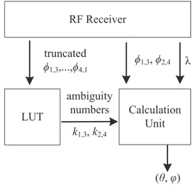
Figure 2 is the block diagram of LUT based DOA esti-mator with the five-element UCA interferometer. For ambi-guity resolution we need five measured PDs which areφ1,3,
φ2,4,φ3,5,φ4,1andφ5,2. However, one of them is redundant.
For example,φ5,2can be derived by
φ52=mod[−(φ13+φ24+φ35+φ41)−π,2π]−π (8)
where mod(·)is the modulo operator. So we only have to measure four PDs (i.e.,φ1,3,φ2,4,φ3,5andφ4,1) and each of
PDs is represented inL-bit. This can save the system cost and since the PDs are configured as the address of the table, the table size is shrunk. From the table, we look up the am-biguity numbersk1,3andk2,4instead of looking up the
even-tual DOA directly. This can bring several benefits. Firstly, Different from the DOA value which needs to be represented in large bit width, ambiguity numbers are small integers. So they can be represented in small bit width. Secondly, as the ambiguity numbers are the discrete variables, they are not sensitive to the accuracy of the measured PDs. That means if the measured PDs are represented in small bit width (e.g., N-bit andN<L), we are still able to achieve the true am-biguity numbers. So theN-bit PDs are configured as the address. When looking up the table, we truncate theL-bit measured PDs toN-bit by reserving the highN-bit. Thirdly, it is easy to find that there is no need to resolve the ambi-guities at the exact frequency of signal. If the ambiambi-guities are resolved atλr,λin (6) will be replaced byλr and (6) is
turned into
f1r=
λr
λ cos(θ)exp(iϕ). (9)
The coefficientλr/λhas no impact on the clustering based
ambiguity resolution method described in section 2. Theo-retically, the LUT method can achieve unlimited frequency bandwidth without adding the frequency component to the table address. All the above contribute to shrinking the table size.
5)5HFHLYHU
/87
&DOFXODWLRQ
8QLW
WUXQFDWHG
DPELJXLW\
QXPEHUV
Ȝ
k
k
ș
ij
Fig. 2.Block diagram of LUT based method for DOA estima-tion.
Afterk1,3andk2,4being obtained, they are sent to the
calculation unit which exerts (1), (4), (5), (6) and (7) to out-put the DOA. According to (1), (4), (5) and (6), we need to knowλand the measuredφ1,3andφ2,4. λcan be achieved
by the instantaneous frequency measurement (DIFM) [12] module in the radio frequency (RF) receiver andφ1,3,φ2,4
obtained by the fast Fourier transform (FFT) or via a phase detector [13] is represented in full bit width (L-bit). As long as they are accurate enough, the DOA estimation accuracy will be maintained. The computational cost in the calcula-tion unit is low as we can pre-calculate the constant compo-nents in (6).
3.2 Table Building
Table building is a procedure that we list all possible table addresses and for each calculate its corresponding ta-ble element. Since each PD configured as part of the address is anN-bit number, it has 2N possible values which are in the set containing elements from−πtoπwith the interval of 2π/(2N−1). Then the table address that concatenates the four truncated PDs together is a 4N-bit number and has 24N possible combinations. For each combination we will cal-culate the ambiguity numbersk1,3andk2,4with the method
described in Sec. 2. The computational cost is high. How-ever, the table is always pre-calculated and the calculation can be accelerated by the parallel technique. The table ele-ment is the combination ofk1,3andk2,4. If it is represented
byPbits, the table size will be 24NP/223MB.
at the higher frequency. From (9) we can find that lower fre-quency has a possibility to make the magnitude of f1rlarger
than 1. This f1r will be removed during ambiguity
resolu-tion. If the f1ris related to the true ambiguity numbers, then
the table will be incorrectly built. Therefore the table should be built at the frequency greater than or equal to the highest frequency within desired band. Here we choose the highest frequency.
3.3 Numerical Simulations
Obviously, we want the bit width of the table address to be small enough to shrink the table size. Paradoxically, too small bit width may lead to unsuccessful ambiguity resolu-tion. So, we conduct numerical simulations to determineN and verify the performance.
First, we define the DOA estimation error as
Kerror=arccos(Kt·Ke)
=arccos[(cosθtcosϕt,cosθtsinϕt,sinθt)
·(cosθecosϕe,cosθesinϕe,sinθe)]
(10)
where(·)denotes the inner product. Kt is the vector
asso-ciated to true DOA andKe is the vector associated to
esti-mated DOA. Subscripttanderepresent true and estimated, respectively. Suppose the table is built atR/λ=2.6. The true DOA is(30◦,60◦). The wavelength of the signal isλ
andR/λ=2 and ambiguity number is in the range[−2,2]. The PDs are acquired by 64-point FFT andL=14. Signal-to-noise ratio (SNR) varies from−5 dB to 5 dB. For each condition, 500 Monte Carlo trials are run and the trail with DOA estimation error smaller than 3◦is assumed to be one successful ambiguity resolution. The simulation results of N=4,5,6 and the direct calculation (DC) are shown in Fig. 3 (a). DC means directly using the method in Section 2 with-out the LUT method. It can be seen that small bit width of table address decrease the successful probability of ambigu-ity resolution andN=6 is a good choice since its perfor-mance is the nearly the same as the DC. So the bit width of the table address is 24. With the table element represented by 8-bit, the table size is 16MB. If the ambiguities are suc-cessfully resolved, the DOA estimation accuracy of the pro-posed method will be the same as the DC. So we leave out the accuracy comparison.
Next, we show the performance of the LUT method under wideband scenario. The simulation conditions are the same as previous except that the PDs are acquired by 128-point FFT.R/λ is varied from 0.05 to 2.6 andN=6. The root mean square error (RMSE) are depicted in Fig.3 (b). We can find that as frequency goes low, the RMSE becomes large. This is because the effective array aperture is small at low frequency. So, in practical the bandwidth cannot be too wide.
−5 0 5
0.8 0.85 0.9 0.95 1
SNR (dB)
Successful probability of ambiguity resolution
N=4 N=5 N=6
DC
0.05 0.48 0.91 1.34 1.77 2.2 2.6
10−1 100 101
R/λ
RMSE (Deg)
SNR=5dB SNR=10dB SNR=15dB
Fig. 3.DOA estimation performance under different conditions, DetermineN(top), Wideband performance (bottom).
45 30 15 0 15 30 45
45 30 15 0 15 30 45
Elevation (Deg)
Elevation (Deg)
10 20 30 40 50 60
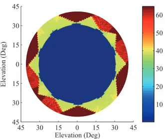
Fig. 4.The FOV of the proposed method withR/λ=2.6 and
Then we test the range of FOV of the proposed method. It is determined by the elevation angle and the higher the frequency is, the smaller the FOV will be. So we varyθat the highest frequency, i.e., R/λ=2.6. Other condition is the same as above except that SNR is fixed at 10dB. Since the FOV here is approximately a circular cone, we depict its cross section in Fig. 4.
Different colors represent different RMSEs of the DOA es-timation and their relationship is indicated by the color bar. It is easy to observe that when the elevation is in the range
[0◦,30◦]the source can be successfully resolved. The FOV is limited due to the limited value of the maximum ambigu-ity number (i.e.,m=2) and can be enlarged by increasing the value ofm. In practice,mshould be determined in the first place by the desired FOV and frequency rang.
3.4 Advantages and Disadvantage
The advantages of the propose method include ultra-high speed, ultra-high accuracy and low memory usage.
From Sec. 3.1 we see that the table size is shrunk by looking up the ambiguity numbers instead of the eventual DOA from the table. The memory usage will be lower than that of the correlative interferometer, especially for high ac-curacy wideband application. So the proposed method has the advantage of low memory usage. From the first simula-tion above, we find that when we setN=6 the successful probability of ambiguity resolution of the proposed method is nearly the same as DC. And in the proposed method the DOA estimation accuracy will be the same as the DC, if the ambiguities are successfully resolved. Since the interferom-eter has the inherent advantage of high accuracy, we draw the conclusion that the proposed method also has high accuracy.
In contrast, the accuracy of the correlative interferom-eter depends on the density of spatial grids. For some DOA estimation methods, we need to perform spatial scanning. For instance, the correlative interferometer [10] needs to cal-culate the correlative coefficient at every spatial grid and the MUSIC algorithm [4] needs to calculate the value of a cost function for every direction vector. The spatial scanning can be very time-consuming, especially for the 2-D DOA estima-tion. However, in the proposed method, the table addresses cover all possible measured PDs due to the table building method described in Sec. 3.2. So, without spatial scanning, we can look up the corresponding ambiguity numbers from the table directly.
Then the DOA can be derived by relatively small amount of calculation. So the proposed method is able to realize ultra-high speed.
However, in general, this method cannot deal with mul-tiple signals simultaneously, which is the inherent disadvan-tage of the interferometer. But we can extract other
informa-tion to separate the signals, e.g., we can tackle the multiple signals with different frequencies by spectral decomposition.
4. Practical DOA Estimator Design
and Measured Results
In this section, a practical implementation of wide-band DOA estimator is presented. We choose XC5VSX95T which is the Xilinx Virtex-5 FPGA as the processor and make it work at the clock of 200 MHz. The table is cal-culated and saved by MATLAB at the condition ofN=6, m=2 andR/λ=2.6. Then the table elements are written into a flash memory with their corresponding addresses. The flash memory we adopt is M29W128GH from Micron whose density is 16 MB.
)/$6+
(TQ (TQ
(TQ (TQ (TQ
(TQ Ȝ
7UXQFDWRU
t
t
&DOFXODWLRQ8QLWVWDJHSLSHOLQH
șij
ELW
DGGUHVV ELWGDWD
kk
)3*$
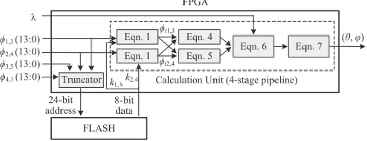
Fig. 5.Hardware design of the wideband DOA estimator.
$WU5KIPCN 1 :
2&AXCNKF
MAXCNKF
&1#AXCNKF
GNGXCVKQP
C\KOWVJ
Fig. 6.The waveform of estimator captured by Chipscope.
The hardware design is shown in Fig. 5. As the table address is in 24-bit, only the high 6-bit of each 14-bit PD are reserved by the truncator. From the flash memory we get the 8-bit data containing the ambiguity numbersk1,3 andk2,4.
Then the ambiguity numbers are sent to the calculation unit along with the 14-bitφ1,3andφ2,4. In the calculation unit,
we make full use of the parallel computation and the pipeline technique to accelerate the calculation. It has a four-stage pipeline. At the first stage, the FPGA runs two independent (1) parallelly to output the true PDsφt1,3andφt2,4,
respec-tively. At the second stage, (4) and (5) are also executed parallelly. At the third stage, the constant components (e.g.,
(8πR/λ)sin(ω)sin(ω/2)) in (6) can be pre-calculated. At last, the DOA which is represented in Q10 format in radian is achieved at the forth stage.
to the FPGA via VIO Console. The waveform captured by Chipscope is shown in Fig. 6. PD valid pulse means FPGA has detected the PDs. After 14 clock cycles, the flash memory outputs the ambiguity numbers and gives a k valid pulse. The time between the PD valid pulse and k validpulse depends on the access time of the flash mem-ory. Afterwards, FPGA executes the operations in the calcu-lation unit to output the DOA with aDOA validpulse. The measured DOA in the figure is(536/210,1073/210)radian (i.e.,(29.99◦,60.04◦)) which is approximately equal to the true DOA. There are 36 clock cycles between thePD valid pulse andDOA valid pulse. As the clock frequency being 200MHz, the estimation costs 180 ns. There is a digital sig-nal processor (DSP) based hardware implementation of the DC reported in [11]. It takes 7ms to run a estimation. That is to say our LUT based method improves the speed by 38889 times, i.e., four orders of magnitude.
In addition, the estimation speed is able to be further accelerated by two approaches. The first is to increase the clock frequency with a more powerful FPGA (e.g., Virtex-6, Virtex-7). The second is to shorten the time table lookup costs by replacing the flash memory with the random access memory (RAM) and the table elements will be transferred to the RAM during stage of the system initialization.
−30 −20
−10 0
10 20
30 −30 −20 −10 0
10 20
30 0
20 40 60 80
β (Deg) α (Deg)
Estimation error (Deg)
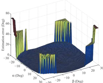
Fig. 7.Measured estimation error by spatial scanning with
R/λ=2.2.
At last, we practically test the DOA estimation perfor-mance of the estimator in a microwave anechoic chamber. The antenna array is mounted on a servo and a radiation source whose wavelength satisfies R/λ=2.2 is placed in the far-field region of the antenna. In our system, the four PDs are obtained by eight phase detectors AD8302 and then sampled by the four-channel 14-bit A/D convector AD7865.
λis measured by the DIFM. Since the servo can only swing in the vertical and horizontal plane, we define the the angle
αandβto determine the source direction.αis the angle be-tween thez-axis and the projection of soruce direction onto x-zplane.βis the angle between thez-axis and the projection
of soruce direction ontoy-zplane. we have tanα=cosφtanθ
and tanβ=sinφtanθ. The servo scans the spatial domain and the DOA estimation results are uploaded to the upper com-puter. Then we depict the estimation error in Fig. 7. It can be see the source is successfully resolved at different loca-tion in the FOV. The failed regions at the four corners are out of the FOV. It should be note that the FOV here is larger than that in Fig. 4 because of the lower frequency.
5. Conclusion
This paper introduces the LUT method to accelerate the DOA estimation with a UCA interferometer. Owing to looking up the ambiguity numbers, the table is made rel-atively small without decreasing the accuracy. The table addresses covering all possible PDs enables the method to be free of spatial scanning. Monte Carlo simulations and FPGA based hardware implementation have confirmed its ultra high speed, high accuracy, and low memory usage. This method can also be extended to other array geometry. Since the lookup table address do not contain frequency compo-nent, the estimator can easily adapt to the wideband signal by the spectral decomposition. Therefore, the proposed method will be very attractive for the engineering applications.
Acknowledgments
This work was supported in part by the National Natu-ral Science Foundation of China under Grant no. 61302141. The authors would like to thank the anonymous reviewers for the improvement of this paper.
References
[1] TUNCER, E., FRIEDLANDER, B.Classical and Modern Direction of Arrival Estimation. New York: Academic Press, 2009.
[2] CHANDRAN S.Advances in Direction-of-arrival Estimation. Lon-don: Artech House, 2006.
[3] MOSCA, E., SELENIA, S. P. A. Angle estimation in amplitude comparison monopulse systems.IEEE Transactions on Aerospace and Electronic Systems, 1969, vol. AES-5, no. 2, p. 205–212. DOI: 10.1109/TAES.1969.309906
[4] SCHMIDT, R. O. Multiple emitter location and signal param-eter estimation. IEEE Transactions on Antennas and Propaga-tion, 1986, vol. 34, no. 3, p. 276–280. ISSN: 0018-926X. DOI: 10.1109/TAP.1986.1143830
[5] ROY, R., KAILATH, T. ESPRIT-estimation of signal parameters via rotational invariance techniques.IEEE Transactions on Acoustics, Speech, and Signal Processing, 1989, vol. 37, no. 7, p. 984–995. ISSN: 0096-3518. DOI: 10.1109/29.32276
[7] LIU, Z. M., ZHOU, Y. Y. An unified framework and sparse Bayesian perspective for Direction-of-Arrival estimation in the pres-ence of array imperfections.IEEE Transactions on Signal Process-ing, 2013, vol. 61, no. 15, p. 3786–3798. ISSN: 1053-587X. DOI: 10.1109/TSP.2013.2262682
[8] JACOBS, E., RALSTON, E. W. Ambiguity resolution in inter-ferometry. IEEE Transactions on Aerospace and Electronic Sys-tems, 1981, vol. AES-17, p. 766–779. ISSN: 0018-9251. DOI: 10.1109/TAES.1981.309127
[9] WANG, Q. Research on DF based on 5-element circular array phase interferometer.Aerospace Electronic Warfare, 2009, vol. 25, no. 5, p. 33–35 (in Chinese). ISSN: 1673-2421DOI: 10.3969/j.issn.1673-2421.2009.05.010
[10] WEI, H. H., SHI, Y. G. Performance analysis and comparison of cor-relative interferometers for direction finding. InProceedings of10th
International Conference on Signal Processing. Beijing (China), 2010, p. 190–193. DOI: 10.1109/ICOSP.2010.5657185
[11] ZHANG, H., LI, W. Direction finding and position by five channels phase interferometer implement using TMS320C6711.Application of Electronic Technique, 2003, vol. 29, no, 12, p. 28–31 (in Chinese). ISSN: 0258-7998. DOI: 10.3969/j.issn.0258-7998.2003.12.008
[12] MAHLOOJI, S., MOHAMMADI, K. Very high resolution digital in-stantaneous frequency measurement receiver. InProceedings of 2009 International Conference on Signal Processing Systems. Singapore, 2009, p. 177–181. DOI: 10.1109/ICSPS.2009.43
[13] ANALOG DEVICES, AMERICA. AD8302 (datasheet).
24 pages. [online] Cited 2013-11-21. Available at: http://www.analog.com/media/cn/technical-documentation/data-sheets/AD8302.pdf.
About the Authors. . .
Yujian PANwas born in 1987. He received his M.S. degree in Electronic Science and Technology from National Univer-sity of Defense Technology in 2012. Currently he is working towards the Ph.D. degree in College of Electronic Science
and Engineering, National University of Defense Technol-ogy, Changsha, Hunan, China. His research interests include array signal processing and microwave circuit design.
Xiaofa ZHANGwas born in 1978. He received his M.S. and Ph.D. degree in Electronic Science and Technology from Na-tional University of Defense Technology in 2004 and 2007, respectively. Currently he is a teacher with College of Elec-tronic Science and Engineering, National University of De-fense Technology, Changsha, Hunan, China. His research interests include radar signal processing and microwave cir-cuit design.
Shaoyi XIEwas born in 1978. He received his M.S. degree in Electronic Science and Technology from National Univer-sity of Defense Technology in 2012. Currently he is work-ing towards the PhD degree in College of Electronic Science and Engineering, National University of Defense Technol-ogy, Changsha, Hunan, China. His research interests include radar signal processing and implementation.
Jingjian HUANGwas born in 1982. He received his M.S. and Ph.D. degree in Electronic Science and Technology from National University of Defense Technology in 2008 and 2013, respectively. Currently he is a teacher with College of Electronic Science and Engineering, National University of Defense Technology, Changsha, Hunan, China. His research interests include antenna design and structural design.