1
Design of an office building with two
variants of the roof structure
B
RUNOA
LEXANDREA
LVESG
ONÇALVESThesis submitted for partial fulfillment of the degree requirements
MASTER IN CIVIL ENGINEERING —SPECIALIZATION IN STRUCTURES DESIGN
Supervisors:
Dr. Łukasz Sadowski (Wrocław University of Technology) Dr. Rui Manuel Meneses Carneiro de Barros (FEUP)
2
Department of Civil Engineering (Porto)
Tel. +351-22-508 1901 Fax +351-22-508 1446 Rua Dr. Roberto Frias 4200-465 PORTO http://www.fe.up.pt [email protected] [email protected]
Department of Civil Engineering (Wrocław)
11 Grunwaldzki Sq. 50-377 Wrocław Building C-7
Dean’s Office: room 04, 205, 206 tel./fax +48 71 320 34 54
Dean’s Office Manager: Maria Kucharska room 502B
tel. +48 71 320 46 52 [email protected] www.wbliw.pwr.wroc.pl
Partial reproductions of this document are allowed in the condition that must be mentioned the author´s name and referred the Master in Civil Engineering - 2014/2015 - Department of Civil Engineering, Faculty of Engineering, University of Porto and University of Wroclaw, 2015.
The opinions and information included in this document represent the views of the respective author and may not accept the Editor any legal liability or otherwise for errors or omissions that may exist.
3
To my organization, persistence and hard work
After climbing a very high mountain, we find that there are many other mountains to climb Nelson Mandela
5 Acknowledgement
A special thanks for Dr. Łukasz Sadowski for the availability, support and interest shown over my period abroad and for accepting this challenge being my super-visor which gave me an enriching experience in various aspects.
I thank to Dr. Rui Barros by taking responsibility as advisor in my thesis under mobility program and for the material provided.
To Poland which gave me a fantastic life experience and well welcomed me.
A thank you to all my family, especially to my mother, father and sister for the support, patience and understanding shown in the difficult times.
To my friends, comrades in the struggle in good and bad moments. To my country which formed me as an engineer and as a man.
For all the people that I didn't mention here that helped me making this very important step in my life.
Design of extension of existing family home with two variants of the roof structure
7 Abstract
With the introduction of the Eurocodes civil engineering becomes more and more a globalized area, standardizing the design of structures and facilitating the mobility of civil engineers across the globe. Yet there are some differences in the way of conceiving projects from country to country due to the different systems that each university works with for example the construction in timber structures is rare in Portugal and very common in Poland. In Portuguese universities wood is not an exploited material justified by their little use in the country itself but still it is important to have a minimal knowledge of this material. During the academic course the student acquires a deep theoretical knowledge in various subjects and it is of utmost importance to see the connection between theory and practice in order to understand every step of a project.
This project has the objective to demonstrate a part of designing timber structures according to Eurocode 5 and to understand how the different types of wood react to different actions during its life time, to demonstrate the usually way to design (drawings) family houses in Poland and to demonstrate the whole picture of a project´s design for a single-family house linking the knowledge acquired during the academic route.
An extension of an office building with two different variants of roof structure is designed in this project, one horizontal and another vertical. Are calculated Teriva floors constituted by pre-fabricated elements. Reinforcement concrete beams are calculated in detail demonstrating all the steps for ultimate limit states and serviceability limit states according to Eurocode 2. The roof structure in timber is also designed, according to Eurocode 5, and also the study of insulation and of condensations. The dissertation ends with a brief conclusion comparing the two variants in terms of wood mass used in each one.
8
CONTENTS
1INTRODUCTION... 22 1.1.GENERAL CONSIDERATIONS ... 22 1.2.OBJECTIVES ... 22 1.3.DESCRIPTION ... 232PREFABRICATEDTERIVABEAMS(BOTHVARIANTS) ... 28
2.1.MAIN ASPECTS ... 28
2.2.STRUCTURAL ANALYSIS –ULTIMATE LIMIT STATES ... 30
2.2.1.LOADS ... 30
2.2.2.DIMENSION SELECTION ... 31
3REINFORCEDCONCRETEBEAM(EUROCODE2) ... 34
3.1.DATA ... 34
3.2.STRUCTURAL ANALYSIS –ULTIMATE LIMIT STATES ... 35
3.2.1.LOADS ... 36
3.2.2.DIAGRAMS ... 37
3.2.3.BENDING REINFORCEMENT IN THE BEAMS ... 38
3.2.4.SHEAR REINFORCEMENT IN THE BEAMS ... 40
3.2.5.DESIGN ANCHORAGE LENGTH IN TENSION FOR THE BEAM ... 43
3.3.STRUCTURAL ANALYSIS –SERVICEABILITY LIMIT STATES ... 45
3.3.1.LOADS ... 45
3.3.2.DIAGRAMS ... 48
3.3.3.CRACKING IN THE BEAM ... 51
3.3.4.MINIMUM REINFORCEMENT AREAS ... 53
3.3.5.DEFLECTION ... 54
4EUROCODE5(EC5)–PART1-1REVIEW ... 57
4.1.PHYSICAL AND MOLECULAR CHARACTERISTICS OF TIMBER ... 57
4.2.FIRE RESISTANCE ... 59
4.3.FIRE RESISTANCE ... 59
4.4.MECHANICAL CHARACTERISTICS ... 59
9
4.4.2.BENDING ... 60
4.4.3.SHEAR... 60
4.4.4.FLUENCY ... 60
4.5.EXAMPLES OF EUROCODE 5NOTATION ... 61
4.6.STRENGTH CLASSES OF TIMBER ... 62
4.7.DESIGN VALUES OF MATERIAL PROPERTIES ... 65
4.8.LOAD DURATION ... 66
4.9.MOISTURE CONTENT AND TEMPERATURE ... 68
4.10.DEPTH FACTOR –SOLID TIMBER ... 69
4.11.ULTIMATE LIMIT STATES ... 70
4.11.1.BENDING ... 73
4.11.2.SHEAR ... 75
4.11.3.TORSION ... 77
4.11.4.COMPLEX STRESS STATES ... 79
4.11.5.LATERAL BUCKLING ... 80
4.12.SERVICEABILITY LIMIT STATES ... 80
4.12.1.DEFLECTION ... 81
4.12.2.VIBRATIONS ... 83
4.13.CONNECTIONS ... 84
4.13.1.METAL DOWEL TYPE CONNECTIONS ... 87
4.13.2.PLATE BASED CONNECTIONS ... 88
4.13.3.RING BASED CONNECTIONS, SPLIT-RING... 89
4.13.4.CONNECTION USED IN THE PRESENT PROJECT ... 90
4.14.GLUE LAMINATED BEAMS ... 97
4.14.1.FABRICATION ... 98
4.14.2.DESIGN ... 98
5LOADSACCORDINGTOEUROCODE1(EC1)... 102
5.1.SNOW ... 102
5.2.WIND ... 104
6STRUCTURALANALYSIS ... 107
6.1.FIRST VARIANT ... 107
10
6.1.2.SERVICEABILITY LIMIT STATES ... 113
6.1.3.CONNECTIONS ... 114
6.2.SECOND VARIANT ... 117
6.2.1.ULTIMATE LIMIT STATES ... 117
6.2.2.SERVICEABILITY LIMIT STATES ... 125
6.2.3.CONNECTIONS ... 125
6.3.INSULATION (BOTH VARIANTS) ... 128
6.4.WALL ... 129 6.5.ROOF ... 130 6.5.1.FIRST VARIANT... 130 6.5.2.SECOND VARIANT ... 131 6.6.CONDENSATION ... 132 7CONCLUSION ... 133 8BIBLIOGRAPHY... 134 9BIBLIOGRAPHICREFERENCES ... 136 10ANNEXES ... 137
12
List of Figures
Figure 1.1 Original Architectural Plan, Author: Dr. Eng. Łukasz Sadowski Figure 1.2 Posts directly to the ground [28]
Figure 1.3 Plinth wall [28]
Figure 1.4 Rafter Roof [28] Figure 1.5 Truss Roof [28]
Figure 1.6 Aisled construction [28]
Figure 1.7 First variant, horizontal extension
Figure 1.8 Second variant, vertical extension Figure 2.1 Teriva ceiling [1]
Figure 2.2 Teriva Beams, Project Figure 2.3 Teriva Beams, Loads
Figure 2.4 Teriva Beams, Bending Moment Figure 2.5 Teriva Ceiling, Project
Figure 2.6 Teriva Ceiling, Pillar Support, Project Figure 3.1 Beam B-3, Project, First Variant Figure 3.2 Beam B-3, Project, Second Variant Figure 3.3 Teriva Beams, ULS Loads
Figure 3.4 Teriva Beams Bending, Moment Figure 3.5 Beam, ULS Load, First Variant Figure 3.6 Beam, ULS Load, Second Variant
Figure 3.7 Beam, ULS Bending Moment, First Variant Figure 3.8 Beam, ULS Bending Moment, Second Variant Figure 3.9 Beam, ULS Shear Force, First Variant Figure 3.10 Beam, ULS Shear Force, Second Variant
Figure 3.11 Beam cross-section (M>O), Rectangular Stress Distribution, ULS [3] Figure 3.12 Beam Cross-Section, Project
Figure 3.13 Beam Cross-Section, Project
Figure 3.14 Teriva Beams, Frequent Combination Bending Moment Figure 3.15 Loads, Frequent Combination, First Variant
Figure 3.16 Loads, Frequent Combination, Second Variant Figure 3.17 Bending, Frequent Combination, First Variant
13 Figure 3.18 Bending, Frequent Combination, Second Variant
Figure 3.19 Shear, Frequent Combination First Variant Figure 3.20 Shear, Frequent Combination, Second Variant
Figure 3.21 Teriva Beams, Quasi Permanent Combination Shear Force Figure 3.22 Quasi Permanent Combination, First Variant
Figure 3.23 Quasi Permanent Combination, First Variant Figure 3.24 Bending, Quasi Permanent, First Variant Figure 3.25 Bending, Quasi Permanent, Second Variant Figure 3.26 Shear, Quasi Permanent First Variant Figure 3.27 Shear, Quasi Permanent Second Variant Figure 4.1 Tree trunk cross-section [16]
Figure 4.2 Examples of Eurocode5 Notation Figure 4.3 Examples of Eurocode5 Notation Figure 4.4 Examples of Eurocode5 Notation Figure 4.5 Hardwood [6] [14]
Figure 4.6 Softwood [6] [13] Figure 4.7 Timber beam, ULS [9] Figure 4.8 Direction of Grain [7]
Figure 4.9 Limits Compression Widths [5]
Figure 4.10 Effective area of compression [5] Figure 4.11 Compressive stresses at an angle [5]
Figure 4.12 fc,a,d / fc,0,d &a°
Figure 4.13 Stress in different axis [5]
Figure 4.14 Shear parallel to the grain [10] Figure 4.15 Shear perpendiculars to the grain [10] Figure 4.16 Variation of cross-section[5]
Figure 4.17 Torsion [5]
Figure 4.18 Components of deflection [18] Figure 4.19 Variable Height [5]
Figure 4.20 Timber to timber connection
Figure 4.21 Timber to timber connection – nail plate Figure 4.22 Timber to plywood connection
14
Figure 4.23 Timber to heavy gauge steel connection Figure 4.24 Timber to dowelled fin
Figure 4.25 Half-lap joint Figure 4.26 Frame joint
Figure 4.27 Tenon joint Figure Figure 4.28 Cogging joint
Figure 4.29 Connection group 1 Figure 4.30 Connection group 2 Figure 4.31 Friction force [19]
Figure 4.33 Metal bolts cross-section Figure 4.34 Metal bolts 3d view
Figure 4.35 Examples of plates [22] Figure 4.36 Ring connection [23]
Figure 4.38 –Single shear connection Figure 4.39 – Double shear connection Figure 4.40 - Overlapping nails [5]
Figure 4.41 – (a) Nailing perpendicular to grain and (b) slant nailing [5] Figure 4.42 Bridge in Sneek (Netherlands) [24]
Figure 4.43 Glulam timber cycle [25]
Figure 4.44 Horizontal and vertical glulam cross-section
Figure 4.45 Glued Laminate cross-section in same class and different classes [26] Figure 4.46 Glulam timber cross-section [5]
Figure 5.47 Snow Map of Poland [4]
Figure 5.48 Exposure categories coefficients [4] Figure 6.49 Horizontal Extension, First Variant, Project Figure 6.50 Roof Battens, ULS Loads
Figure 6.51 Roof Battens, ULS Bending Moment Figure 6.52 Loads ULS, First Variant
Figure 6.53 Diagram of Bending Moment ULS, First Variant Figure 6.54 Diagram of Axial Force ULS, First Variant Figure 6.55 Connection 1, First Variant
15 Figure 6.57 Vertical Extension, Second Variant, Project
Figure 6.58 Roof Battens, ULS Bending Moment Figure 6.59 Roof Battens, ULS Bending Moment Figure 6.60 Loads ULS, Second Variant
Figure 6.61 Diagram of Bending Moment ULS, Second Variant Figure 6.62 Diagram of Axial Force ULS, Second Variant Figure 6.63 Connection 1, Second Variant
Figure 6.64 Connection 1, Second Variant
Figure 6.65 Insulation, External Wall Isolation, Project Figure 6.66 Insulation, Roof Insulation, First Variant, Project Figure 6.67 Insulation, Roof Insulation, Second Variant, Project Figure 6.68 Psychometric diagram [27]
16
List of Tables
Table 2.1 Balance of loadings ULS, Teriva beams
Table 2.2 Maximum values of the bending moments per one rib in the roof Teriva [2] Table 2.3 Teriva dimensions [2]
Table 3.1 Concrete Data
Table 3.2 Balance of loadings ULS, Teriva Beams Table 3.2 Actions Categories [4]
Table 3.3 Balance of loadings, Frequent Combination, Teriva Beams Table 3.4 Actions Categories [4]
Table 3.5 Balance of loadings, Frequent Combination, Teriva Beams Table 3.6 Balance of loadings, Quasi Permanent Combination, Teriva beams
Table 3.7 Recommended values of Wmax [3]
Table 3.8 Maximum bar diameters for crack control [3] Table 3.9 Maximum bar spacing for crack control [3] Table 3.10 K values [3]
Table 4.1 Strength Classes of Timber [7] Table 4.2 Strength Types of Timber [18]
Table 4.3 Recommended cross-sections dimensions according to PN-EN 1313-1 [8]
Table 4.4 Recommended Partial Factors M (Fundamental Combinations) [5]
Table 4.5 Values of Kmod[5]
Table 4.6 Values of Kdef [5]
Table 4.7 Percentage of Moisture Content & Strength [5] Table 4.8 Service Classes of Timber [5]
Table 4.9 Limits Compression Widths [5]
Table 4.10 kcr values [5]
Table 4.11 Examples of permissible deflections for beams [5]
Table 4.12 Permissible deflections wfin[5]
17 Table 4.14 Spacing parallel to grain in a row and perpendicular to grain between rows [5]
Table 4.15 Edge and end distances [5]
Table 4.16 Angle between nails and edges/ends [5] Table 4.17 Minimum spacing or end/edge distance [5] Table 4.18 Properties of glulam [15]
Table 5.19 Recommended values of Ce for different topographies [4]
Table 5.20 Snow load shape coefficients [4]
Table 5.21 sKvalues [4]
Table 6.22 Balance of loadings ULS, First variant of roof structure
Table 6.23 Kmod values [5]
Table 6.24 Load & 𝐾𝑑𝑒𝑓, 𝑢𝑖𝑛𝑠𝑡, 𝑢𝑓𝑖𝑛 values [5]
Table 6.25 Balance of loadings ULS, Second variant of roof structure
Table 6.26 Kmod values [5]
Table 6.27 Load & 𝐾𝑑𝑒𝑓, 𝑢𝑖𝑛𝑠𝑡, 𝑢𝑓𝑖𝑛 values [5]
Table 7.1 Total Wood Mass, First Variant Table 7.2 Total Wood Mass, Second Variant
19 Symbols and abbreviations
A s - Area of beam
b - Breadth of beam h - Height of beam L - Length of member i - Radius of gyration I - Second Moment of Area
Wy, Wz - Elastic modulus about y-y and z-z respectively
l – Span
Md - Design moment
G - Permanent action Q - Variable action
σm,d - Design normal bending stress
fm,k - Characteristic bending strength
fm,d - Design bending strength
γG - Partial coefficient for permanent actions
γQ - Partial coefficient for variable actions
γM - Partial factor for material properties, modelling uncertainties and geometric variations
kmod - Modification factor to strength values, allowing for load duration and moisture content
ksys - Load sharing factor
kinst - Instability factor for lateral buckling
E0,05 - Fifth percentile value of modulus of elasticity
Emean - Mean value of modulus of elasticity (parallel) to grain
uinst - Instantaneous deformation
uinst,G - Instantaneous deformation due to a permanent action G
uinst,Q,1 - Instantaneous deformation for the leading variable action Q1
ufin - Final deformation
ufin,G - Final deformation due to a permanent action G
ufin,Q,1 - Final deformation for the leading variable action Q1
kdef - Deformation factor
wcreep - Creep deflection
wc - Camber deflection
winst - Instantaneous deflection
wnet,fin - Net final deflection
wfin - Final deflection
20
uv - Shear deflection
F90,d - Design bearing force
L - Length of bearing
σc,90,d - Design compression stress perpendicular to grain
fc,90,k - Characteristic compression strength perpendicular to grain
L ef - Effective length of column
λy, λz - Slenderness ratios about y–y and z–z axes
λrel,y, λrel,z - Relative slenderness ratios about y–y and z–z axes
N - Design axial force
σc,0,d - Design compression stress parallel to grain
fc,0,k - Characteristic compression strength parallel to grain
fc,0,d - Design compression strength parallel to grain
σm,y,σm,z,d - Design bending stresses parallel to grain
fm,y,d, fm,z,d - Design bending strengths parallel to grain
21
22
1
INTRODUCTION
1.1. GENERAL CONSIDERATIONS
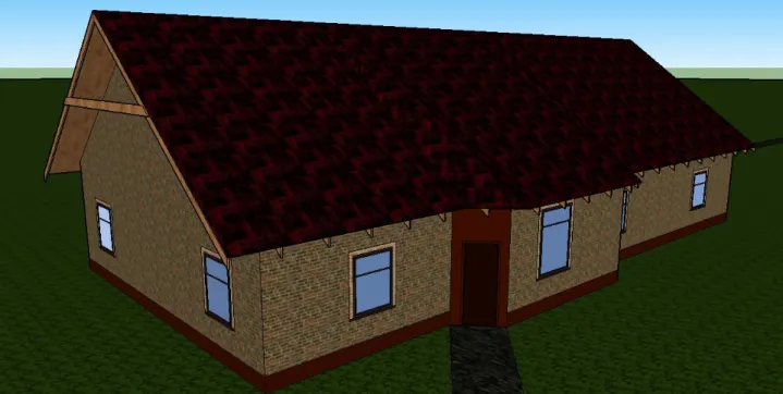
The objective of this thesis is to design two different extensions of an existing house, a horizontal extension corresponding to the first variant (see figure 1.7) and a vertical extension corresponding to the second variant (see figure 1.8).
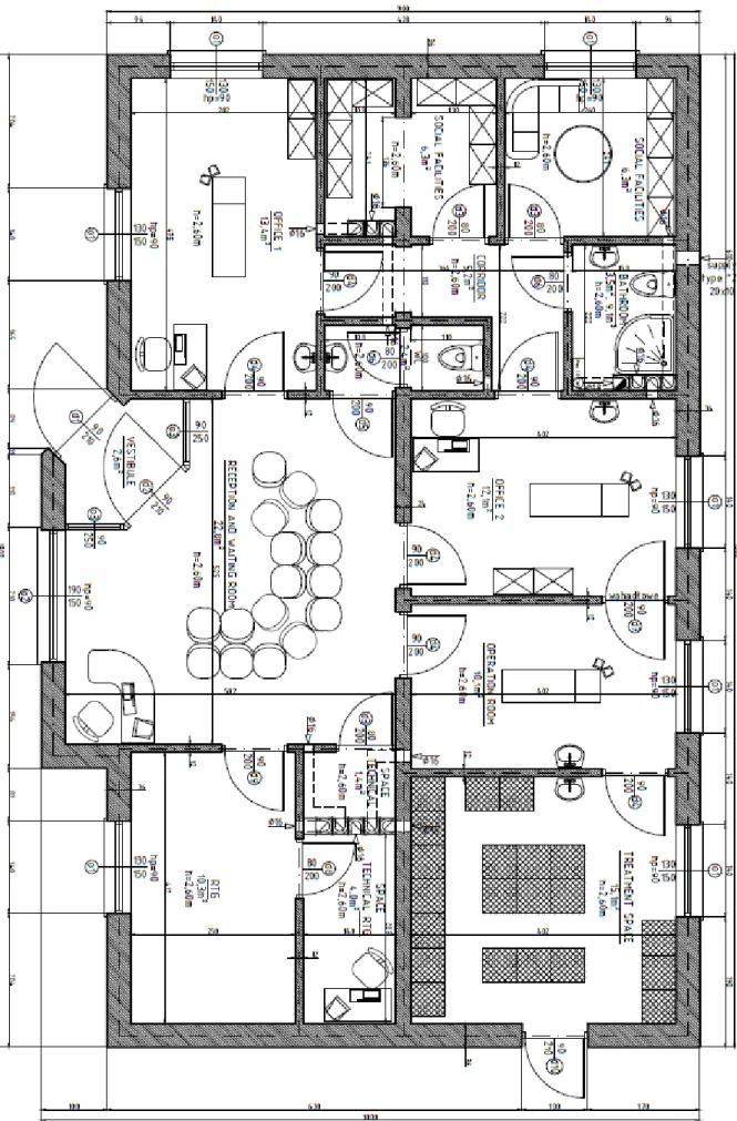
Both extensions are projected from an initial architectural plan provided by Dr. Łukasz Sadowski as shown in Figure 1.1. However, it was necessary to make some initial arrangements of the compartments and measures of the house in order to be considered as a family/office building (see design drawings at the end- annexes).
Once the plant is completed some decisions respectively to the materials that will be forming the house´s structure have to be made. A prefabricated Teriva ceiling, very common in Poland, is supporting the roof structure in the first variant and supporting the second floor in the second variant. This ceiling is formed by prefabricated beams that support several hollow blocks made of concrete that posteriorly are covered by a concrete layer in order to make a smooth surface. The Teriva ceiling is supported by a secondary beam also supported by a continuous wall formed of Ytong blocks. As for the roof, it is designed with timber elements making it possible explore timber structures according to Eurocode 5. Timber is also a very common material in Poland especially for roofs.
1.2. OBJECTIVES
The objectives of this thesis are to explore the main aspects of designing timber elements according to Eurocode 5 for ultimate limit states and serviceability limit states, to design in detail a reinforcement concrete beam according to Eurocode 2 in such way that all the aspects necessary to analyze any concrete structure are covered as for ultimate limit states and for serviceability limit states. To design a prefabricated Teriva ceiling (very common in Poland) using polish catalogs, to determinate the wind and snow actions on the structure according to Eurocode 1 taking into account the location (Warsaw, Poland) and to calculate the isolation with the polish limit values of transfer heating and the verification of condensation inside the house represent the main design tasks developed under this project. This thesis also has the objective to design the whole project of a family home, such as the foundations plants, ceilings plants, roof plants, cross-sections views, details of particular areas, quantities and types of steel and wood and description of the materials used to build the houses.
23
1.3. DESCRIPTION
Respectively to the ceiling (chapter 2), an initial consideration of live and dead loads is made according to Eurocode 1 and to the permanent loads of materials which form the ceiling. Once the necessary resistance values are calculated, the dimensions of the prefabricated elements are selected from a Polish catalog.
Due to the architectural plan, a reinforced concrete beam is designed in order to overcome a span of 4,30 m for both variants (see design drawings at the end). With this in chapter three, it is analyzed in detail according to Eurocode 2 the ultimate limit states (ULS) and serviceability limits states (SLS) for the reinforced concrete beams. To prevent the beam from collapse (ULS), it is calculated the steel necessary to resist to bending and shear force and the respective anchorage length in tension. To ensure a good behavior of the beam in service (SLS) it is controlled the cracking, deflection and minimum reinforcement in such way that unpleasant problems will appear during the life time of the structure. These analyze cover all the fundamental areas of concrete structures, according to Eurocode 2.
Related to the roof structure in timber, two different variants of roof are considered. In pre-1200 the building’s structures gained rigidity by placing their timber post directly to the ground. However, over the years it was developed a new technique where the timber posts jointed to a timber beam supported by a plinth wall. This became known as “framed wall”.
Figure 1.2 Posts directly to the ground [28] Figure 1.3 Plinth wall [28]
A “box frame” consists of framed walls, connected at bay intervals by cross tie beams designed to support the load of the rafter roof. Sometimes, instead of a rafter roof there is a truss roof where the elements are structurally united within each cross frame and purlins are used in this case. The truss roof allows for a better distribution of loads along the framed walls.
24
Figure 1.4 Rafter Roof [28] Figure 1.5 Truss Roof [28]
In order to provide a better utility of the space, the aisled constructions are very often used where the wall posts become internal and the aisles are roofed over with lean to roofs at an angle matching the main roof. In these situations, “window frames” and “door frames” were a part of the timber frame itself different from the way it is build nowadays.
Figure 1.6 Aisled construction [28]
In this particular project the case which is studied is a rafter roof related for the first roof variant (horizontal extension) and the aisled constructions related to the second roof variant (vertical extension).
In chapter four it is explored the construction in timber elements. It is made the respective calculations for the roof in study and it is presented the description of the loads derived by wind and snow, according to Eurocode 1. Related to timber structures, an introduction about physical and molecular characteristics of wood is described in order to give a basic concept about types of timber, how timber elements react to fire, to bending, axial and shear force and to fluency. It is demonstrated some examples of notations according to Eurocode 5, some design values of the material properties and the different classes of timber strength depending on softwood or hardwood. Some important coefficients are explored as the Kmod and Kdef coefficients related to the duration of the loads, the coefficient Ktemp related to the moisture content of the wood and related to the temperature which affects the mechanical properties of the structure elements and the depth factor
25
h
K related to the volume of the elements (the larger the volume of a timber element the bigger it is
its loss resistance). In order to prevent timber structures from collapse it is explored the ultimate limit states according to Eurocode 5 for torsion, bending, shear, bending plus axial forces simultaneously and lateral buckling. For serviceability limit states deflections and vibrations are analyzed. Different types of connections are shown as metal dowel type connections (screws and nails), plate based connections and ring based connections. A deeper look is made to connections by screws because these are the ones used in this particular project. It is demonstrated how to calculate its moment, axial, shear and shear plus axial resistance including the definition of the correct spaces and angles between edges/ends and screw’s spaces. An introduction for glue laminated timber elements it´s also demonstrated. It is presented how glulam timber is made and the basic concept to calculate these elements. In the last part of this chapter it is demonstrated all the calculations for the roof structure in each variant.
In chapter five it is calculated the isolation for the wall, roof and foundation in each variant and also it´s made the verification of condensation in order to prevent from serviceability problems.
The project culminates with a brief conclusion making the most affordable choice between the two roof structure variants.
26
27 Figure 1.7 First variant, horizontal extension
28
2
PREFABRICATED
TERIVA
BEAMS
(BOTH
VARIANTS)
2.1. MAIN ASPECTS
Teriva ceilings are very common in Poland. They are constituted by hollow blocks supported by reinforced concrete beams-ribs. The beams-ribs are load bearing structural elements from the ceiling, and then to the wall.
These ceilings have capacity to support live loads around 4,0, 6,0 and 8,0 kN/m2, depending of the dimensions of the blocks and beams, depending on the amount of steel used on the beams and of the span. The constructions of Teriva ceilings are performed without the need of heavy equipment which minimizes the cost of the building, with high efficiency of the works due to the prefabricated elements that are used. It doesn´t need all formwork (only in the support beams) what also it decreases the final cost and it is characterized for its good qualities related to thermal and acoustic insulators. On the other hand, Teriva ceilings are characterized by their own high thickness due to the pre-fabricated elements like the hollow blocks.
29 The beam-ribs that support the hollow blocks are supported in another continuous beam (made in the local) which lays in the structural wall. This support in the wall should have at least 8 cm to ensure the minimum effective contact area due to the stress created by the loads. In order to the stress to be distributed evenly to the wall it is recommended a prefabricated element called edge profiles which supports the continuous beam in the wall. All must be concreted together to ensure a healthy behavior of the ceiling. Before putting the concrete over the ceiling, all contamination must be removed and all the components should be cleaned with water, such as hollow blocks elements and joists. The ceiling concreting must be done in the direction of the beams and if the delivering is made by means of wheelbarrows it is necessary to place platforms laid out at the right angle to the beams in such way that all empty space must be full filled for a good concrete consolidation and it´s also important that during these task samples are taken, in order to the concrete quality. For the platform´s cross-section sizes it´s recommended at least 3,8 cm thickness and 20 cm of width and it´s also important to refer that the edges of the platform must be prevented with skirting boards for a good handling of the wheelbarrow.
During the construction process of the ceiling there should exist temporary supports (braces) until the concrete reaches its own characteristics as projected in such way that unpleasant deflections won´t appear. These supports normally are placed with 2 m distance (maximum) and must be under the beams and not under the blocks. It´s important to refer that for spans bigger than 6,4 m a reverse deflection of 15 mm is necessary to support its own weight.
It´s recommended to use reinforcement in the upper fibers of the cross-section to absorb tensions of temperature changes and avoid cracking. The reinforcement must be formed by a grid of steel A-IIIN welded in the connections and normally spacing 20 cm.
Relating to the project itself there are some aspects important to take into account. Each floor must be designed by the manufacturer and should be present in the project the drawings of the ceiling elements. Any change that may be made in the project must be informed and discussed with the constructer. Otherwise it´s a risk that can result in several problems during many years. Consequently the design must specify all the dimensions of the ceiling elements, such as the blocks and beams, and a special attention for the edges near the structural wall which depending on the distance of the last beam it´s possible to adopt various solutions. In this project, it was designed a extension of the supporting beam located along the structural wall in such way that makes it possible to fit all the elements one to each other with the correct designed dimensions. Another important aspect that must be present in the project is the way of making holes in the ceiling installations. This may be made in the blocks and not on the beams and if the holes are small then just the block itself is perforated and it won´t be necessary to pay any special attention but often the holes are spaced along the beams and in this case it´s necessary additional beams to support the ceiling in this area. The design also must specify the way of making the wall beams which support the ceiling. Here it’s important to transfer the stress created by the loads in uniform way to the structural wall. The ceiling can´t be directly supported on the wall otherwise the top of the wall will break. A beam normally with 4 steel rods with 12 mm of diameter must be designed for this place.
30
2.2. STRUCTURAL ANALYSIS –ULTIMATE LIMIT STATES
In this project, there are different spans relating to the Teriva beams. The biggest span has 5,3 m like presented in the figure 2.2.
Figure 2.2 Teriva Beams, Project
2.2.1. LOADS
Below are presented the typical balance of permanent and live loadings
Table 2.1 Balance of loadings ULS, Teriva beams
Dead (permament loading) Calculation gk 𝛄Gj,
sup
gd
[𝐊𝐍 𝐦] Self-leveling cementious underlayment
( 3 cm ) γslcu [KN/m^3]* 0,03 m*0,6 m 0,308 1,35 0,51
Protective layer - PCV foli 0,02 kN/m^2*0,6 m 0,012 1,35 0,02
Isolation - mineral wool ( 35 cm ) γpvc * 0,35 m*0,6 m 0,005 1,35 0,006
Hollow Block 𝑞k= 0,16 KN/unit 𝑞k= 0,9 KN/m 0,9 1,35 1,3
Reinforced concrete slab+beam
(41,25 cm2 ) γc [KN/m^3]* 0.004125*0,6 m 0,072 1,35 0,084
Cementious plaster work (1,5 cm ) γcpw [kN/m^3] * 0,015 m*0,6 m 0,19 1,35 0,23
SUM 1,61 2,31
Live (variable loading) qk 𝛄Q,1 qd
31
2.2.2. DIMENSION SELECTION
Below there are the permanent + variable load for the TERIVA beams in the project
Figure 2.3 Teriva Beams, Loads
Figure 2.4 Teriva Beams, Bending Moment
MMAX= 16.6 KNm VMAX= 12.3 KN
Once Teriva ceiling is constituted by prefabricated elements there is also a catalog with the bending moment resistance of each ceiling according to the span, size of elements and loading which must be consulted to select the correct one. On the table 2.2, it is presented a part of the catalog for Teriva 1 type and it´s possible to verify that it has the necessary resistance for a bending moment of 16.6 KNm with 5,4 m of span.
32
Table 2.2 Maximum values of the bending moments per one rib in the roof Teriva 1 [2]
Modular Span Design Span
Moment of the Design Load [KNm] Shear of the Design Load [KNm] 2,4 2,37 6,843 13 2,8 2,77 6,843 13 3,0 2,97 6,843 13 3,4 3,37 6,843 13 3,6 3,57 6,843 13 3,8 3,77 8,059 13 4,2 4,17 9,374 13 4,4 4,37 10,789 13 4,8 4,77 12,303 13 5,0 4,97 13,917 13 5,4 5,37 15,630 13 5,6 5,57 17,442 13 6,0 5,97 19,354 13
Once chosen the type of Teriva ceiling (Teriva 1) to the project, it follows the selection of dimensions of the ceiling like is presented in the table below
Table 2.3 Teriva 1 dimensions [2]
Ceiling type Ceiling span [m] Joists gauge [m] Ceiling construction height [m] Top concrete layer thickness [mm] Ceiling construction weight [kN/m2] TERIVA 4,0/1 2,4 ÷ 7,2 * 0,60 0,24 30 2,68 TERIVA 4,0/2 2,4 ÷ 8,0 0,60 0,30 40 3,15 TERIVA 4,0/3 2,4 ÷ 8,6 0,60 0,34 40 3,40 TERIVA 6,0 2,4 ÷ 7,8 0,45 0,34 40 4,00 TERIVA 8,0 2,4 ÷ 7,2 0,45 0,34 40 4,00
33 Figure 2.5 Teriva Ceiling, Project
Important Note: In order to give support to the timber pillar of the second variant, it is necessary to locate three Teriva beams under each pillar to give the proper support.
MMAX= 50,2 KNm → MResis.= 17,422 ∗ 3 = 52 KNm
34
3
REINFORCED
CONCRETE
BEAM
(EUROCODE
2)
Apart from the fact that in this project the concrete is just related for a simple supported beam, it is important to refer that in the past few years the construction in concrete structures has been developing and increasing. The quality and durability of the concrete have been explored in such way to predict unpleasant problems in the concrete structures. The causes of concrete problems can be several as excess of the loads comparing from the loads design in the project, errors of units and calculations, corrosion of the steel, thermal variations, biological attacks, incompatibility of the materials, among other reasons. The consequences of this errors may put in risk the own stability of the structure and sometimes driving to collapse overpassing the ultimate limit states and also may result some serviceability problems, such as cracking and deflections in the concrete. In order to avoid these problems a detailed design is made for the reinforced concrete beam in study.
3.1. DATA
Due to the architectural plan it is necessary to design a beam with 25 cm of width and 25 cm of height like presented on figure 3.1 (B-3). This reinforced concrete beam supports the Teriva beams.
35 From Eurocode 2 and Eurocode 1, the following data was selected (see table 3.1).
Table 3.1 Concrete Data
𝐟𝐜𝐤,𝐜𝐮𝐛𝐞 [𝐌𝐏𝐚] 𝐟𝐜𝐭𝐦 [𝐌𝐏𝐚] 𝐟𝐲𝐤 [𝐌𝐏𝐚] 𝐪𝐤 [𝐊𝐍/𝐦𝟐] 𝛏𝐞𝐟𝐟,𝐥𝐢𝐦 [𝐀𝐈𝐈𝐈𝐍] 𝐥 [𝐦] 𝐡 [𝐦] 𝐛 [𝐦] 25 2.2 500 1.5 0.5 4.2 0.25 0.25
For the ultimate limit states, according to Eurocode 2, it´s adopted 1,5 as a safety factor value for concrete and 1,15 for steel. Improper compaction, inappropriate curing, uncertainty in the properties of the ingredients when they are mixed are some of the reasons that explain the biggest safety factor of the concrete comparing with the safety factor of the steel. As for the steel, the uncertainties of variation in strength of the reinforcement are small so it´s not necessary such a large safety factor like for the concrete.
Applying the safety factors from Eurocode 2, the design values which will be taken into account are determinate:
fyd = fyk
γs =
500
1.15= 434.78 MPa → fyd = 434.78 Mpa eq. (3.1)
fck,cube = 25MPa → fck = 20MPa
fcd = αccfck γc = 1 ∗
20
1.5= 13.33MPa → fcd = 13.33Mpa eq. (3.2)
3.2. STRUCTURAL ANALYSIS –ULTIMATE LIMIT STATES
Limit states is a state from which it is considered when the structure is no longer able to perform the duties that are assigned to. The calculations to ensure the safety of structures must be made based in certain limit states which stabilizes a limit value for the applying forces. Posteriorly the limit states must be compared with the actual forces applied on the structure in such way that the resistance stress won´t be exceeded. Apart from the fact that in this particular project it will not be analyzed all parts of the limit states, it is important to refer all the areas related to SLS as bending moment resistance (simply and composed), shear resistance, torsion resistance, puncture resistance, buckling, balance and fatigue.
36
3.2.1. LOADS
Eurocode 2 divides the loads in three groups as the permanent loads, live loads and accidental loads. The permanent loads have constant values or almost constant during the whole life of the structure as the own weight of structural elements (structural or not), fixed equipment weight, earth pressures, prestressing, retraction, creep of concrete, settlements of the supports among others. The live loads are variable during the structure´s life as overloads and their dynamic effects, wind, earthquake and temperature variations, among others. Finally, the accidental loads have a low probability of occurring during the life of the structure and the loads are such as explosions, fires, vehicle crashes among others.
Table 3.2 Balance of loadings ULS, Teriva Beams
Balance of loadings (typical) – Teriva Beams supported on the beam to be calculated (l=5,4m)
Dead (permanent loading) Calculation gk 𝛄Gj,
sup
gd
[𝐊𝐍 𝐦]
Self-leveling cementious underlayment
( 3 cm ) γslcu [KN/m^3]* 0,03 m*0,6 m 0,308 1,35 0,51
Protective layer - PCV foli 0,02 kN/m^2*0,6 m 0,012 1,35 0,02
Isolation - mineral wool ( 35 cm ) γpvc * 0,35 m*0,6 m 0,005 1,35 0,006
Hollow Block 𝑞k= 0,16 KN/unit 𝑞k= 0,9 KN/m 0,9 1,35 1,3
Reinforced concrete slab+beam
(41,25 cm2 ) γc [KN/m^3]* 0.004125*0,6 m 0,072 1,35 0,084
Cementious plaster work (1,5 cm ) γcpw [kN/m^3] * 0,015 m*0,6 m 0,19 1,35 0,23
SUM 1,61 2,31
Live (variable loading) qk 𝛄Q,1 qd
37
3.2.2. DIAGRAMS
Below there are the permanent + variable load for TERIVA beams supported on the beam to be calculated
Figure 3.3 Teriva Beams, ULS Loads
Figure 3.4 Teriva Beams Bending, Moment
MMAX= 10.5 KNm RMAX= 9,8 KN
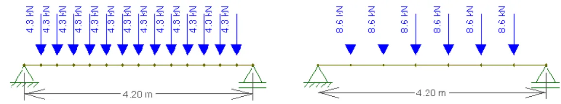
Below there are the loads for the beam (B-3) to be calculated.
38
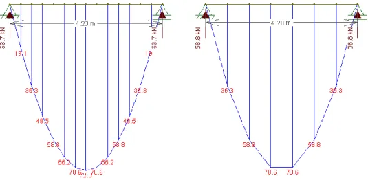
Figure 3.7 Beam B-3, ULS Bending Moment, First Variant Figure 3.8 Beam B-3, ULS Bending Moment, Second Variant
MMAX= 72.0 KNm
Figure 3.9 Beam B-3, ULS Shear Force, First Variant Figure 3.10 Beam B-3, ULS Shear Force, Second Variant
VMAX= 63.7 KNm
The span of the beam B-3 is 4,20 m due to the architectural plants. Like it is possible to verify on the drawings (annexes), in the plant is located a missing space to support the Teriva beams. The span of 4.20 m was chosen in such way to find two possible supports to be analysed as a simple supported beam.
3.2.3. BENDING REINFORCEMENT IN THE BEAMS
The calculation of the bending moment resistance of the reinforced concrete sections is based in some principles such as the geometry of the sections that should remain flat before and after the load, the tension on the steel is the same extension that exist in the concrete surrounding it, the resistance of the concrete on the traction fibers is not taken into account due the weak behavior of the concrete when submitted to traction, the stress in the compressed area of the concrete
cross-39 section is calculated using the stress-strain design diagram and the tension on the steel that reinforce the concrete is obtained also through the design diagrams.
Figure 3.11 Beam cross-section (M>O), Rectangular Stress Distribution, ULS [3]
MMAX = 72 KNm a1 = 15 mm, b = 250 mm, h = 250 mm, d = 235 mm ms = MSd fcd b d2 eq. (3.3) = 72 13.3 ∗ 103∗ 0.25 ∗ 0.2352 = 0.36671 ξeff = 1 − √1 −2 ηms eq. (3.4) = 1 − √1 −2 10.36671 = 0.4837
ξeff = 0.4837 < ξeff,lim = 0.5 (OK)
40
As verified, no compression reinforcement is required. Proceeding to the determination of the necessary area of reinforcement in the concrete cross-section, it comes:
As1 = ξeff η fcd b d fyd eq. (3.5) = 0.4837 ∗ 1 ∗13.33 ∗ 10 3∗ 0.25 ∗ 0.235 434.78 ∗ 103 = 8.8 cm2
Checking the minimum reinforcement
As1 > { 0.26 ∗ fctm∗ bt∗ d fyk eq. (3.6) = 0.26 ∗ 2.2 ∗ 103∗ 0.25 ∗ 0.235 500 ∗ 103 = 0.67cm2 0.0013 ∗ bt∗ d eq. (3.7) = 0.0013 ∗ 0.25 ∗ 0.235 = 0.76cm2
In the cross section As1required = 8.8 cm2. For this reason it is placed 5𝛟16 (10.05 cm2) for the beam (both variants) as shown on figure 3.12
Figure 3.12 Beam Cross-Section, Project
3.2.4. SHEAR REINFORCEMENT IN THE BEAMS
In elements submitted to bending forces usually the calculation of the reinforcement is made in such way that the shear force resistance is not the first condition factor for collapse but where the bending resistance must be the condition factor. In other words, the collapse must occur by bending in first place and not by shear to ensure a ductile behavior from the concrete element. In this way it is possible to anticipate the collapse through the symptoms of a normal bending as the cracking in
41 the concrete due to the high tension in the fibers and the deformations which are possible to see in naked eye.
Eurocode 2 considers three resistances of shear force which must be verified: resistance of the shear force without reinforcement, VRd,c, maximum value of the shear force that can be resisted without crush of fictitious concrete strut, Vrd,max, and the resistance of the shear force with reinforcement, VRd,s.
Sometimes the shear resistance of the own concrete, VRd,c, is enough to ensure the necessary resistance of the element. However, every concrete beam must have the minimum reinforcement for shear resistance, Vrd,cmin, to ensure the ductile behavior like described before.
In this project it is assumed θ = 45°.and α = 90°.
At first, it is necessary to check the shear load bearing capacity of the cross section related to concrete failure VRd,max > VEd,d design shear force.
VRd,max = αcw bw fcd z υ 1
ctgθ + tgθ eq. (3.8)
υ = 0.6 (1 − fck
250) , αcw = 1, z = 0.9 d
Checking the self-resistance of the beam to the design shear force VRd,c < VEd,d.
VRd,c = [CRd, c ∗ k (100 ρlfck)13 + 0.15σcp] bw d eq. (3.9) ≥ (0.0035 k32 f ck 1 2 + 0.15 σ cp) bwd k = 1 + √200 d < 2 CRd = 0.18 γc =0.18 1.5 ρl = Asl(tensile) s d < 0.02
The spacing between the stirrups is calculated in so that shear load bearing capacity of cross-section related to the transversal reinforcement VRd,s= VEd,d design shear force.
VRd,s =Asw
s z fywdctgθ eq. (3.10)
42
ρsw = Asw
s bw , ρsw,min =
0.08 √fcd
fyk eq. (3.11)
And check the maximum spacing in transversal direction s < smax
smax = 0.75 d (1 + ctgα) ≤ 600mm for stirrups eq. (3.12)
In order to calculate VRd,c, table 3.3 shows the calculations of the measure of the longitudinal designed tensile reinforcement in mm2 of the beam for both variants.
Table 3.3 Stirrups calculation
DATA ASSUMPTION STIRRUPS
fck (Mpa) 20 2 arms ϕ6
bw (mm) 250 Asw=2ϕ6 [mm^2] 56,54
d (mm) 235 fywd [Mpa] 434,78
σcp 0
Asl (tensile) [mm^2] 1005 CALCUTATION S
ctgθ 1 s rqd [mm] 247
VEd,d [KN] 63.7 It is assumed that the effective trasversal spacing is
CHECK Vrd,max and Vrd,c s [mm] 200
Vrd,max [KN] 129.72
Vrd,max > VEd,d true CHECKING LIMIT
Vrd,c [KN] 27,1 Checking Smax
Vrd,cmin [KN] 8 S<Smax true
Vrd,c > Vrd,cmin true s<600mm true
check ρsw
k (<=2) 1,922 true ρsw<ρsw,min true
ρl (<0,02) 0,013697 true ρsw 0,005381
CRd,c 0,12 (γc=1,5) ρsw,min 0,000366
43 Figure 3.13 Beam Cross-Section, Project
3.2.5. DESIGN ANCHORAGE LENGTH IN TENSION FOR THE BEAM
[3] According to Eurocode 2, the design anchorage length lbd is characterized for the effect of the form of the bars assuming adequate cover, α1, for the effect of concrete minimum cover, α2, for the effect of confinement by transverse reinforcement, α3, for the influence of one or more welded transverse bars along the design anchorage length, α4, and for the effect of the pressure transverse to the plane of splitting along the design anchorage length. The product α2α3α5 ≥ 0,7 .
In this project, it is considered α1=1 for straight anchorage, α2=1 in a simplified and safety approach, α3=0,965 because of K=0,05, α4=0,7 and α5=1, because of the transversal pressure p=0. For the values of these coefficients:
lbd= 0.6755 lb,req ≥ lbmin eq. (3.13)
Determination of the required length for anchoring the force Asfyd in the bar
lb,req = ϕ 4 σsd fbd eq. (3.14) where σsd = Msd
z As is the design stress of the bar at the position where the anchorage is measured at the ultimate limit state and
fbd= 2.25 η1η2fctd eq. (3.15)
z = 0.8 d η1 = η2 = 1
44 fck= 20MPa fctk = 0.70 fctm = 0.70 ∗ 2.2 = 1.54 MPa fctd = fctk γc = 1.54 1.5 = 1.03MPa eq. (3.16) lb,req =ϕ 4 σsd fbd = ϕ 4 Msd 0.8d As 1 2.25η1η2ffctd = ϕ 4 Msd 0.8d As 1 2.25fctd = eq. (3.17) =0.016 4 72 0.8 ∗ 0.235 ∗ 10.05 ∗ 10−4 1 2.25 ∗ 1.35= 502 mm
For the evaluation of lbmin it is used the formula:
lbmin = max(0.3 lbrqu, 10ϕ, 100mm) = 160 mm eq. (3.18)
Therefore
lbd = 0.6755 lb,req= 0.6755 ∗ 502 = 340mm ≥ lbmin = 160mm eq. (3.19)
45 3.3. STRUCTURAL ANALYSIS –SERVICEABILITY LIMIT STATES
A serviceability limit state is related to the behavior of the structure or its structure elements under normal conditions in service with the objective to give more comfort to the people. SLS is also related to construction aspects as for example the good performance of the tasks which were conceived to last the expected period of life, without necessarily need to spend maintenance costs and not to need unexpected repairs.. For this, it is necessary to ensure a good behavior of the structure in service of current situation controlling the level of cracking, deformation, vibration, shrinkage and creep effects. Here the actions take real values and the medium properties of the materials are the ones taking into account and not the design values like it is used for example in the case of ultimate limit states.
3.3.1. LOADS [4]
For serviceability limit states, the combinations used are according to different probabilities of occurrence:
-Rare combination with small probability of occurrence indicating some hours in the life time of the structure
Gm + Qk + Σ1 Qik eq.(3.20)
-Frequent combination with probability of occurrence superior or equal to 5% of the life time of the structure, it is consider a limit state of short term
Gm +1 Qk + Σ2 Qik eq.(3.21)
-Quasi-permanent combination with the probability of occurrence superior or equal to 50% of the life time of the structure, it is consider a limit state of long term
Gm + Σ2Qik eq.(3.22) Where:
Gm – Medium value of the permanent actions Qk – Characteristic value of the base live actions Qik – Characteristic value of the rest of the live actions
46
Table 3.4 Action Categories [4]
Action 0 1 2
Category A: Domestic,
residential areas 0,7 0,5 0,3
Category B: Office areas 0,7 0,5 0,3
Category C: Congregation areas 0,7 0,7 0,6 Category D: Shopping areas 0,7 0,7 0,6 Category E: Storage areas 1,0 0,9 0,8
Category F: Traffic area,
vehicle weight ≤ 30 KN 0,7 0,7 0,6
Category G: Traffic area 30 KN ≤ vehicle weight
≤ 160 KN
0,7 0,5 0,3
Category H: Roofs 0 0 0
In this particular project category B is the one to be selected:
0 = 0,71 = 0,5 2 = 0,3
Once the coefficients are chosen, they should follow the loads for serviceability limit states (see table 3.5 and 3.6)
47 Table 3.5 Balance of loadings, Frequent Combination, Teriva Beams
Dead (permament loading) Calculation gk 𝛄Gj,
sup gd
[𝐊𝐍 𝐦]
Self-leveling cementious underlayment ( 3 cm ) γslcu [KN/m^3]* 0,03 m*0,6 m 0,308 0,7 0,22
Protective layer - PCV foli 0,02 kN/m^2*0,6 m 0,012 0,7 0,008
Isolation - mineral wool ( 35 cm ) γpvc * 0,35 m*0,6 m 0,005 0,7 0,004
Hollow Block 𝑞k= 0,16 KN/unit 𝑞k = 0,9 KN/m 0,9 0,7 0,63
Reinforced concrete slab+beam (41,25 cm2 ) γ
c [KN/m^3]* 0.004125*0,6 m 0,072 0,7 0,06
Cementious plaster work (1,5 cm ) γcpw [kN/m^3] * 0,015 m*0,6 m 0,19 0,7 0,14
SUM 1,61 1,2
Live (variable loading) qk 𝛄Q,1 qd
48
Table 3.6 Balance of loadings, Quasi Permanent Combination, Teriva beams
Dead (permament loading) Calculation gk 𝛄Gj,
sup
gd
[𝐊𝐍 𝐦]
Self-leveling cementious underlayment ( 3 cm ) γslcu [KN/m^3]* 0,03 m*0,6 m 0,308 1 0,308
Protective layer - PCV foli 0,02 kN/m^2*0,6 m 0,012 1 0,012
Isolation - mineral wool ( 35 cm ) γpvc * 0,35 m*0,6 m 0,005 1 0,005
Hollow Block 𝑞k= 0,16 KN/unit 𝑞k = 0,9 KN/m 0,9 1 0,9
Reinforced concrete slab+beam (41,25 cm2 ) γ
c [KN/m^3]* 0.004125*0,6 m 0,072 1 0,072
Cementious plaster work (1,5 cm ) γcpw [kN/m^3] * 0,015 m*0,6 m 0,19 1 0,19
SUM 1,61 1,61
Live (variable loading) qk 𝛄Q,1 qd
1,5 0,3 0,45
3.3.2. DIAGRAMS
Below there are the permanent + variable load for TERIVA beams supported on the beam to be calculated for frequent combination
Figure 3.14 Teriva Beams, Frequent Combination Bending Moment
49 Below there are the loads for the beam to be calculated applied for the Teriva beams of the frequent combination
Figure 3.15 Loads, Frequent Combination, First Variant Figure 3.16 Loads, Frequent Combination, Second Variant
Figure 3.17 Bending, Frequent Combination, First Variant Figure 3.18 Bending, Frequent Combination, Second Variant
MMAX= 31.6 KNm
Figure 3.19 Shear, Frequent Combination First Variant Figure 3.20 Shear, Frequent Combination, Second Variant
50
Below there are the permanent + variable load for TERIVA beams supported on the beam to be calculated for quasi permanent combination
Figure 3.21 Teriva Beams, Quasi Permanent Combination Shear Force
MMAX= 6 KNm
Below there are the loads for the beam to be calculated applied for the Teriva beams for the quasi permanent combination.
Figure 3.22 Quasi Permanent Combination, First Variant Figure 3.23 Quasi Permanent Combination, First Variant
Figure 3.24 Bending, Quasi Permanent, First Variant Figure 3.25 Bending, Quasi Permanent, Second Variant
51 Figure 3.26 Shear, Quasi Permanent First Variant Figure 3.27 Shear, Quasi Permanent Second Variant
VMAX= 36.4 KNm
3.3.3. CRACKING IN THE BEAM
Cracking is a common problem in reinforced concrete structures which can drive to an uncomfortable behavior of the structure or element. This situation of cracking occurs when the resistance of the concrete in tension is exceeded by loads or by internal forces. Here, it is analyzed the internal forces in order to prevent the excess of tension on the beam. The temperature variations and a poor design of the expansion joints can also cause cracking in the reinforcement concrete. One of the important reasons to occur cracking is the shrinkage of the concrete, when the concrete´s volume decreases in different states and in different ages.
Shrinkage is formed by plastic shrinkage, thermal shrinkage and chemical shrinkage. The plastic shrinkage occurs on the early ages of the concrete and due to the loss of water by evaporation or by capillary absorption of the aggregates the concrete´s volume decreases generating internal tensions. The thermal shrinkage occurs during the cure of the concrete until the time to remove the formwork and it is related to the cement which release heat during its hydration and cooling which also causes volume variation in the concrete and consequently internal tensions. The chemical shrinkage occurs during the hydration of the cement and is more accentuated in the first ages of the concrete. The generation of the internal stress by the chemical shrinkage is due to the fact that the volume of the cement is smaller than the volume of water and cement together.
Apart from the shrinkage, there is also the fluency in the concrete which is able to drive the element to excessive deformations and after to cracking. Usually the cracking appears due to design mistakes as the deficient details in the drawings for example, the coverage to be used and the details in the reinforcement. It is also common the occurrence of mistakes related to the material, for example a bad compression and curing of the concrete, the bad disposition of the steel located by the workers and wrong placing of the anchors.
To avoid the cracking in the concrete it is necessary to calculate the reinforcement to dispose along the element in a way that the internal tensions of the element instead being applied in the concrete are transferred to the steel which is more competent to absorb tension stresses.
52
Table 3.7 Recommended values of Wmax [3]
Exposure Class
Reinforced members and prestressed members with
unbounded tendons
Prestressed members with bonded tendons
Quasi-permanent load
combination Frequent load combination
X0, XC1 0,4 0,2
XC2, XC3, XC4
0,3
0,2
XD1, XD2, XS1, XS2, XS3 Descompression
This particular project belongs to XC1 exposure class which drives for a maximum cracking value equal to 0,4 mm, in quasi-permanent load combination.
𝜎𝑠𝑑 = 𝑀𝑠𝑑
𝑧 𝐴𝑠 eq. (3.23)
𝑧 = 0.8 𝑑
𝜎𝑠𝑑 is the stress in the steel for the quasi permanent combination and A𝑠 is the cross section of the reinforcement. In order to consider the maximum 𝜎𝑠𝑑, the cross-section on the middle of the span was considered.
𝑀𝐸𝑑 = 40.3 𝐾𝑁𝑚 𝐴𝑠 = 10.05𝑐𝑚2
𝜎𝑠𝑑 = 40.3
0.8 ∗ 0.235 ∗ 10.05 ∗ 10−4 = 213.3𝑀𝑃𝑎 eq. (3.23)
Table 3.8 Maximum bar diameters for crack control [3]
Steel Stress [MPa]
Maximum bar size [mm]
𝒘𝒌 = 0,4mm 𝒘𝒌= 0,3mm 𝒘𝒌 = 0,2mm 160 40 32 25 200 32 25 16 240 20 16 12 280 16 12 8 320 12 10 6 360 10 8 5 400 8 6 4 450 6 5 -
53 The stress in the reinforcement is 213,3 MPa and 0,4 mm is the limit value for cracking. Looking to the table 3.8, it is possible to verify that the more close value is 240 MPa, which limits the maximum bar size to 20 mm.
Table 3.9 Maximum bar spacing for crack control [3]
Steel Stress [MPa]
Maximum bar spacing [mm]
𝒘𝒌 = 0,4mm 𝒘𝒌= 0,3mm 𝒘𝒌 = 0,2mm 160 300 300 200 200 300 250 150 240 250 200 100 280 200 150 50 320 150 100 - 360 100 50 -
The limit for the maximum bar spacing is 250 mm (see table 3.9). The maximum bar diameters and the maximum bar spacing for crack control are satisfied.
3.3.4. MINIMUM REINFORCEMENT AREAS
Due to the imposed deformations it is important to calculate the minimum reinforcement for the beam. When the first crack occurs in the concrete, this is not a reason to be worried. However, as the imposed deformation increases, if the reinforcement hasn´t enough strength to drive the concrete to a second cracking all the forces will be concentrated in the first crack which will drive for unacceptable values of stress.
Imposed deformations are related to the serviceability limit states and according with Eurocode 2 the minimum reinforcement is given by the following equation:
Asmin = kc k fct,eff Act
σs eq. (3.24)
Where:
As min - minimum reinforcement for the tension zone of the concrete cross-section
54
fct,ef - average of concrete resistance for tension for the time which is expected to be formed the
first cracks. In this particular project fct,ef is equal to fctm
k - coefficient connected to thick walls related to not uniform tensions along the length of the wall however in this particular project the value k is equal to 1 because the element in analyze is a beam and not a wall
kc - coefficient which takes into account the distribution of stress along the concrete cross-section just before be formed the first crack. In this particular project due the situation is a simple bending the value for this coefficient is 0,4
σs - maximum stress which is pretended to achieve in the reinforcement, must by smaller than fyk, value which will be consider for this project.
In this case, for only bending moment,
Asmin = kc k fct,effAct
σs =
0.4 ∗ 1 ∗ 2.2 ∗ 103∗ 0.5 ∗ 0.125 ∗ 0.25
213.3 ∗ 103 = 0.65 cm2 eq. (3.24)
In the beam, in all the tensile zones the check is satisfied.
As,tensile > Asmin in all the tensile zone.
3.3.5. DEFLECTION
When a structure is submitted to loads, a deflection occurs and it is important to keep these deformations in acceptable values to avoid a bad view of the structure and to avoid damage in non-structural elements. For example visible deformations in the floor, clearly visible cracks in the internal and external walls which allow the penetration of the moisture are not acceptable behaviors for a good functionality of the structure.
To analyze deflections in the concrete, it is necessary to study its behavior in service before the cracking occurs and take into account that for short term the young’s modulus is important and another aspect is that when the cracks appear a loss of rigidity occurs affecting the final deformation.
According to Eurocode 2, the maximum deflection values for offices, commercial buildings and family houses is L/250 for the total deformation according to the quasi-permanent combination loads and L/500 for the additional deflection after being built the masonry walls. It is important to refer that this values are focused in the space between the support and the zone of maximum deflection and a good distance must be kept from those limits.
Considering aspects as the slenderness, cracking, concrete creep and concrete shrinkage, Eurocode 2 limits the deflections by relating the slenderness/span of the element with the height l/d.
55 a) Stress in steel
In the cross section the As1required = 8.8 cm2 (see calculations of bending, ULS). Below there are the calculations of the necessary values concerning the span:
σsd = Msd z As =
40.3
0.8 ∗ 0.235 ∗ 10.05 ∗ 10−4 = 189 MPa eq. (3.25)
z = 0.8 d, As cross section of reinforcement
σsd is the stress in the steel for the quasi permanent combination on the beam.
The span chosen takes the value of 5.4 m because it´s the biggest span of both extensions (see drawings in annexes).
b) Control of the relation span/height of the beam
ρ =As1required bw d eq. (3.26) = 880 80 ∗ 660= 0.0166 ρ0 =√fck 103 eq. (3.27) = 0.00447 ρ′ = 0 l = 5.4 m l d= k [ 11 + 1.5 √fck ρ0 ρ − ρ′+ 1 12 √fck √ ρ′ ρ0] if ρ > ρ0 eq. (3.28) Where: l/d - limit span/depth
56
ρ0 - reference reinforcement ratio
ρ - required tensions reinforcement ratio at mid-span to resist the moment due to the design loads (at support for cantilevers)
ρ′ - required compression reinforcement ratio at mid-span to resist the moment due to design loads (at support for cantilevers)
Table 3.10 K values [3] Structural System k Concrete highly stressed 𝛒 = 𝟏, 𝟓% Concrete highly stressed 𝛒 = 𝟎, 𝟓% Simply supported beam 1,0 14 20 End span of continuous beam 1,3 18 26 Interior span of the beam 1,5 20 30 Slab supported on columns without beams (flat slab) 1,2 17 24 Cantilever 0,4 6 8
In this particular project the case in study is a simply supported beam consequently k=1
It’s possible to calculate the limit span/depth ratio on the beam using the formula for the case ρ > ρo (l d)limit = 310 σs [ 11 + 1.5√fck ρ0 ρ − ρ′+ 1 12√fck √ ρ′ ρ0] = eq. (3.29) = 310 213.3[ 11 + 1.5√20 0.00447 0.012 + 1 12√20 √0] = 19.61
Now it’s necessary to check the ratio between the effective and the limit value: leff d = 4200 235 = 17.87 < ( l d)limit = 19.61 eq. (3.30)
57
4
EUROCODE
5
(EC5)
–
PART
1-1
REVIEW
Some materials used in construction are able to be recycled but timber is the only material that can be renewable. In Scandinavia the planting of trees are controlled to ensure a healthy equilibrium between the wood that the society needs and the wood that is growing. In these countries there are more trees standing than any other country. This cycle of felling and planting is very beneficial to the atmosphere, only when the tree is growing the CO² is absorbed and vital oxygen is given in return. Once a tree is mature this process virtually stops.
Timber is not very often used in Portugal due to the high temperatures that exist in the country which provide biological corrosion of the material. However in a time where the globalization of engineering is present in our daily day it is necessary to have the minimum knowledge on timber structures. In some countries timber has a very strong presence in the construction of single-family houses for like is the example of United States, Canada, Poland, Scotland and Nordic Countries.
In Europe engineering is increasingly being conditioned by the Environmental Impacts and wood is a current option that overcomes this obstacle. Being formed by organic chemical compounds consisting of 50% carbon and 43% oxygen, the environmental impact of wood is reduced compared with materials like concrete and steel, as a renewable material, having a cleaner construction process, by low energy consumption and carbon fixation during their growth.
4.1. PHYSICAL AND MOLECULAR CHARACTERISTICS OF TIMBER
Root, stem and cup are parts of the tree structure where the wood is extracted. However referring more specifically to wood which is used build, normally only the wood of the stem is used. Mostly wood is consisted by cellulose, hemicellulose, lignin and other substances. Cellulose fills about 45% of the element, these molecules attract water and the connections between its own molecules are very strong due its high mechanical strength (example of traction). Hemicellulose fills about 25% of wood element and basically has the function to connect the fibers. Lignin also fills about 25% of the wood and its influence is very important for the links of the fibers, shear strength, compressive strength and stiffness of the wood element. The remaining 5% are elements that have a less significant in the wood structure.
58
Figure 4.1 Tree trunk cross-section [16]
A- Medullary rays B- Annual growth rings C- Peel
D Sapwood or White E- Exchange or Liber F- Cerne or Durâmen G- Marrow
Regarding physical characteristics of the wood it is important to understand how this material behaves in sound conductivity, thermal conductivity, moisture, shrink, density and durability
About sound conductivity of the wood, this material has a good capacity to absorb sounds and providing a good acoustic isolation and reducing reverberation problems. The same can be said in relation to thermal conductivity, wood is a good insulator and a good choice for cold zones. About the moisture, it is important to be controlled because has an important influence on the mechanical strength of the structure especially for shrink. Shrink ability is directly connected with the humidity, in other words, the shrink is the variation of volume due to the variation of wood moisture and so could contract or expand the timber. Another physical characteristic to be considered is durability. Durability depends on how the element is vulnerable to biological attacks such as insects, parasites, fungi and rot. These biological attacks are more or less often depending on weather conditions, air humidity and temperature which it´s necessary to take into account.
![Figure 1.6 Aisled construction [28]](https://thumb-eu.123doks.com/thumbv2/123dok_br/15678998.1063247/24.892.156.740.114.369/figure-aisled-construction.webp)
![Figure 2.1 Teriva ceiling [1]](https://thumb-eu.123doks.com/thumbv2/123dok_br/15678998.1063247/28.892.171.724.641.1053/figure-teriva-ceiling.webp)
![Table 2.2 Maximum values of the bending moments per one rib in the roof Teriva 1 [2]](https://thumb-eu.123doks.com/thumbv2/123dok_br/15678998.1063247/32.892.201.691.139.672/table-maximum-values-bending-moments-rib-roof-teriva.webp)
![Figure 3.11 Beam cross-section (M>O), Rectangular Stress Distribution, ULS [3]](https://thumb-eu.123doks.com/thumbv2/123dok_br/15678998.1063247/39.892.226.666.173.431/figure-beam-cross-section-rectangular-stress-distribution-uls.webp)
![Table 3.4 Action Categories [4]](https://thumb-eu.123doks.com/thumbv2/123dok_br/15678998.1063247/46.892.78.812.233.667/table-action-categories.webp)
![Table 3.8 Maximum bar diameters for crack control [3]](https://thumb-eu.123doks.com/thumbv2/123dok_br/15678998.1063247/52.892.116.776.846.1157/table-maximum-bar-diameters-for-crack-control.webp)