Construction and Experimental Study of a 2.5kJ, Simply Configured, Mather Type Plasma focus
device
B. Shirani and F. Abbasi∗
Iran, Tehran, Shahid beheshti university, Radiation Application department
(Received on 26 November, 2008)
In this work, a 2.5kJ plasma focus device (named as SBUPF1) has been constructed on the basis of a simple configuration. The most important characteristics of this configuration is relative simplicity and using less components in its structure compared with common configurations. SBUPF1 has been tested between 18-25kV and wide range of pressure for various gases including Argon, Neon and Deuterium. The system shows consistent and reproducible plasma focusing action as well as fusion neutron production (when deuterium is used as working gas).
Keywords: Plasma focus, Pinch, Focusing time, discharge current.
1. INTRODUCTION
The plasma focus (PF) devices were developed in the early 1960s Independently by Mather [1] in USA and Filippov [2] in former Soviet Union. The plasma focus is special pulsed power device capable of generating, accelerating and pinch-ing a plasma through the fast electrical discharge of a capac-itor bank. The operation of PF has been extensively studied and several PF devices has been developed over the years.
In common configuration of PF [3], the capacitor’s H.V electrode connects to anode collector plate through spark gap and connecting cables. Earth electrode of capacitor also con-nects to cathode collector plate. Discharge current flows in focus tube electrodes through these two plates. Besides, in common configurations for Mather type plasma focus de-vices, insulator spacers are needed between anode and cath-ode collector plates [3].
One of the new trends in plasma focus research is using a kind of compact configuration. This configuration has been used in several devices [4-11].
In this configuration, also used in SBUPF1, spark gap di-rectly connects the capacitor to anode, consequently, the an-ode plate and therefore the spacers are removed.
Focus tube parameters are presented in section 2. In sec-tion 3, different devices and the diagnostic equipments em-ployed are described. Section 4 presents the experimental results.
2. FOCUS TUBE PARAMETERS
Various device parameters, such as configuration of elec-trodes and insulator, their dimensions, the materials they are made of, and the initial pressure, are all interrelated in an complicated way. The focusing action and neutron produc-tion is possible in wide range of cited parameters. After the primary design, these parameters specially anode length and insulator length can be optimized so as to maximize neutron yield or x-ray intensity [12,13]. For primary design of the fo-cus tube, presented method in [3] has been used. This design is based on a dynamic model [14,15] that considers the focus
∗Electronic address:[email protected]
dynamics in two separate phases; the axial rundown (shock tube) that crucially delays the radial focus, and pinch phase; until the plasma current has reached its peak value.
Summarizing the design parameters we have:
C0=8.6µF,L=190nH,V0=24kV,a=1.1cm,b=3.6cm, Z0=12cm.WhereLis the inductance of the capacitorC0 to-gether with all connections up to the plasma section of the focus tube,V0is the initial charge on the capacitor, ‘a’ and ‘b’ are, respectively, the inner and outer radius of the focus tube,Z0is length andρ0is the gas density. The insulator that surrounds part of the inner electrode of focus tube has an im-portant role in the plasma focus dynamics. As it is known, soft x-ray and neutron yield strongly depend on the dimen-sions of the device especially with that of insulator [13]. The neutron yield is relatively low whenever the insulator sleeve length deviates from the optimum value [13]. For plasma fo-cus devices, it is found that a good fofo-cusing effect is usually obtained when the insulator sleeve length is in the limited range of(b−a)≤Lins≤1.8(b−a)[13]. In primary design
of SBUPF1, selected length for insulator sleeve is 40mm.
3. EXPERIMENTAL ARRANGEMENT
SBUPF1 uses a coaxial capacitor (25kV, 8.6µF) as energy storage. This capacitor is 41cm in diameter and 74cm in height. Total inductance of discharge circuit is 190nH. an inductance of about 125nH was measured for capacitor by short circuit test. Stored energy in capacitor is discharged through a simple parallel-plate spark gap with a trigatron de-sign(see fig. 1).
The parallel-plate spark gap is made of two 6 cm-diameter brass plates that spaced 13 mm from each other . This space is regulated for discharges between 18−25kV. A thyratron trigger circuit is designed and constructed for triggering the gap. Output pulse of this circuit is applied to trigger electrode and upper plate of spark gap (B and A in fig. 1, respectively) via a 2−m length RG58 cable .
The storage capacitor is charged by a 220V−20kV trans-former connected to a HV rectifier diode and a 10kΩ high power resistor. It takes at least 1min while capacitor reaches to its maximum charge.
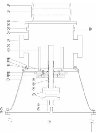
Lower plate of spark gap is bolted on centeral electrode of capacitor via a copper cylindrical connector and upper plate of the spark gap is bolted beneath the 22 cm length, 21mm diameter copper rod. The anode of focus tube is a part of this rod. Earth electrodes of capacitor (16 electrodes) are connected at the edge of cathode plate symmetrically by 16 copper strap, giving a low inductance. The pyrex insulator (fig. 2 no.8) plays an important role in the symmetrical for-mation of the current sheet and has to be stuck to anode rod. Total length of insulator is 11cm and its thickness is 2mm.
This pyrex thickness can sustain transient voltage differ-ences between anode (no. 16) and cathode plate (no. 14) dur-ing plasma focus discharges. The glue should fill the space between anode and pyrex because the glue acts as a vacuum seal.
FIG. 1: Parallel-plate spark gap (A and D are brass plates of spark gap, C is trigger electrode and B is insulator).
In addition to sealing the vacuum chamber, O-ring, (fig. 2 no.9) supports the anode rod. Polyethylene disk (fig. 2 no.10) have a 45◦groove in which oring rests. This plate is bolted under the cathode plate by three bolts and presses the or-ing. Anode is regulated vertically relative to cathode plate by these three bolts. The Cathode of focus tube is formed by 12 copper rods, 11cm-length, 1cm diameter, cylindrically placed around the anode.
The plasma chamber (fig. 3) is a 34 height, 18.6 cm-diameter and 3 mm-thickness stainless steel tube. This chamber has four 16.3cm×4cmplexyglass windows for de-tecting hard x-rays and for laser diagnostic experiments. Be-sides, the chamber has four lateral NW25 port for pumping, gas loading, pressure gauging and other purposes.
Vacuum is provided by a single-stage rotary pump reach-ing an ultimate base pressure about 4×10⁻³mbar. Pressure is read by a capacitive Gauge connecting to a lateral vacuum port.
After 5 min, because of leakage and outgases from glue, vacuum grease and materials of chamber inner surfaces, pressure is reached to about 0.01 mbar. Operating at a test pressure of 1mbar the impurity in the system is about 1%. This level of vacuum proved to be sufficient for operating with good focus in various gases and good neutron yield when operated in deuterium.
The focus tube electrodes is constructed on the basis of presented values in section 2 and are shown in fig. 4.
FIG. 2: The arrangement for SBUPF1 . 1= 25-kV,8.6-µFcapacitor; 2 = capacitor Earth stud ; 3 = capacitor H.V electrode ; 4 = con-nector ; 5 = parallel plate spark gap (indicated with details in fig. 1) ; 6 = connector ; 7 = copper strap ; 8 = pyrex insulator sleeve ; 9 = O-ring seal ; 10 = polyethylene for holding the O-ring ; 11 = Rogowski coil ; 12 = steel flange ; 13 = O-ring seal ; 14 = cathode collector plate ; 15 = focus cathode (12 rods) ; 16 = focus anode ; 17 = chamber window ; 18 = focus chamber ; 19 = outlet to vacuum pump ; 20 = flange ; 21 = back flange ; 22 = the hole for setting detector and foil ; 23 = polyethylene for thermalizing the neutron ; 24 = inlet for test gas ; 25 = insulator cap of capacitor.
FIG. 4: Focus tube electrodes
To measure the current flowing into the anode , a Ro-gowski coil (fig. 2 no. 11) and RC integrator circuit with an integration time constant of 60µsdisplayed on a two channel, 60MHz, 1Gs/s digitizing oscilloscope is used.
Calibration constant for this circuit is about 37 kA/V. For displaying the time derivative of current, Rogowski coil out-put pulse is directly applied to another channel of oscillo-scope by a 1Ωattenuator.
A silver foil activation system is used to count fusion neu-trons from the plasma. This system consists of a 3mm-thick silver foil covering a thin wall Geiger tube. The assembly is placed in center of a 14 cm-diameter polyethylene cylinder so as to thermalize the fusion neutrons.
The detector is placed on the top of plasma chamber per-pendicular to the axis of focus tube (fig. 2 no. 22) and is con-nected to a counter via an inverter, counting fusion neutrons with a calibration constant of 1.6×10⁴neutrons per count in first 100-s period after each shot. The counts being taken for two 100-s period immediately after the focus is fired. Cali-bration is performed with source removal method [16] using a 5Ci Am-Be reference neutron source. In SBUPF1 we also studied the amplitude of neutron signal pulse as detected by a PMT + plastic scintillator.
4. EXPERIMENTAL RESULTS AND CONCLUSION
The system was tested between 18-25kV in various gases including argon, neon and deuterium. A series of about 1200 shots were carried out at different load pressures and the device operation was studied. The relative strength of the plasma focus action is measured by Rogowski coil. In a plasma focus device, the axial drive phase is characterized by a smooth near-sinusoidal rising current. The focus action is indicated in the current dip. Current dip is typical feature of a focus discharge where the large increase of the plasma column impedance has occurred.
In general the stronger the focus, more severely the plasma is compressed and the bigger current dip. The focus system
would be optimized if the input current passing through the electrodes is maximum. This occurs when the focusing is generated i.e. when the current sheet (plasma) formed be-tween the electrodes reaches the top of the inner electrode and is focused. Then it maximizes the magnetic induction and leads to optimum plasma focus. In other words, the plasma axial transit time is equal to the quarter time period of discharge current, and then it becomes the optimized con-dition for the PFD [17].
µ
Ω
×
time
(5-a)
time
(5-b)
Fig. 5. Typical discharge current signals of SBUPF1 in
cu
rrent (
k
A
)
curr
en
t (kA)
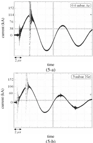
FIG. 5: Typical discharge current signals of SBUPF1 in Argon and Neon.
The system was tested at constant charging voltage 24kV. we obtained the optimum pressure for each gas by chang-ing the fillchang-ing pressure for optimum focuschang-ing condition (i.e. when the current drop occur at the quarter time period.)
Typical current waveforms at 24kV at optimum condition are shown in figure 5 For argon and Neon and in figure 6 for Deuterium. In fig. (6-b) the current derivative of fig. (6-a) has been shown.
From these experiments, it has been found that the char-acteristic current is about 115kA and the charchar-acteristic axial transit time is about 2.4µs.Characteristic current is the ampli-tude of discharge current and characteristic axial transit time refers to the time that current sheath reaches to anode top.
In argon, at 24kV, the pressure range of focusing is 0.1-1 mbar. It is observed that, as expected, the focus occurs later for higher pressures.
than argon. Focusing action was seen at pressure range of 0.2-5 mbar.
Deuterium shows the greatest range of pressure for focus-ing. Pressure range of focusing for deuterium is 2-16 mbar.
(6-a)
(6-b)
cur
rent
(
k
A
)
FIG. 6: Typical discharge current signal (a) and current derivative (b) of SBUPF1 in Deuterium.
Table 1 summarizes pressure ranges for optimum focus-ing, measured in argon, neon and deuterium.
Table 1. Measured optimum pressure ranges for various gases in SBUPF1
Gas Atomic
mass
Optimum pressure range (mbar)
Argon 40 0.3-0.5
Neon 20 1-2.5
Deuterium 2 6-10
These results show little deviation from the snow-plow model prediction.
The characteristic axial transit time, by which the current sheet approaches the top of the inner electrode for the focus-ing, is explained using the snow-plow model,
ta=
4π2(c2−1) µlnc
1/2z
0ρ 1/2 0 (I0/a)
(1)
Wheretp,a,b,µ,z0,I0 and ρ0 are axial transit time, radius of inner electrode, radius of outer electrode, permeability, length of inner electrode, characteristic current and ambient gas density, respectively andc=b/a[18].
Gas density is proportional to product of ambient gas
pres-sure and atomic mass according to ideal gas law:
ρ=P×M
R×T (2)
WhereP,M,RandTare gas pressure, atomic mass of work-ing gas, universal gas constant and temperature, respectively. Axial transit time is equal to quarter period of discharge current (2.4µsfor SBUPF1) at optimum condition.
By replacing the values in equation (1) we have
P(mbar) = 11.77
M(gr) (3)
Optimum pressure values from table 1 and the prediction by equation 3 are shown in figure 7.
For a gas with higher atomic mass, with the same charging voltage, working pressure should be less to having the same axial transit time and thus to reach the optimum condition.
FIG. 7: Variation of optimum pressure (mbar) with atomic mass of working gas
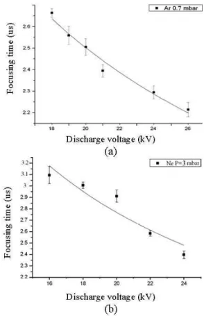
In this work, also we measured the variation of focusing time with discharge voltage at constant pressure for each gas. As expected, the focus occurs later for lower discharge volt-ages. Figure 8 shows the average dependence of the focusing time with the primary voltage of capacitor.
The system was tested in deuterium with 2.5kJ stored en-ergy at pressure range of 1-18 mbar.
Optimum pressure for maximum neutron yield is 8mbar and in this pressure, counts of 800-3000 are obtained at a 100-s period after shot. This corresponds to about 2−8×
107neutrons per shot. Figure 9 shows the variation of the neutron yield with deuterium filling pressure.
A typical oscillogram of neutron pulse is given in figure 10. neutron pulse is generated by plastic scintillator detector mounted at a distance of 4m from anode top.
4 main peaks are seen in this pulse. This is the evidence that neutron is produced at two separate phases. Time inter-val between these two phases is about 45ns.
FIG. 8: Variation of focusing time with discharge voltage in argon and neon
Pressure (mbar)
FIG. 9: Neutron yield vs. Deuterium filling pressure at 2.5kJ work-ing energy
Although only a fraction of the initial energy stored,E, in the capacitor bank is transferred to the plasma, the parame-terE/Vp∼28E/a3(with the plasma volumeVp) is usually
used to characterize the plasma energy density in order to compare different devices [8]. The energy density parameter is of the order of (1−10)×010Jm−3for a wide range of PF energies. [8]
Another relevant parameter in plasma focus is the drive
Pressure (mbar)
FIG. 10: A typical neutron pulse in SBUPF1
parameter (I0/ap1/2), whereI0is the peak current, a is the anode radius and p is the gas filling pressure for the maxi-mum neutron yield. This drive parameter (I0/ap1/2) is re-lated to the velocity of the axial and radial phases of the plasma motion (of the order of va= (0.8−1)×105 and
vr = (2−2.5)×105ms−1, respectively, for a wide range
of PF sizes). In fact, the axial and radial velocities are proportional to (I0/ap1/2). For devices in the range of 3 kJ−1 MJ operating in deuterium, the drive parameter is (I0/ap1/2) =77±7kAcm−1mbar1/2. [8]
Even though the energy density parameter is in the order of magnitude for SBUPF1 device, 5×10¹⁰J/m−3, the drive parameter gives a value of 37kA/cm.mbar1/2, this value is half of the recommended value. This is probably due to the low current limited by the high inductance of the device.
In order to optimize the device, it could be usefull to pro-duce a coaxial geometry for copper traps (fig. 2 No. 7) and spark gap and decrease length of them to decreasing total in-ductance. One way is replacing the traps by a copper cylinder to connects the cathode plate to cathode of capacitor.
One of the future works to increase neutron yield of SBUPF1 is determining optimum length of the insulator. Length of 4mm has been chosen from limited range of refer-ence [13]. The insulator length should be changed between 2.5mm & 4.5mm, thus the optimum length will be found. These optimizations, certainly will result to higher neutron yield.
In structure of SBUPF1, less number of components and less connections are used compared with conventional configuration of PF devices. Moreover, neutron yield of SBUPF1 is almost equal to yield of other devices working at same range of energy. Zakaullah et. al. [12] have reported 1.3×10⁸neutrons/shot for a 2.3kJ device at optimum anode length and optimum pressure.
Shyam and Rout [19] have reported 108n/shot for a 2.2kJ plasma focus at optimum conditions.
and land mine detection.. SBUPF1 is designed and con-structed to be used at research in the field of radiation
appli-cations such as non-destructive testing and material inspec-tion.
[1] J.W. Mather, Phys. Fluids, vol.8(2), 366 (1965).
[2] Filippov N. Filipova T. and Vinogradov V. : N. Fusion Suppl. Pt.2, 577 (1962).
[3] Lee et. al. Am. J. Phys.56(1) (1988).
[4] L. Soto et al, Physics of Plasma8, 2572 (2001). [5] P. Silva et al, Rev. Sci. Instrum.73, 2583 (2002). [6] P. Silva et al. App. Phys. Lett.83, 3269 (2003).
[7] P. Silva et al. Plasma Sources: Sci. And Technol. 13, 329 (2004).
[8] L. Soto, Plasma Physics and Controlled Fusion 47, A361 (2005).
[9] L. Soto et al, J. Phys. D: App. Phys.41, 205215 (2008). [10] R. K. Rout et al, J. Phys. D: Appl. Phys.41, 205211 (2008). [11] R. Verma et al, Plasma Sources Sci. Technol. 17, 045020
(2008).
[12] M. Zakaullah , G. Murtaza, I. Ahmad, F. N. Beg, M. M. Beg
and M. shabbir Plasma Sources Sci. and Technol.4117-124 (1995).
[13] H. R. Yousefi et al., Physics LettersA 361360-363 (2007). [14] S. Lee, in Laser and Plasma Technology, edited by S. Lee,
B. C. Tan, C. S. Wong, and A. C. Chew (World Scientific, Singapore, 1985), pp. 37, 64, and 387.
[15] S. Lee, in Radiation in Plasma,edited by B. Namara (World Scientific, Singapore, 1984), Vol. 11, p. 978.
[16] A.Gentilini et al Nucl. Instr. and Meth.172, 541-552 (1980). [17] H. J. Woo, et. al. Plasma Phys. Control. Fusion46, 1095-1104
(2004).
[18] S. Lee and A. Serban, IEEE trans. on plasma sci.24, 1101 (1996).