Abstract—A digital signature is an important public-key primitive that performs the function of conventional handwritten signatures for entity authentication, data integrity, and non-repudiation, especially within the electronic commerce environment. Currently, most conventional digital signature schemes are based on mathematical hard problems. These mathematical algorithms require computers to perform the heavy and complex computations to generate and verify the keys and signatures. In 1995, Naor and Shamir proposed a visual cryptography (VC) for binary images. VC has high security and requires simple computations. The purpose of this paper is to provide an alternative to the current digital signature technology. In this paper, we introduce a new digital signature scheme based on the concept of a non-expansion visual cryptography. A visual digital signature scheme is a method to enable visual verification of the authenticity of an image in an insecure environment without the need to perform any complex computations. Our proposed scheme generates visual shares and manipulates them using the simple Boolean operations OR rather than generating and computing large and long random integer values as in the conventional digital signature schemes currently in use.
Index Terms—Digital signature scheme, Visual cryptography, RSA signature, DSA signature, Boolean OR operation.
I. INTRODUCTION
ITH the rapid development of the Internet and the rise of E-business and E-commerce, data confidentiality, authenticity, integrity, and non-repudiation are basic concerns regarding data exchanged over an open network. A digital signature (DS) can provide the function of a conventional handwritten signature for the goals of entity authentication, data integrity, and non-repudiation [1]–[7]. DS is an important method in public-key (asymmetric) cryptography. In 1976, Diffie and Hellman [8] first introduced the concept of digital signature, which is a verification scheme that concentrates on data authenticity [9], [10]. Most current digital signature schemes are based on mathematical algorithms that require very complex mathematical computations [10]–[12]. Therefore, the sender (signer) has to depend on a computer to digitally sign a document. Also, the receiver (verifier) has to use a computer to check the validity of the signature [11]. Until now, building a digital signature scheme with high security and
Manuscript received June 14, 2010; revised October 5, 2010. This work was supported in part by a short-term grant from Universiti Sains Malaysia under the project 304/Pkomp/6310017.
Abdullah M. Jaafar and Azman Samsudin are with the School of Computer Sciences, Universiti Sains Malaysia (USM), 11800 Penang, Malaysia (Phone No.: +604-6533635; Fax: +604-6573335; Email: [email protected], [email protected]).
without complex mathematical computations has been a great challenge.
In 1997, Naor and Pinkas [13] suggested new methods for visual authentication and identification of electronic payments based on visual cryptography (VC) [14]. VC is a completely secure cryptographic paradigm that depends on the pixel level [15], [16]. It is an intuitive, easy-to-use method for encrypting private data such as handwritten notes, pictures, graphical images, and printed text after changing it to an image. VC uses the human visual system to decrypt the secret image from some overlapping encrypted images (referred to as shares printed on transparencies) without any complex decryption algorithms or the aid of computers. Hence, it can be used by anyone with or without knowledge of cryptography and without performing any cryptographic computations [14]–[28].
We therefore propose a new approach to digital signatures that is based on a non-expansion visual cryptography to overcome the disadvantage of the complicated computations required in current digital signature schemes. To achieve this, the paper is organized into the following sections. In section II, we describe conventional digital signature schemes. Section III provides background in visual cryptography. In Section IV, we explain our new proposed signature scheme. Section V presents the security analysis and time complexity of our proposed scheme and Section IV is the conclusion.
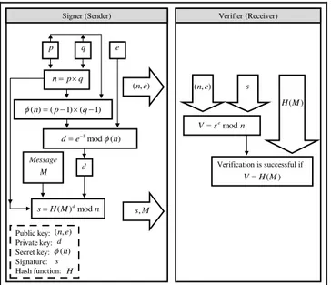
II. CONVENTIONAL DIGITAL SIGNATURE SCHEMES Digital signature (DS) is the most effective technique for ensuring authentication, integrity, and non-repudiation of data in an open network such as the Internet [1], [29], [30]. DS is a verification methodrequires the signature holder to have two keys: the private-key (signature key) for signing a message and the public-key (verification key) for verification of authenticity of the message (see Fig.1). The main goal of DS is to verify that a message has not been modified in transit after it was signed and also, to give the receiver of the message confidence that it was sent by the expected party [1], [30]–[34]. The theory of the DS algorithm was first introduced by Diffie and Hellman in 1976 [8]. However, the first practical system was the RSA digital signature scheme developed by Rivest et al. in 1978 [35]. Subsequently, DS schemes such as ElGamal signature [36], [37], undeniable signature [38] and others were proposed.
Visual Digital Signature Scheme: A New
Approach
Abdullah M. Jaafar and Azman Samsudin
Fig. 1. The digital signature scheme
Most of the current DS schemes in use are based on the difficulty to solve complex mathematical problems. The most complex mathematical problems used for designing a signature scheme are integer factorization, such as the RSA digital signature scheme, and discrete logarithms, such as the Digital Signature Algorithm (DSA) [6], [39]–[41]. In the following subsections, we explain the RSA and the DSA digital signature schemes.
A. The RSA digital signature scheme
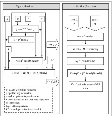
RSA in general,is a public-key algorithm that is currently being implemented worldwide for key exchange, encryption, and digital signatures [30], [31], [36]. The RSA digital signature algorithm uses a private key for signing the original message and a public key for verification [39]. Fig. 2 shows the RSA digital signature scheme, in which a signed message is sent to the receiver (the verifier). On the receiver’s side, to verify the contents of the received message, the verifier computes a new value (verification
value) from the signed message and the signer’s public key.
Next, the verifier compares the verification value with the received message value. If the two values are identical, then the original message is verified and authenticated; if not, the signature is failed. The security of the RSA digital signature is based on the difficulty to compute integer factorization problem [39], [40].
Verifier (Receiver)
Verification is successful if Signer (Sender)
Public key: Private key: Secret key: Signature: Hash function:
Message
p q e
d q p n
) 1 ( ) 1 ( )
(n p q
) ( mod
1 n
e d
) , (ne
n M H s ( )dmod
M s,
M
) , (ne
d
) (n
s
) ,
(ne s
n s V e
mod
) (M H V
) (M H
H
Fig. 2. RSA digital signature scheme
Typically, the RSA digital signature algorithm consists of three phases, as follows:
A key generation phase: In this phase, the signer (the sender) generates the private signature key, d, and a corresponding public verification key (n, e). The details of this phase for the signer are as follows:
1. Generates randomly, two large prime numbers (p, q) which are secret and of about the same size.
2. Computes , where n is the modulus and posts it publicly.
3. Computes .
4. Choose a random integer number (e), such that
and .
5. Computes the private signature key (d), such that .
6. Sends the public verification key (n, e) to a verifier (receiver).
A signing phase: In this phase, the signer inputs a message (M) and his or her private key (d), to make an output of a digital signature (s). The details of this phase for the signer (sender) are as follows:
1. Selects the message (M) to be signed and applies hash function to it, H(M).
2. Signs the message (M) with (s) as follows,
.
3. Sends the signature (s) with the message (M) to the verifier (receiver).
The digital signature verifying phase: In this phase, for a given message (M), a signer’s public key (n, e) and a digital signature (s), a verifier (receiver) decide whether to accept or reject the signature. The details of this phase for the verifier (receiver) are as follows:
1. Obtains the public key (n, e).
2. Receives the message (M) and its signature (s) from the signer.
3. Applies the hash function to the received message H(M).
4. Computes .
5. Verifies that if not, then rejects the signature or if yes, then accepts the signature.
B. The DSA digital signature scheme
In 1991, the digital signature algorithm (DSA) was proposed by the U.S. National Institute of Standards and Technology (NIST) and became a United States Government Federal Information Processing Standard (FIPS) called the Digital Signature Standard (DSS) [33]. Fig. 3 shows the digital signature algorithm (DSA), which is based on the ElGamal and Schnorr signature schemes. Both of these signature schemes are based on the same complex mathematical problem, namely, the discrete logarithms problem [1], [10], [41]. The security of DSA is based on the complexity of the discrete logarithm problem in the field of Zp, where p is a prime [40].
Message: M. Signature: S.
Signer (Sender)
To verifier Signature
algorithm S
Signed message
M
S
Signature keys
M
Verification algorithm
Accept or Reject
S
Signed message
M
Verifier (Receiver)
p, q, and g: public numbers.
y: public key of sender.
xand h: private keys of sender.
k: secret number for only one signature.
M: message. (r, s) : the signature.
k-1
: a multiplicative inverse of k. Signer (Sender)
Verification is successful if Verifier (Receiver)
x h p q
p h g p q
mod / ) 1 (
p g y x
mod
k
M
q p g
r k
mod ) mod (
q r x M H k
s( -1 ( ) )mod
M s r,), (
y g q p, , ,
M s r,), (
q s w -1mod
q w M H u1=( ( )× )mod
q w r u2=(× )mod
q p y g
v u u
mod ) mod ) (( 1 2
r v=
y g q p, , ,
Fig. 3. DSA digital signature scheme
Typically, the DSA consists of three phases, as follows:
A key generation phase: This phase is generated by a signer (sender). The details of this phase are as follows:
1. Selects a prime number (p), where for .
2. Selects a prime number (q), where q is a divisor of , and . 3. Computes where h is any
integer with such that . 4. Chooses a random integer x, with . 5. Computes .
A signing phase: This phase is generated by a signer (sender). The details of this phase are as follows:
1. Selects the message (M) to be signed and apply SHA-1 hash function to hash the message, H(M).
2. Generates a random integer (k), with ; where k must be changed for each signature. 3. Computes .
4. Computes (s) as follows:
where is a multiplicative inverse of k in .
5. Sends the signature (r, s) and the message (M) to the verifier (receiver).
A verification phase: This phase is generated by a verifier (receiver). The details of this phase are as follows:
1. Obtains .
2. Receives the message (M)and its signature (r, s) from the signer.
3. Computes .
4. Computes , where H(M) is a hash of M using SHA-1.
5. Computes .
6. Computes . 7. If , then the signature is verified;
otherwise, the signature is not verified.
III. VISUAL CRYPTOGRAPHY
Visual cryptography (VC) is a powerful technique for sharing and encrypting images. Its value is that it is easily decoded visually by humans without knowing cryptography and cryptographic computations [14], [42]–[45]. In other words, visual cryptography is a concept that does not need any computational device to decrypt an encoded image [44], [45]. The simplest model of visual cryptography is called
Naor and Shamir’s (2, 2) visual cryptography scheme,
which assumes that the original secret image is encrypted into two shadow images called transparent shares. Each pixel in the original secret image is encoded into 4 subpixels on every shadow image (transparent share) as shown in Table I. The original secret image can be decrypted by the human visual system when these two transparent shares are stacked together and the subpixels carefully aligned, where each share of these two shares looks like noise when inspected individually and reveals no information about the original secret image [13], [15], [42], [43], [46]. Fig 4
shows an example of implementing Naor and Shamir’s (2,
2) scheme.
TABLEI
NAOR AND SHAMIR’S (2,2) VISUAL CRYPTOGRAPHY SCHEME OF BLACK AND WHITE PIXELS WITH FOUR SUBPIXELS (ADAPTED FROM [14],[18],[21])
Pixel of the secret image White pixel Black pixel
Share 1
Share 2
Stacked results (Share 1+ Share 2)
Decode
Secret image
Stacking result Encode
Share 1
Share 2
Fig. 4. Demonstration of Naor and Shamir’s (2, 2) visual cryptography scheme with four subpixels (adapted from [43], [46])
Most visual cryptography methods are based on the
the problems resulting from the pixel expansion, Yang [48] proposed a new visual cryptography method without pixel expansion for various cases such as (2, 2), (2, n), (k, k), and the general (k, n) schemes. He used the abbreviation ProbVSS (Probabilistic Visual Secret Sharing) to denote his method. In this method, a black and white secret image is encrypted into the same size shares as the secret image. In other words, instead of expanding the pixel into m subpixels as used in most visual cryptography methods, Yang’s visual cryptography method uses one pixel to represent one pixel. That is, the size of the original image and shares (shadow images) are the same. Each pixel in the original secret image is represented as a black or white pixel in the shadow images without pixel expansion and the original secret image can be recovered by stacking and aligning carefully the pixels of these shares. ProbVSS method uses the frequency of white pixels in the black and white areas of the recovered image to let human visual system recognizes between black and white pixels. Also, this method uses the
term “probabilistic” point out that our eyes can recognize the contrast of the recovered image based on the differences of frequency of white color in black and white areas. The contrast of this method is defined as , where
are the appearance probabilities of white pixel in the white and black areas of recovered image. Table II
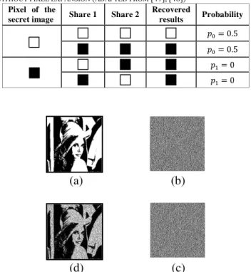
shows Yang’s (2, 2) ProbVSS scheme that a pixel on a black and white secret image is mapped into a corresponding pixel in each of the two shares. The secret image is recovered by stacking and aligning carefully the pixels of the two shares, where every pixel in share 1 is superimposed on the corresponding pixel in share 2; this is performed through the OR operation on the two transparent shares. Fig 5 shows an
example of implementing Yang’s (2, 2) ProbVSS scheme. TABLEII
THE (2,2) VISUAL CRYPTOGRAPHY SCHEME OF BLACK AND WHITE PIXELS WITHOUT PIXEL EXPANSION (ADAPTED FROM [47],[48])
Pixel of the
secret image Share 1 Share 2
Recovered
results Probability
(a) (b)
(d) (c)
Fig. 5. The (2, 2) ProbVSS scheme: (a) The secret image, (b)The first share, (c) The second share, (d) The recovered image by stacking shares (b) and (c)
IV. THE PROPOSED SCHEME
In this section we propose a new approach to the digital signature scheme based on a non-expansion visual cryptography. In addition, the proposed scheme can work with or without the aid of computing devices. Boolean operation OR is used in the generation of our proposed scheme. The OR Boolean operation works for binary inputs as follows:
The OR operation of two matrices, and , can be described by the following formulas:
The expression means that the ij-th element,
of matrix is equal to , where and are the ij-th elements of matrix and matrix , respectively.
We begin our proposed scheme by discussing the notations used. Next, we explain the new digital signature scheme, which consists of three phases: initialization phase, signature phase, and verification phase.
A. The notations
Table III summarizes notations used in this paper. TABLEIII
THE NOTATIONS
Notation Description
G An integer number with
PU A visual public share (common shadow image)
IM A black and white secret image intended to be signed
PRsi The signer’s visual private keys, where
PRvi The verifier’s visual private keys, where
PUv A verifier’s visual public key
(R, S) A visual signature pair generated by the signer
R The first visual signature share of the visual signature pair
(R, S) generated by the signer
S The second visual signature share of the visual signature
pair (R, S) generated by the signer
Csi
The first intermediate shares in the signature phase for generating the first visual signature share, R, of the visual signature pair (R, S), where
Cvi
The first intermediate shares for generating the verifier’s visual public key, PUv, where
Dsj
The second intermediate shares in the signature phase for generating the first visual signature share, R, of the visual signature pair (R, S), where
Dvj
The second intermediate shares for generating the verifier’s
visual public key, PUv, where
Esi
The first intermediate shares in the signature phase for generating the second visual signature share, S, of the visual signature pair (R, S), where
Evi The first intermediate shares in the verification phase, where
Fsj
The second intermediate shares in the signature phase for generating the second visual signature share, S, of the visual signature pair (R, S), where
Fvj The second intermediate shares in the verification phase,
where
V A visual verification share generated by the verifier A complement of the visual verification share generated by the verifier
B. Initialization phase
The proposed scheme involves two parties, the signer such as Alice and the verifier such as Bob.
Alice and Bob agree on a public integer, G, with
and a visual public share (common shadow image), PU, in the form of n×n pixels.
Alice randomly and secretly generates G+1 visual private keys (shares), denoted by PRs1,…, PRsG+1, where each one is in the form of n×n pixels.
Bob randomly and secretly generates G+1 visual private keys (shares), denoted by PRv1,…, PRvG+1, where each one is in the form of n×n pixels.
Bob generates his visual public key, PUv, as follows: First, he generates the first intermediate shares (Cv1,…, CvG) of G, as follows:
(1)
Second, he generates the second intermediate shares (Dv1,…, DvG) of G, as follows:
(2)
Third, he gets the visual public key, PUv, from the second intermediate shares (Dv1,…, DvG) of G, as
follows:
(3)
Fourth, he sends the visual public key, PUv, to Alice (the signer).
C. Signature phase
Note that, if the signer (Alice) wishes to send the image IM confidentially, she can use any existing encryption methods. To sign the image IM in the currently proposed scheme, Alice (the signer) performs the following steps:
1. She generates the first visual signature share, R, of the visual signature pair (R, S), as follows:
First, she generates the first intermediate shares (Cs1,…, CsG) of G, as follows:
(4)
Second, she generates the second intermediate shares (Ds1,…, DsG) of G, as follows:
(5)
Third, she gets the first visual signature share, R, of the visual signature pair (R, S), from the second intermediate shares (Ds1,…, DsG) of G, as follows:
(6)
2. She generates the second visual signature share, S, of the visual signature pair (R, S), as follows:
First, she generates the first intermediate shares (Es1,…, EsG) of G, as follows:
(7)
Second, she generates the second intermediate shares (Fs1,…, FsG) of G, as follows:
(8)
Third, she gets the second visual signature share, S, of the visual signature pair (R, S) from the second intermediate shares (Fs1,…, FsG) of G, as follows:
(9)
Fourth, she checks visually whether or
(full black shares); if not, proceeds to step 3; if yes; she repeats the following two steps until
and (Not full black shares).
She generates new visual private shares, PRs1,…, PRsG+1.
She performs steps 1 and 2.
3. She sends the visual signature pair (R, S) of IM to Bob (the verifier).
D. Verification phase
To verify that (R, S) is a valid visual signature of the image IM, the verifier (Bob) carries out the following steps:
1. He generates the visual verification share, V, as follows:
First, he generates the first intermediate shares (Ev1,…, EvG) of G, as follows:
(10)
Second, he generates the second intermediate shares (Fv1,…, FvG) of G, as follows:
(11)
Third, he gets the visual verification share, V, from the second intermediate shares (Fv1,…, FvG) of G, as
follows:
(12)
2. He checks whether , as follows:
First, he computes the complement of V (V is a binary
matrix “share”), denoted as , by replacing 0’s with
1’s and 1’s with 0’s.
Second, he gets the full black share, Bs, from superposition of and the signer’s second visual signature share, S, as follows:
(Full black share) (13)
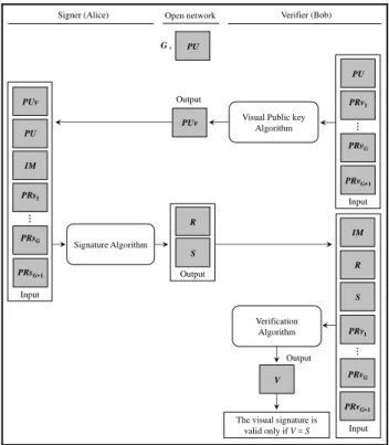
Fig. 6 shows the basic idea of the proposed scheme, namely, the Visual Digital Signature Scheme.
Input
PU PRv1
PRvG
…
Output
Visual Public key Algorithm
PUv PUv
Input
PU
PRs1
PRsG
…
IM
PRsG+1
Signature Algorithm
Output
R S
Signer (Alice) Open network Verifier (Bob)
PRv1
PRvG
…
S
Input
IM R
Verification Algorithm
V
The visual signature is valid only if V = S
PRvG+1
PU G ,
PRvG+1
Output
Fig. 6. The basic idea of the proposed scheme (Visual Digital Signature)
E. Comparison with famous current digital signature schemes
The proposed scheme has some advantages and benefits compared to conventional digital signature schemes. Table IV gives a summary of the comparison.
TABLEIV
BRIEF COMPARISON BETWEEN CURRENTLY FAMOUS DIGITAL SIGNATURE SCHEMES WITH THE PROPOSED SCHEME
Name of signature Scheme
Requirement Secret information
Security condition
Complex computation
RSA
Computers Numbers in
finite fields High High DSA
ElGamal Our
scheme Human eye
Shadow
images Average Low
Theorem 1. The verifier’s visual verification share, V, is equal to the signer’s second visual signature share, S. Proof. It is important to verify that the verifier’s visual verification share, V, and the signer’s second visual signature share, S, are the same.
The verifier’s (Bob’s) visual verification share (V):
.
Because the OR operation is distributive, we have
.
Because the OR operation is commutative and distributive, we have
.
Because the OR operation is distributive, we have
.
Because the OR operation is commutative and distributive, we have
(14)
The signer’s (Alice’s) visual signature share (S):
.
Because the OR operation is distributive, we have
.
Because the OR operation is commutative and distributive, we have
.
Because the OR operation is distributive, we have
.
Because the OR operation is commutative and distributive, we have
(15)
Because the OR operation is associative and commutative, it could be seen from Equations (14) and (15)
that the verifier’s visual verification share, V, and the
signer’s visual signature share, S, are the same, namely,
. □
V. SECURITY ANALYSIS AND TIME COMPLEXITY A. Security analysis
public key (PUv) and the visual signature pair (R, S). In addition, because the signer (Alice) has sent the secret image IM to the verifier (Bob) using one of the public-key encryption systems, an adversary will face difficulty in obtaining the IM from its encrypted image. Since Boolean OR operations are used for constructing our scheme, its security is based on the difficulty of solving random Boolean OR operations. Therefore, it is computationally infeasible to compute the visual private keys for the signer and the verifier from the visual signature pair (R, S) and the
verifier’s visual public key (PUv), especially when a large size of visual share and a large value for G are used.
B. Time complexity
The time complexity in the proposed algorithm is proportional to the visual share size and to the value of G. For the visual signature scheme, the time complexity for reconstructing a visual signature of an image, IM, is the time required to compute the visual signature pair (R, S), where the time complexity for computing the first visual signature share, R, is and the time complexity for the second visual signature share, S, is . Therefore, the sum of the time complexities of the visual signature of an image is
if the constant is neglected and also ignoring the time needed for generating 2G distinct random shares. The time complexity for reconstructing a signature verification of an image is the time required to compute the visual public key, PUv, and the visual verification share, V, where the time complexity for PUv is
and for V is . Therefore, the sum of the time complexities of the signature verification of an image is
if the constant is neglected, as well as ignoring the time needed for generating G distinct random shares. In addition, the signature phase requires
stacking (OR operations) of the visual shares. The verification phase also requires 4G stacking of the visual shares.
Supposing an attacker wants to compute the signer’s or
the verifier’s visual private keys using all information which are publicly available from our scheme (i.e., G, PU, PUv, R and S); two steps are required:
First, supposing there is no computer; Table V shows the time needed to generate and compute 2G different visual shares using the OR operations, which are used to reconstruct the visual signature pair (R, S) of an image IM, and how the time needed to compute G different visual shares, using the OR operations, used to reconstruct the visual verification share, V, performed manually (no computer). Assuming different sizes of visual shares and using the value of ; assuming also that an attacker performs one operation per minute. From the same table, it could be seen that the time required increases with increase in the size of the visual share while using . For example, the time required to reconstruct the signature phase is over one year when the visual share size is 256×256 pixels and . Similarly, the time required to reconstruct the verification phase is also over one year when the visual share size is 256×256 pixels and .
Second, supposing there is a computer; Table VI shows the time is spent to compute 2G different visual shares using
Boolean OR operations, which are used to reconstruct the visual signature pair (R, S) of an image IM, and how much time is needed to compute G different visual shares using the OR operations, which are used to reconstruct the visual verification share, V, and performed by an attacker using a computational device (i.e., a computer). Assuming the computer executes two billions instructions per second. Assume also that the use of large visual shares, as well as different and large values for G. From same table, it could be noted that the time required increases with share size or the value of G or both.
TABLEV
THE TIME SPENT FOR RECONSTRUCTING THE PROPOSED SCHEME MANUALLY
Description Visual share size (pixels)
Number of Boolean operations
Time required*
1 Signature 4×4 27 2.13 h
Verification
2 Signature 8×8 29 8.53 h
Verification
3 Signature 32×32 213 5.68 d
Verification
4 Signature 64×64 215 22.75 d
Verification
5 Signature 128×128 217 3.03 mth
Verification
6 Signature 256×256 219 1.01 yr
Verification
7 Signature 512×512 221 4.04 yr
Verification
TABLEVI
THE TIME SPENT FOR RECONSTRUCTING THE PROPOSED SCHEME BY A COMPUTER
Description Visual share size (pixels) G
Number of Boolean operations
Time required*
1
Signature
1024×1024
64 226 33 ms
512 229 268 ms
Verification 4096 2
32
2 sec
16384 234 8 sec
2
Signature
2048×2048
64 228 134 ms
512 231 1 sec
Verification 4096 2
34 8 sec
16384 236 34 sec
3
Signature
4096×4096
64 230 536 ms
512 233 4 sec
Verification 4096 2
36 34 sec
16384 238 2.29 min
4
Signature
8192×8192
64 232 2 sec
512 235 17 sec
Verification 4096 2
38
2.29 min 16384 240 9.16 min
5
Signature
16384×16384
64 234 8 sec
512 237 1.14 min
Verification 4096 2
40 9.16 min 16384 242 36.65 min
6
Signature
32768×32768
64 236 34 sec
512 239 4.58 min
Verification 4096 2
42 36.65 min 16384 244 2.44 h
7
Signature
65536×65536
64 238 2.29 min 512 241 18.32 min
Verification 4096 2
44
Note that the time shown in Table VI reflects only the execution time of Boolean operations in the scheme by a computer without taking into consideration the time needed to generate the visual private keys of the signer and the verifier. In general, these operations required manual inspection and cannot operate at high speed. Therefore, results shown in Table VI (as well as results shown in Table V) are only hypothetical assumptions based on the premise that visual comparison could be done at the rate of two billion operations per second.
VI. CONCLUSION
In this paper, a new digital signature scheme was proposed, based on a non-expansion visual cryptography concept, namely, the visual digital signature scheme. Since only the simple Boolean OR operation was used to construct the scheme rather than complex computations used in current conventional digital signature schemes, the proposed scheme is easily implemented and has a specific niche in visual applications. The security of the scheme is based on the difficulty of solving and computing random Boolean OR operations, especially when using a large portion of the visual share and a large value for G (where G must be an integer with ).
ACKNOWLEDGMENT
The authors would like to express their thanks to Universiti Sains Malaysia (USM) for supporting this study.
REFERENCES
[1] H. Zhu, D. Li, “Reseach on Digital Signature in Electronic
Commerce,” The 2008 IAENG International Conference on Internet
Computing and Web Services, Hong Kong, 2008, pp. 807–809. Available:http://www.iaeng.org/publication/IMECS2008/IMECS2008 _pp807-809.pdf
[2] N. Elfadil, “Graphical and Digital signature Combination for fulfilling
the cultural gap between traditional signature and current smart card
digital certificate/signature,” 3rd Annual Conference on Privacy,
Security and Trust, Canada, 2005.
[3] V. Liu, W. Caelli, E. Foo, “Visually sealed and digitally signed
documents,” in Proc. Of the 27th Australasian Conference on
Computer Science-Volume 26 (Dunedin, New Zealand). Estivill-Castro, Ed. ACM International Conference Proceeding Series, vol. 56. Australian Computer Society, Darlinghurst, Australia, 2004, pp. 287–294.
[4] H. Zhang, Z. Yuan, Q. Wen, “A Digital Signature Schemes Without
Using One-way Hash and Message Redundancy and Its Application
on Key Agreement,” in Proc. of the IFIP International Conference on
Network and Parallel Computing Workshops, 2007, pp. 873–878.
[5] L. Kang, X. Tang, “A New Digital Signature Scheme without One
-Way Hash Functions and Message Redundancy,” in Proc. of the
ICICS 5th International Conference on Information, Communications
and Signal, 2005.
[6] E. Ismail, N. Tahat, R. Ahmed, “A New Digital Signature Scheme
Based on Factoring and Discrete Logarithms,” Journal of
Mathematics and Statistics, vol. 4, USA, pp. 223–226, 2008.
[7] F. Yang, “Cryptanalysis on an Algorithm for Efficient Digital
Signatures,” Cryptology ePrint Archive 2005/456, 2005.
[8] W. Diffie, M. Hellman, “New Directions in Cryptography,” IEEE Transactions in Information Theory, vol. It-22, no. 6, 1976.
[9] M. Alia, “A new approach to public-key cryptosystem based on
Mandelbrot and Julia fractal sets,” Ph.D. thesis of the Universiti Sains
Malaysia (USM), 2008.
[10] W. Stallings, Cryptography and Network Security-Principles and Practices, Prentice Hall, Inc, 4th Ed., 2006.
[11] I. Fischer, T. Herfet, “Visually Authenticated Communication,” in
Proc. of the International Symposium On Systems and Information Security (SSI 2006), Brazil, 2006, pp. 471–474.
[12] B. Preneel, K. Mercierlaan, “Cryptanalysis of Message Authentication
Codes,” Department Electrical Engineering, Katholieke Universiteit
Leuven, Belgium, 2004.
[13] M. Naor, B. Pinkas, “Visual authentication and identification,” in
CRYPTO ’97: Proc. of the 17th Annual International Cryptology
Conference on Advances in Cryptology. London, UK: Springer-Verlag, 1997, pp. 322–336.
[14] M. Naor, A. Shamir, “Visual cryptography,” Advances in Cryptology
-EUROCRYPT’94, in lecture Notes in Computer Science, vol. 950,
Springer, Berlin, 1995, pp. 1–12.
[15] J. Pejaś, M. Zawalich, “Visual Cryptography Methods as a Source of
Trustworthiness for the Signature Creation and Verification Systems,”
Advances in Information Processing and Protection, Springer, USA, 2008, pp. 225–239.
[16] I. Fischer and T. Herfet, “Watermarks and Text Transformations in
Visual Document Authentication,” Journal of Computers, vol. 2, no.
5, pp. 44–53, 2007.
[17] J. Cai, “A Short Survey On Visual Cryptography Schemes,” 2004,
Available: http://www.cs.toronto.edu/~jcai/paper.pdf
[18] Y. C. Hou, “Visual cryptography for color images,” Pattern
Recognition, vol. 36, no. 7, pp. 1619–1629, 2003.
[19] R. Lukac, K. N. Plataniotis, “Bit-level based secret sharing for image
encryption,”Pattern Recognition, vol. 38, no. 5, pp. 767–772, 2005.
[20] R. Youmaran, A. Adler, A. Miri, “An Improved Visual Cryptography
Scheme for Secret Hiding,” IEEE 23rd Biennial Symposium on
Communications, 2006, pp. 340–343.
[21] C. Hsu, Y. Hou, “Visual cryptography and statistics based method for
ownership identification of digital images,” in Proc. of the
International Conference on Signal Processing (ICSP’2004), Istanbul,
Turkey, 2004, pp. 221–224.
[22] P. Tuyls, H. D. L. Hollmann, L. Tolhuizen, “XOR-based Visual
Cryptography Schemes,” Journal of Designs, Codes, and
Cryptography, vol. 37, no. 1, pp. 169–186, 2005.
[23] K. Manglem, S. Nandi, S. Birendra, L. Shyamsundar, “Stealth
Steganography in Visual Cryptography for Half Tone Images,” in
Proc. of the International Conference on Computer and Communication Engineering, Malaysia, 2008.
[24] Y. C. Hou, S. F. Tu, “A Visual Cryptographic Technique for
Chromatic Images Using Multi-pixel Encoding Method,” Journal of Research and Practice in Information Technology, vol.37, no.2, pp. 179–192, 2005.
[25] C. Lin, W. Tsai, “Visual cryptography for gray-level images by
dithering techniques,” Journal of Pattern Recognition Lett., vol. 24, no. 1-3, pp. 349–358, 2003.
[26] E. Biham, A. Itzkovitz, “Visual Cryptography with Polarization,”
Technion Israel Institute of Technology, 2004.
[27] C. Tsai, C. Chang, “A New Repeating Color Watermarking Scheme
Based on Human Visual Model,” Journal on Applied Signal
Processing, vol. 13, pp. 1965–1972, 2004.
[28] M. Nakajima, Y. Yamaguchi, “Extended Visual Cryptography for
Natural Images,” Journal of WSCG, vol.10, no. 2, 303–310, 2002.
[29] H. El-Bolok, T. A. El-Mageed, N. A. El-Salam, I. A. Elgtawal,
“Public Key Cryptosystems and its Applications in Digital Signature,”
Helwan University, Faculty of Engineering, 2003.
[30] W. Ford, Computer Communications Security: Principles, Standard Protocols and techniques, PTR Prentice Hall, 1994.
[31] A. Menzes, P. Van Oorschot, S. Vanstone, Handbook of Applied Cryptography. CRC Press, 1996, pp. 425–488.
[32] N. Carruthers, “Digital Signature Schemes,” B.Sc. thesis, Middlebury
College, 1997.
[33] C. Furlani, “Digital Signature Standard (DSS),” Federal Information
Processing Standards Publication 186-3, Information Technology Laboratory, National Institute of Standards and Technology, Fips Pub 186-3, 2008.
[34] M. Mogollon, “Cryptography and Security Services: Mechanisms and
Applications,” University of Dallas, USA, 2007.
[35] R. Rivest, A. Shamir, and L. Adleman, “A Method for Obtaining
Digital Signatures and Public-Key Cryptosystems,” Communications of the ACM, vol. 21, no. 2, pp. 120–126, 1978.
[36] C. S. Laih, K. Y. Chen, “Generating visible RSA public keys for
PKI,” Int. J. Secur., vol. 2, no. 2, Springer, Berlin, 2004, pp. 103–109.
[37] T. ElGamal, “A public key cryptosystem and a signature scheme
based on discrete logarithms,” IEEE Trans. Inform. Theory IT, vol. 31, no. 4, pp. 469–472, 1985.
[38] C. David, H. V. Antwerpen, “Undeniable Signatures,” Crypto'89,
LNCS 435, Springer-Verlag, Berlin, 1990, pp. 212–216.
[39] A. MS, “Public Key Cryptography: Applications Algorithms and
[40] M. Alia, A. Samsudin, “A New Digital Signature Scheme Based on
Mandelbrot and Julia Fractal Seta,” American Journal of Applied
Sciences, AJAS, vol. 4, no. 11, pp. 850–858, 2007.
[41] D. R. Stinson, Cryptography Theory and Practice, Chapman & Hall/CRT, 3rd Ed, 2006.
[42] J. A. Rodriguez, R. Rodriguez-Vera, “Image encryption based on phase encoding by means of a fringe pattern and computational
algorithms,” Journal of Revista Mexicana De Fisica, vol. 52, no. 1, pp. 53–63, 2006.
[43] T. Zohra, “Halftone Image Watermarking based on Visual
Cryptography,” M.S. Thesis of Electronics Science, Batna University,
Republic of Algeria, 2005.
[44] S.-F. Tu, C.-S. Hsu, “A VC-Based Copyright Protection Scheme for Digital Images of Multi-Authorship,” The 2007 International Confernce of Signal and Image Engineering, U.K., 2007, pp. 685–689 Available:http://www.iaeng.org/publication/WCE2007/WCE2007_pp 685-689.pdf
[45] C.-S. Hsu, S.-F. Tu, “Digital Watermarking Scheme with Visual
Cryptography,” The 2008 IAENG International Conference on
Imaging Engineering, Hong Kong, 2008, pp. 659–662. Available: http://www.iaeng.org/publication/IMECS2008/IMECS2008_pp659-662.pdf
[46] C. Sung, C. Lo, C. Peng, W. Tasi, “A study on VOIP Security,” Int.
Computer Symposium, Taipei, Taiwan, pp. 15–17, 2004.
[47] C.-S. Hsu, “A study of Visual Cryptography and Its Applications to
Copyright protection Based on Goal programming and Statistics,”
Ph.D. Dissertation, National Central University, Taiwan, 2004. [48] C.-N. Yang, “New visual secret sharing schemes using probabilistic
method,”Pattern Recognition Letter, vol. 25, pp. 481–494, 2004.
Abdullah M. Jaafar was born in Taiz, Republic of Yemen in March 7, 1977. He received the B.Sc. degree in Computer Science from Al-Mustansiriyah University, Baghdad, Republic of Iraq in 1999, and the M.Sc. degree in Computer Science from Iraqi Commission for Computers and Informatic, Institute for Post Graduate Studies in Informatic, Baghdad, Republic of Iraq in 2003. During 2004-2006, he worked as a lecturer at Taiz University in Republic of Yemen. Currently he is a Ph.D. student at the School of Computer Sciences, Universiti Sains Malaysia.