!
" #$ % & $ '
() *% + , -,./.0(1 . )
(2/ ) ,()2+/ 2% + 3 .4 ,(0 .
1,2
Department of Mechanical Engineering, Faculty of Engineering and Technology, University of Ilorin, Ilorin, Kwara State, Nigeria
3
College of Engineering, Department of Mechanical Engineering, Babylon University, Babylon City, Hilla, Iraq
4
Department of Mechanical Engineering, Faculty of Engineering and Technology, Ladoke Akintola University of Technology, Oyo state, Nigeria
*Corresponding Author: kadegun@unilorin.edu.ng
The paper investigated the flow of incompressible fluid and contaminant transport through a Porous Landfill using a numerical technique. A three3 dimensional finite element analysis technique was adopted for the solution. The problem was based on the Darcy’s Law and the Advection3Dispersion equation. The solutions of the Darcy’s and Advection3Dispersion equations were generated using Finite Element Analysis Software known as COMSOL Multi3 physics. This simulation tool tracked the contaminant transport in the Landfill for 360 days at 10 days interval. It first modeled steady3state fluid flow by employing the Darcy’s Law Application Mode and then followed up with a transient solute3transport simulation by employing the Solute3Transport Application Mode from the Earth Science Module of COMSOL. The solution results obtained from this model were found to be in close agreement with real3 life data obtained at the 1303 million ton Bukit Tagar Mega Sanitary Landfill site, Selangor near Kuala Lumpur, Malaysia. This showed that the model can effectively predict the trends in the distributions of pollutants from a Municipal Solid Waste Landfill into nearby land and water sources. The model is thus applicable to the issues of environmental protection and safety of groundwater.
Area, m2
Solute concentration, mg/m3 Initial solute concentration, mg/m3
Dispersion coefficients in , , directions, m2/day Permeability, m2
Discharge of fluid, that is, depth of seepage per day, m/day Darcy flux, m/day
Darcy flux at the defined boundary, m/day Time, days
Velocity of the fluid, m/s
Average fluid velocities in , , directions, m/s
, , Space coordinate
∇ Gradient operator
ϕ Piezometric head, flow potential, m Fluid absolute viscosity, N/m2s ρ Fluid density, kg/m3
The search for new techniques for the exploitation of oil reservoir by petroleum engineers, as well as recent concern with groundwater pollution problems by hydrologists has provided a great stimulus to studies of hydrodynamics in porous media. Contamination of groundwater is an issue of major concern in residential areas in the vicinity of Landfills and waste disposal repositories as municipal water supplies often depend on the utilization of the groundwater resources [133].
Phenomena of transport in porous media are encountered in many engineering disciplines such as the flow of water in aquifers, the movement of moisture through and under engineering structures, transport of pollutants in aquifers and the propagation of stresses under foundations of structures, the movement of water and solutes in the root zone in the soil, heat and mass transport in packed3 bed reactor columns and drying processes, and the flow of oil, water and gas in petroleum reservoirs [4, 5]. The theory of laminar flow through homogeneous porous media is based on a classical experiment originally performed by Henri Darcy the city engineer of Dijon [5].
A 3D Finite Element Analysis of Incompressible Fluid Flow and Contaminant .
designs using the computer code POLLUTE. Upon evaluation for the contamination of the underlying aquifer, using the drinking water standard for chlorine ion, he found out that a waste landfill design which included elements of a blanket type leachate collection layer and a compacted clay liner underneath the landfill has more certainty in controlling the contaminant transport. Mirbagheri [8] developed a mathematical and computer model for the transport and transformation of solute contaminants through a soil column from the surface to the groundwater. Wang et al. [9] proposed a numerical approach to model the flow in porous media using homogenization theory to generate a characteristic flow equation which is numerically solved using a penalty FEM schemes.
Polubarinnova [10] in his book discussed extensively theories that govern ground water while Krothe [11] studied fluid flow in porous rocks in the lemon landfill areas. A 33D study of nuclear waste contaminants flow in porous medium using finite element was carried out by Ewing et al. [12]. In his research work, he found out that gravity has significant effect on contaminant transport. The same numerical tool of finite element was adopted by Whey et al. [13] to model analytically the fluid flow and transport in unsaturated zone. The concept to the application of finite element for the purpose of solving engineering problem was presented in the book of Burnett [14]. Olaniyan et al. [15] investigated surface water contamination by the landfill seepage from Maiduguri, Yola and Kaduna, Nigeria. They used US soil conservation service model in conjunction with the Streeter3Phelps dissolved oxygen balance equation and found out that the critical dissolved oxygen concentration could be as bad as 730 to 786 mg/litre and could occur within 1.98 to 2.17 days of first contact with the steam which will begin to show sign of recovery as early as the 25th day of first contact.
The few studies in Nigeria on the effect of seepage from landfill took care of the safety of surface water, not much attention was paid to ground water safety and appropriateness of the location for digging of well in the neighborhood of such a landfill; this gap in knowledge motivated the present authors to embark on this research work with the intention of determining the location that will be safe for sinking of drinkable well /borehole in the neighborhood of landfills and to advise appropriately the concern individuals and authorities.
! "
In three dimensions, Darcy’s law can be written as:
0 2 2 2 2 2 2 = ∂ ∂ + ∂ ∂ + ∂
∂ φ φ φ
(1)
For contaminant transport in the Porous Landfill, the Advection3Dispersion equation (2) is as contained in the work of Frey et al. [16].
∂ ∂ − ∂ ∂ − ∂ ∂ − ∂ ∂ + ∂ ∂ + ∂ ∂ = ∂ ∂ 2 2 2 2 2 2 (2) The Boundary conditions are:
• The initial condition:
( , , , ) = 0at time, = 0, that is, there is no contamination initially in the soil.
• The boundary conditions:
(a)
(
, , ,)
=0 ∂∂
for = ∞, that is, the concentration gradient at a
distant boundary does not change over time.
(b)
( )
( )
( )
= + ∂ ∂ − = + ∂ ∂ − = + ∂ ∂ − , , , , ,that is, the solute is added continuously
A 3D Finite Element Analysis of Incompressible Fluid Flow and Contaminant . !
# $ "
Numerical solutions of problems in fluid dynamics are usually formulated using one of three methods: finite3volume method, finite3difference method and finite3 element method. In this work finite element was adopted because finite Element programmes such as COMSOL Multi3physics that can perform the task and that are user friendly are available commercially. The fluid flow and solute3transport equations are linked by the seepage velocity, =− ∇φ, which gives the specific flux of fluid across an infinitesimal surface representing both the solid and the pore spaces. COMSOL Multi3physics computes the Darcy velocity vector, which consists of directional velocities denoted by , and , respectively. First, it solves the Laplace equation to find the steady3state values of the hydraulic head. It then used Darcy’s law to establish the seepage velocities which were included in the time3dependent solute transport equation. The numerical solutions to the Darcy’s law and the Advection3dispersion equations were presented as generated by the Software COMSOL Multi3physics. The statistics of the mesh as generated by the software is given in Table 1.
$
$% & '
1. Number of degrees of freedom 6618
2. Number of mesh points 532
3. Number of elements 1839
4. Tetrahedral mesh 1839
5. Hexagonal mesh 0
6. Prism mesh 0
7. Number of boundary elements 814
8. Triangular mesh 814
9. Quadrilateral mesh 0
10. Number of edge elements 90
11. Number of vertex elements 12 12. Minimum element quality 0.367
13. Element volume ratio 0.041
( ) &
The results are presented for seepage velocity field(m/s), Pressure gradient(Pa/m), lechate dispersive tensor(m2/s), concentration gradient(kg/m4), concentration (kg/m3), adventive flux (kg/m2s) and dispersive flux (kg/m2s) for arc length ranging from zero to one metre(031 m).
Figure 2 shows the average transport velocity of the leachate which was calculated by dividing the Darcy flux by the effective porosity of the porous medium. It should be noted however that the actual velocity of leachate in pores within the pore spaces remain unknown as it depends on the composition and structure of the soil and also the type of voids. For the particular application of this study the peak as well as lowest values of the pressure gradient and the pressure head within the porous system should be known.
' & * +' , - .
Considering Figs. 335, it is observed that the three plots have maximum values of 3.5×10⁸ Pa/m, 4.8×1036 m/m and 1.6×1035 m/s of pressure gradient, pressure head gradient and velocity respectively at a distance of 0.1 m along the 3axis.
# $ /
A 3D Finite Element Analysis of Incompressible Fluid Flow and Contaminant . !3
( ' 0 .
1 $ ! $
.
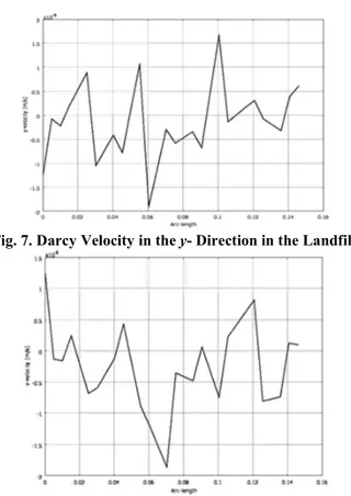
Figure 6 shows that the velocity in the x3direction is highest at 0.1 m with a value of 4.5×1036 m/s. The lowest value of 33.2×1036 m/s occurs at 0.075 m. Figure 7 predicts the velocity in the 3direction and again the highest value occurs at 0.1 m. For the velocity in the 3direction, Fig. 8 shows that the lowest value is 3 1.8×1036 m/s and occurs at 0.07 m.
3 & ' . &
4 & ' .&
Figure 9 depicts how the pollutant concentration gradients ( 3component) vary in the landfill at 10 days interval as the pollutant is continuously added at the near boundary at a constant concentration. Maximum value is 1.35×10⁷ kg/m4 at around 0.07 m at 360 days. Concentration gradients in the and 3directions fall lowest at 0.03 m and 0.07 m respectively at 360 days (Figs. 10 and 11).
5 /
A 3D Finite Element Analysis of Incompressible Fluid Flow and Contaminant . !5
6 /
.& 6 7 !
/
.& 6 7 !
Figure 12 is an isosurface of contaminant concentration within the porous medium. An isosurface plot displays a quantity as a colored set of surfaces on which the quantity has a constant value. This study shows that in a situation whereby there is constant injection of a pollutant into the landfill at a particular concentration oat source, then the pollutant concentration detectable within the
porous system will be greatest at a distance of 0.14 m along the 3plane. In this study, the peak concentration was 8.67×10⁵ kg/m3 (Fig. 12).
$ '
Figure 13 shows that the concentration gradient (total or vector sum of the three3dimensional values of concentration gradients) is lowest at the point where the concentration is highest, (at around 0.14 m along the 3axis) and that the concentration gradient is highest at between 0.06 and 0.08 m.This can also be deduced from the results depicted in Fig. 14 which is the numerical values of solute concentration at 10 days’ interval.
# $ 8 #26 &
( / 6 7 !
Figure 15 established the fact that the pressure head is highest at the base and near the center of the landfill model.
A 3D Finite Element Analysis of Incompressible Fluid Flow and Contaminant . !
1 0 & + ,
2 ! ! *
. 6 7 !
3 & ! *
. 6 7 !
• '
the present work. This validated the numerical scheme used in this research as not being far from reality and that without the expense of building an actual landfill or constructing a real porous medium, the model of this work can be applied appropriately to get the needed results.
4 & - )
9 : .$ ; $ ;
+) ' < 4=,
1
A numerical solution has been presented for the flow of an incompressible fluid and contaminant transport in an isotropic porous medium using the finite element method. The domain of solution was a scale model of a Landfill which was integrated into Finite Element analysis software COMSOL Multi3physics. By comparing real3life results obtained at the Bukit Tagar sanitary landfill shown in Figure 4.5 with the results generated using this model, as shown in Figs. 235, this work produced results that are very close to what obtains in reality.
From the results obtained, one could conclude that the model can effectively predict the trends in the distribution of pollutants from a solid waste landfill into nearby land and groundwater sources. It is also concluded that wells in the neighborhood of such solid waste landfills are better protected from contamination if sunk behind the side of the landfill where the embankment is thickest rather than in front of the landfill. It is therefore recommended to both the government and individuals that wells or boreholes in the neighborhood of solid waste landfills should be sung behind the side of the landfill where the embankment is thickest.
)
1. Verruijt, A. (1988). (2nd Ed.) University of Delft
Press, Deft.
2. Bear, J. (1987). Reidel
Publishing Co., Dordrecht.
3. The report entitled “ ! " "# #
A 3D Finite Element Analysis of Incompressible Fluid Flow and Contaminant . !
Board Committee on Groundwater Modelling Assessment to the National Academy Press, Washington D.C.
4. The United States Environmental Protection Agency, Landfills Fact Sheet, Municipal Solid Waste, available at http//www.epa.gov/epa.gov/epawaste/ nonhaz/municipal/landfill.htm. Accessed on 24th February, 2010.
5. Bear, J.: and Bachmat, Y. (1990). $ # ! "
! " ! . Reidel Publishing Co., Dordrecht.
6. Mehnert, E.; and Hensel, B.R. (1996). Coal combustion by3products associated with coal mining. $ # % & !, Southern Illinois University, Carbondale. 7. Badv, K. (2001). Evaluation of optimum landfill design by contaminant
transport analysis.$ ' (# # # , 31(5), 5353545.
8. Mirbagheri, S.A. (2004). Modelling contaminant transport in soil column and
groundwater pollution control. $ ' ) % !
(# # # , 1(2), 1413150.
9. Wang, J.G.; Leung C.F.; and Chow, Y.K. (2003). Numerical solution for
flow. In Porous Media. $ ' * ! # #
" ! # #", 27(2), 5653583.
10. Polubarinnova3Kochina, P.Y.A. (1952). ! % !
Translated from Russian by Roger De Wiest, J.M. (1962). Princeton University Press, Princeton.
11. Krothe, N.C. (2003). A study of fluid flow through porous rocks in the lemon
lane landfill area. + , ' " % ! , 50(1),
1773180.
12. Ewing, R.E.; Wang, H.; Shapley, R.C.; and Celia, M.A. (2006). A three3 dimensional finite element simulation for transport of nuclear waste contamination in porous media. ($ ' * ! # " ", 26(6), 151331524.
13. Whey, B.; Tsai, F.; Tim3Hau, L.; Ching3Jen, C.; Shin3Jye, L.; and Chia3Chen, K. (2000). Finite analytic model for low and transport in unsaturated zone.
' ) # #", 6(2), 4713479.
14. Burnett, D.S. (2009). & ! " "- & ! # # " # ". Addison3Wesley Publishing Company, Ontario.
15. Olaniyan, I.O.; Alayande. A.W.; and Bamgboye, O. (2009). Predicting surface water contamination from the Kaduna, Yola and Maiduguri landfill sites. + " # , 1(6), 63368.
16. Frey, S.; Martins3Costa, M.L.; and Saldanha Da Gama, R.M. (2008). Petrov3 Garlerkin approximation for advective3diffusive heat transfer in saturated porous media. . ! # + " # , 38(6), 1693178.
17. Scheidegger, A.E. (1972). " #" " ! (3rd
Ed.). University of Toronto Press, Toronto.
18. Kortegast, A.P.; Eldridge, S.F.; Richards, B.A.; Young, S.; Chock, E.T.; Bryce, A.; Robinson, H.; and Carville, M. (2007). Leachate generation and treatment at the Bukit Tagar landfill, Malaysia. / # " 00


![Figure 18 is a graphical representation of the actual data collected at the Bukit Tagar landfill in Malaysia [18], the trend of the behaviour of the daily leachate flow resembles the sinusoidal or saw3toothed nature of the graph](https://thumb-eu.123doks.com/thumbv2/123dok_br/18393430.357826/11.918.250.554.98.249/graphical-representation-collected-landfill-malaysia-behaviour-resembles-sinusoidal.webp)
