Journal of Applied Fluid Mechanics, Vol. 10, No. 1, pp. 319-328, 2017. Available online at www.jafmonline.net, ISSN 1735-3572, EISSN 1735-3645.
Two-Dimensional Transient Modeling of Energy and
Mass Transfer in Porous Building Components using
COMSOL Multiphysics
M. Maliki
†, N. Laredj, K. Bendani and H. Missoum
LCTPE Laboratory, Faculty of Science and Technology, University Abdelhamid Ibn Badis, Mostaganem, Algeria
†Corresponding Author Email: [email protected] (Received May 1, 2016; accepted August 6, 2016)
A
BSTRACTThis paper reports on a transient heat, air and moisture transfer (HAM) model. The governing partial-differential equations are simultaneously solved for temperature and capillary pressure through multi-layered porous media, including the non-linear transfer and storage properties of materials. Using partial differential equations functions, some thermo-physical properties of porous media are converted into coefficients depending on temperature and capillary pressure. Major features of the model are multi-dimensional and transient coupling of heat, air and moisture transport. The coupled equations are solved using the COMSOL Multiphysics time-dependent solver. This solver enables HAM (Heat, Air, Moisture) modeling in porous media. Besides, the good agreements obtained with a 2D benchmark suggest that the model can be used to assess the hygrothermal performance of building envelope components. This paper concludes that the total heat flux in the insulated wall represents only the quarter of that crossing the uninsulated concrete roof. On the other hand, the concrete having the lowest water vapour permeability of all used materials allows maintaining the vapour pressure levels close to the initial value (103 Pa). This induces a situation of interstitial condensation within the concrete of the roof. Being able to evaluate the hygrothermal behaviour, the proposed model may turn out to be a valuable tool to solve other building problems.
Keywords: Numerical modeling; Moisture; Heat; Porous media; Capillary pressure.
N
OMENCLATUREcp,m dry specific heat of material
cp,a specific heat of dry air
cp,l specific heat of liquid water
g moisture flow
ka air permeability of material
Kl liquid water permeability
LV latent heat of vaporisation
M total moisture weight pa dry air pressure
pv partial water vapour pressure
PC capillary pressure
Psat saturated water vapour pressure
Patm atmospheric pressure
q heat flux
RV gas constant for water vapour
t time
T temperature v air velocity w moisture content
heat transfer coefficient
P
vapour transfer coefficient
P
water vapour permeability
thermal conductivity
relative humiditya
air dynamic viscosity moisture storage capacity
m
dry density of the material
a
dry air densityl
water density
v
water vapour densitySubscripts
a air
cond conduction conv convection dry dry condition
e exterior side of building envelope eq equivalent
evap evaporation
g gaseous
i interior side of building envelope
l liquid
m medium
sat saturation state
surf surface
v vapour
wdr wind-driven rain
1. I
NTRODUCTIONHAM (Heat, Air, and Moisture) models are frequently being used to solve the combined transport of heat and moisture in building components. Nowadays, a wide variety of modelling tools are available. The state of the art and the different simulation programs for heat and mass transfers in buildings have been carried out by Woloszyn and Rode (2008). In addition, an overview of different approaches to modeling heat and moisture transfer was conducted by Woloszyn et al. (2009). Besides, coupled heat and moisture simulation in air-conditioned buildings and its impact on energy demands has been presented by Qin et al. (2009) and comparison between CFD and well-mixed zonal models was performed by Steeman et al. (2009). Currently, substantial published simulation programs and codes are available on moisture transfer in buildings, building materials and components, and allow the prediction of the indoor thermal environment (Korjenic and Bednar 2012; Langmans et al. 2012).
Similarly, there are valuable basic models for the simulation of coupled transport of heat and moisture providing a valid method where possible processes associated with damage in materials and construction elements can be predicted (van Schijndel 2007a, 2007b). In this way, Qinru et al. (2009) developed a numerical tool to predict combined heat, air and moisture transport in building envelopes, abbreviated as HAM-BE, by making use of commercial finite-element software, COMSOL Multiphysics is also used in the present work. The material properties being expressed as analytical or interpolation functions of moisture state variables. The convective air transport may play an important role on the prediction of both temperature and moisture content distribution within porous building envelopes (dos Santos and Mendes (2009). The dominant effect of the convective vapour flow has also been noticed.
More recently, Liu et al. (2013) evaluated the internal surface temperature of walls made of different materials. They concluded that when the moisture transfer is taken into account, the internal surface temperature has a cooling effect on the indoor air and is beneficial to improve the indoor thermal environment during the working hours in summer. Qin et al. (2009, 2010) proposed both one-dimensional and two-one-dimensional numerical solutions based on the control volume finite difference technique with fully implicit scheme in time. In their work, they adopted the vapour content and temperature as main driving potentials. Assessment of the risk of moisture related damage in valuable objects for cases with large temperature or humidity gradients in the air is described by coupling a model for heat and moisture transport in porous
materials to a commercial Computational Fluid Dynamics (CFD) package (CEN/TC89 WG10 2007).
Litavcova et al. (2014) have derived a mathematical model describing liquid water and vapour diffusion in a wet material as two separate processes. Their results are compared with classical moisture transfer solution representing transfer of both liquid water and vapour as a single moisture variable. Janssen et al. (2007) found that the common temporal discretisation of nonlinear equations may yield conservation errors, which can be solved by starting from the mixed transfer equation form. It should be noted that the three transport phenomena (HAM) were coupled and solved simultaneously for temperature, relative humidity and pressure considered as driving potentials by Tariku et al. (2010). They leaned on the so called HAMFIT method which requires less time of implementation and provides a high degree of transparency and flexibility of modeling the coupled PDEs. Dufourestel (1992) used the vapour pressure as a potential and shows that his model is equivalent to De Vries model (De Vries 1958).
A newly-developed coupled heat and moisture model including vapour and liquid moisture transport was presented by Van Belleghem et al. (2014). It has a broader application range, as it can be used to study vapour diffusion through porous materials and capillary moisture transport. The model lends itself to study the drying phenomena of porous materials and was validated against a drying experiment in which ceramic brick is used as a porous material.
Tamene et al. (2011) studied the heat transfer in a multilayered wall exposed to variable solar flux. The developed numerical code allowed them to determine influence of the coupling between heat and mass transfer on the evolution of temperature and moisture in presence of variable solar flux and external temperature.
A recent study showing the impact of the temperature dependency of the sorption curves on the hygrothermal behavior of a hemp concrete building envelope was carried out by Tran Le et al. (2016). They concluded that taking into account the influence of temperature on the sorption curves is necessary for better prediction of the hygrothermal behavior of a hemp concrete envelope.
in Mortensen et al. (2007) and Defraeye et al. (2012). Defraeye applied an external coupling procedure and used a separate CFD and HAM model which were then combined by transferring and setting the boundary conditions from one model to the other. These recent attempts to combine existing HAM models with CFD showed to be promising. They allow a more detailed and accurate modelling of the influence of convection on the heat and moisture transport in porous materials. However, the development of these hygrothermal models is still ongoing.
The current article presents a modelling and a simulation approach that tries to bridge the accuracy requirements with acceptable solver performance. The major aim of the method described in this paper is to present an accurate scheme with an acceptable simulation time that can be used to evaluate the hygrothermal performance of building components. A steady state air mass balance equation is solved together with a transient energy and moisture balance equation. The calculation domain consists of porous materials in which air transport is treated as Darcy flow.
The governing partial-differential equations (PDEs) of the three transport phenomena are coupled and solved simultaneously for temperature and capillary pressure. The model accommodates non-linear transfer and storage properties of materials, moisture transfer by vapour diffusion, capillary liquid water transport and convective heat and moisture transfer through multi-layered porous media. The PDEs are derived in such a way that each PDE is described with a single driving potential, which is continuous across the interfaces of adjoining materials. The three-coupled transient HAM equations were simultaneously solved using the COMSOL Multiphysics time-dependent solver. The solver is based on an explicit scheme with variable time stepping. The user can predefine the maximum time step so that it matches with the boundary conditions change periods.
2. DEVELOPMENT
OF
GOVERNING
EQUATIONS
Simultaneous heat and moisture transfer in a porous material involves complex physical phenomena. The strength of this complexity depends on how the mutual effect of heat on mass transfer is dealt with. Physical models that form the basis for various software tools used to predict the heat, air and moisture response of building envelopes seem quite diverse. In the coupled transfer, the moisture transport in building materials appears under two different phases: liquid and vapour. The vapour phase is split into diffusion and convection parts. Indeed, the diffusive flow of vapour is engendered by vapour pressure gradient and the corresponding conductivity represents the permeability of the vapour. As for, the convective vapour flow, it is advected by the moving air (Steeman et al. 2009). The modeling of the transfer in the vapour phase by the gradient of capillary pressure as conductive potential is the most appropriate approach and the
most used one in this kind of modeling (Carmeliet et al. 2004). For the liquid flow, moisture content gradient has been used as the driving potential in some hygrothermal tools, and moisture diffusivity was used as the moisture transfer conductivity. According to the principle of the preservation of the combined transport of heat and humidity of a representative elementary volume, which is defined as being large enough when compared to pore dimensions but small enough compared to the size of the sample, governing equations of the coupled transfer in building materials can be formulated. In order to simulate heat and moisture transfers in multi-layered wall, different kinds of transport equations and boundary conditions are required (Hens 2007). Hereafter, these equations are outlined according to the considered medium. These equations require dedicated boundary conditions in order to close the problem and solve the coupled equations. Note that, to characterize the humid air mixture, the assumption of ideal gas was made for dry air and water vapour.
2.1
Air Transfer
In this work, the transfer of air through a porous medium is implicitly included in the mass and energy conservation equations. The air flow ga is considered constant and moisture content independent. In the current model, the air transport is individually considered through the dry-air mass balance and the conservation equation can be expressed by Eq. (1) as:
0
a t ga
(1)
Poiseuille's law (Steeman et al., 2009) linking the pressure gradient to the flow velocity (v) of air is
given in Eq. (2):
a a
av k p (2)
Equation (3) allows calculating air flow under the following way:
a a
g
v (3)where ka(kg/m.s.Pa) is the air permeability of the material,
a
(Pa.s) is air dynamic viscosity,a
p (Pa) is the dry air pressure,
a
(kg/m3) is the dry air density.Therefore, the dry air transport given in Eq. (4) below can be written by substituting Eq. (3) in Eq. (1). This leads to the following equation:
a t v a
(4)
2.2
Moisture
Transfer
a finite element model based on the standard partial differential equations of coupled heat, air and moisture transfer in porous building materials (Hagentoft et al. 2004). Moisture transfer is split into vapour and liquid flow parts as shown in Eq. (5):
v l
gg g (5)
In Eq. (6), the liquid flux is described by Darcy's law:
l l C
g K P (6)
where
l
K (s) is the liquid water permeability and
C
P is the capillary pressure.
Note that vapour flow given in Eq. (7) is split into diffusion and convection driven parts:
v p v v
g
p
v (7)where
V
p is the partial water vapour pressure,
v
is the air velocity, and
V is the water vapour density. The mass balance is expressed in Eq. (8):0
w t .g
(8)
w (kg/m3) being the moisture content and t (s) is the time.
The moisture content is written in Eq. (9) in terms of temperature and capillary pressure derivative in the following way
C
C
w t w P P t
(9)
Relative humidity is often chosen as a flow potential, since it is continuous at the interface of layers of materials having different moisture storage properties. This potential is linked to the capillary pressure via relationship given by Eq. (10) (Kelvin’s law):
C l V
P
R T ln
(10)Where
l
is the water density andV
R is the gas constant for water vapour.
Combining the six last equations, one can express in Eq. (11) the governing moisture content equation in a porous material
C V
l C P C
C l
sat V
V
P w
K P P
P t
p p ln
T v
T T
(11)
2.3 Heat Transfer
For transient problems, in the absence of heat generation within the medium, the heat flow written in Eq. (12) consists of two parts (Eqs. 12-13), namely the conduction and convection parts, respectively.
cond conv
qq q (12)
The conductive part is given by
cond
q
T (13)where
T
(K) is the temperature and
(W/m.K) is the thermal conductivity. Equation (14) expresses the convection of sensible and latent heat part, it is given by,
conv a P a v V
q v
c T g L (14)where
V
L (J/kg) is the latent heat of vaporization,
a
(kg/m3) is the dry air density, and,
P a
c (J/kg.K) is the specific heat of dry air. Note that the specific heat capacity refers to humid air, while the second term accounts for latent heat.
Equation (15) gives the energy balance equation
, ,
.q cP m m c wP l T t
(15)
where ,
P m
c (J/kg.K) is the dry specific heat of material,
m
(kg/m3) is the dry density of the material, and ,P l
c (J/kg.K) is the specific heat of liquid water.
Equations (12) - (15) allow us writing the recovered equation (Eq. 16) for heat transfer as:
P ,m m P ,l
V P V V V a P ,a
c c w T t . T
L . p v L c T
(16)
2.4 Mathematical Modelling
This section addresses the model to be implemented for solving the coupled governing Eq. (11) and (16) which can be written in term of coefficients, and by considering temperature T as independent variable for heat transfer and capillary pressure PC as an independent variable for moisture transfer. In fact, it seems appropriate to assume that the moisture transfer is driven by gradients in capillary pressure (Tariku 2008). Thereby, this quantity can be regarded as a potential.
The capillary pressure PC given in Eq. (17) is defined as the pressure difference between the liquid and the gaseous phase:
C g l
P p p (17)
Moreover, the relationship between the partial water vapour pressure and the relative humidity can be expressed by Eq. (18) as:
V sat
p
P (18)where
is the relative humidity, andsat
P is the saturated water vapour pressure.
v v v C C
p p T T p P P
(19)
v v
v C C
T T
P P
(20)
Note that in the last equation, the time derivative of the moisture is none other than the moisture storage capacity, which is the slope of water retention curve
w / PC
.By injecting Eqs. (10) - (18) in Eqs. (19) - (20) and using Eq. (9), the governing equations (11) and (16) can be rewritten in term of PC and T gradients only, as shown in Eqs. (21) - (22):
p ,m m p ,l
V P sat
V P sat C
l V
V V V
a P ,a V C
l V T
c c w
t
L P
. L P T P
R T
L
v c L T P
T R T
(21)
C P sat
P sat l C
l V
V V
C l V
P P
. P T K P
t R T
v T P
T R T
(22)
sat sat
P = P∂ T∂ being the derivative of saturation vapour pressure.
To go further, the current model consists of converting, via MatLab, the measurable physical properties of the material such as K ,l
, P and
which depend on moisture content w into partial differential equations (PDEs), C ,C ,D ,D ,11 12 11 12 andT
C which are dependent on PC and T (Qin et al. 2010). Hence, the above expressions may be simplified under the form given in Eqs. (23) - (24) :
1111 1212
. .
T C
C
C T t C T C P
v D T D P
(23)
21 22 21 22 . . C C CP t C T C P
v D T D P
(24)
where
T
C is the specific heat of the medium defined as a function of dry air and liquid water heat capacities.
After simple rearrangements, Eqs. (23) - (24) can be rewritten under the simple matrix form given in Eq. (25):
. a
C C C
T t T T
d C
P t P P
(25)
where damping (da), diffusion (C) and convection
(β) matrices are respectively defined by Eqs. (26) - (27) - (28):
0 0
T a
C d
(26)
11 12
21 22
V P sat
V P sat
l V
P sat
P sat l
l V C C C C C L P L P R T P P K R T
(27)
11 12
21 22
, V V V
a P a V
l V V V l V D D v D D L c L
T R T
v
T R T
(28)
3. BOUNDARY
CONDITIONS
In building envelope simulation, the boundary conditions (BCs) and initial conditions (ICs), carefully selected and combined, greatly help to achieve good accuracy without resorting to the use of prohibitive computing times. In this framework, external BCs of building envelopes belong to three main groups (Künzel et Kiessel 1997; Hagentoft 2002) that are moisture saturation, constant heat and moisture flow, and heat/moisture flow through surface resistance film fixed on external surface. Equations. (29-30) given below provide the exterior boundary conditions based on Dirichlet assumptions. As for the internal surface of the wall, the temperature and pressure are maintained constant.
3.1 Moisture Boundary Conditions
Originally, the moisture supply from the environment ,
n e
g consists of two terms, namely the moisture supply due to wind-driven rain gwdr and the evaporation due to unequal vapour pressure between material and the surrounding air gevap . Moreover, this form is extended as shown in with the runoff module that uses the excess moisture to calculate the liquid film flow at the surface and the amount of runoff. This occurs whenever the moisture supply, due to the wind-driven rain (wdr), exceeds the possible amount of absorbed moisture at the material surface:
evap
n ,e P ,e v ,e surf ,e wdr runoff g
g p p g g
outdoor air, and
surf ,e
p is the water vapour pressure at the surface of the building envelope part. Noting that benchmarking of the above numerical model supposes that moisture content at surface is limited to the saturated value, and then no wind-driven rain and runoff water are considered in the calculations. Therefore, Eq. (29) reduces to the evaporation termgevap.
For the internal side of the wall, the moisture flux is obtained according to the following relationship:
n,i P ,i v ,i surf ,i
g
p p(30) where
P ,i
is the vapour transfer coefficient of the interior surface,v ,i
p is the water vapour pressure of the indoor air and
surf ,i
p is the water vapour pressure of the interior surface.
3.2 Heat Boundary Conditions
The heat flow across the exterior surface expressed in Eqs. (31) - (32) given below, includes the effects of conduction, convection, latent heat flow due to vapour transfer and sensible heat flow due to rain absorption, so radiation is not considered, except for the influence on Teq (longwave radiation)
, ,
, , , , ,
eq
n e e surf e
eq
p e V p m v e surf e wdr p l
q T T
L C T p p g c T
(31)
where
e is the convective heat transfer coefficient of the exterior surface, eqT
is the equivalent exterior temperature andsurf ,e
T is the temperature of the exterior surface.
Likewise, heat flux through internal surface of the building envelope,
n ,i
q , is given by:
n ,i i i surf ,i V p ,i v ,i surf ,i
q
TT L
p p(32) where
i
is the heat transfer coefficient of the interior surface,i
T is the temperature of the indoor air, and Tsu rf i, is the temperature of the interior surface.
4.
NUMERICAL
HANDLING
OF
THE
TWO-DIMENSIONAL
CASE
The validation process has been achieved. For this, the working of the aforementioned model equations has been recently implemented by Maliki et al. (2014, 2015) considering the 1D benchmark exercise #1. The latter arises from a series of benchmark cases from a work outcome of the EU-initiated project for standardization of heat, air and moisture calculation methods (European project known as HAMSTAD-WP2) (Hagentoft et al. 2004; Hagentoft 2002).
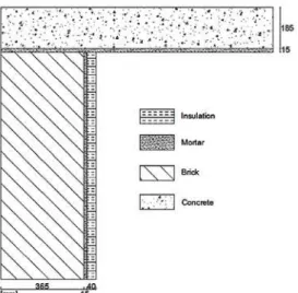
The purpose of this study is to extend the assessment of such model to two-dimensional cases. An overview of the roof structure and walls is depicted in Fig.1. Structure details for the 2D air permeable roof-wall corner are also provided. It is represented by three layers, namely mortar, brick and concrete. This is supplemented by transfer coefficients and boundary conditions.
The HAMSTAD benchmark Exercise #5 considered here deals with interstitial condensation occurring at the contact surface between two materials. This test case is challenging (Hagentoft et al. 2004) as it involves severe climatic load that causes surface condensation on the exterior surface due to nighttime cooling (low equivalent temperature), and frequent occurrences of wetting and drying of the wall due to the alternating rain and solar radiation loads.
Fig. 1. Structure details for the 2D air permeable roof-wall corner.
To complete this overview, Table 1 gathers constituent materials' properties. First though, the simulation of the benchmark exercise #1 involving condensation occurring at the contact surface between the two materials has enabled us to appraise the model's ability to correctly predict the two-dimensional case considered here. The required results are temperature field, heat flux crossing the wall from inside and water vapour pressure distribution across the computational domain.
Table 1 Properties of considered materials
Thermophysical
properties Brick MortarInsulationConcrete
dry 7.5 50 5.6 120
3
kg m
9 5 1.4 85
l
K kg msPa 7e-124.6e-11 5.5e-5 6e-11
dry W mK
0.682 0.6 0.06 1.6
3
m kg m
1600 230 212 2300
p
To undertake numerical simulation, data of the roof/wall corner, including material properties, initial condition and boundary settings, are input as constants, analytical expressions or interpolation files. This is complemented by coefficients of the conservation equation.
Needing to be able to use meshes that smoothly change in size near two different layers internal interface, where the solution is expected to change abruptly, a regular 811 mesh points has been applied producing 1496 triangular elements of normal size of only few millimeters as shown in Fig. 2.
Fig. 2. Meshing generation of the roof/wall corner.
4.1 Initial Conditions
For the whole construction, initial conditions are the following:
Relative humidity: = 60%
Temperature: T = 298 K
Water vapour pressure: Pv = 103 Pa
4.2 Boundary Conditions
For heat and moisture, a data file supplies the hourly values for a period lasting over one year. The simulation period chosen for this study case is of 20 days (480h). For intermediate values of time, they are obtained by interpolation. Fig. 3 shows the variation for a period of twenty days (simulation duration) for:
-
The outside equivalent temperatures Te encompassing both the temperatures of the ambient air and that of the radiation, Note that the internal temperature Ti is set to 20°C in order to insure optimal interior thermal comfort.- External and internal air pressure variations Peand
Pi.
The surface transfer coefficients are given by: - For heat:
2 1
, ( & )
2 1 2 1
, ( ) , ( )
25
8 ; 25
e e wall roof
e i wall e i roof
W m K
W m K W m K
- For moisture:
7 1 8 1
, 1.83 10 ; , 5.88.10
p e s m p i s m
Fig. 3. Boundary conditions for the simulation period.
4.3 Results and Discussion
4.3.1 Heat Transport
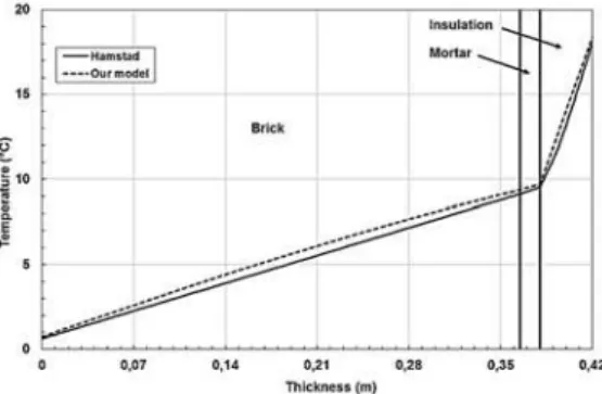
Before going further in our investigations, note first of all that we treated the heat transfer through the wall by conduction, convection and diffusion. A linear profile within the different layers is observed due to the very weak effect of the convection (no air pressure difference). In all the computations, the curves obtained are similar with those of the benchmark case as shown in Fig. 4. The highest temperature discrepancy registered is 0.5 K.
Fig. 4. Temperature profile through the wall (20 days).
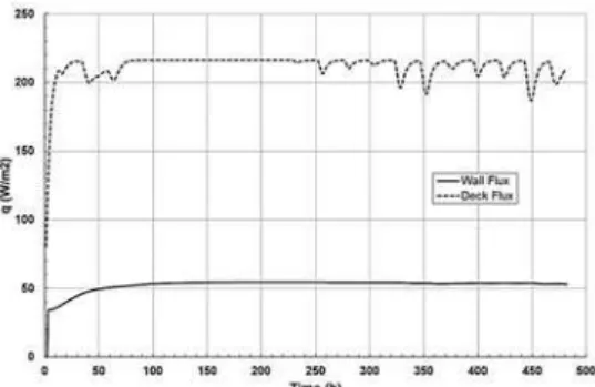
Figure 5 plots the heat flux crossing the corner from the interior for the wall and roof during the first 20 days (480 hours). It should be pointed out that after 48 hours, the curve adopts a linear behavior for the heating of the wall flow, whereas the heat flux on the roof exhibits some peaks. The graph tendency of heat flux from interior to the roof depends on the period of the day; the energy amount crossing the wall is conversely proportional to outside temperature. Indeed, an ascending tendency corresponds to the period of the day included between 3 pm and 8 am when the average temperature is globally negative with a maximum outgoing flux reached at about 8 am.
behavior during the rest of the day where the average temperature is globally positive, the lowest heat flux value is registered at 3 pm. This is understandable, in so far as the insulating material's temperature serves as a regulator helping to maintain the heat flow at a lower level. The total heat flux by conduction and convection for the wall represents the quarter of that crossing the roof.
Fig. 5. Time-dependent change of heat flux from interior to the wall and to the roof.
The insulating material facing the inner surface of the wall regulates the temperature and increase outstandingly the thermal inertia of the wall, limits considerably the heat flow dissipating towards the outside and thus energy losses as shown in Fig. 4. The roof deprived of any insulation adopts a thermal behavior opposite to that of the wall. Indeed, the distribution of the temperature is perfectly regular along the thickness of the roof, leading to a very important waste in heat flow during the simulation period; this can be easily checked by comparing the flow crossing the wall to that crossing the roof (Fig. 4). The insulating material in the wall limits the heat flow dissipating towards the outside and limits considerably energy losses as shown in Fig. 6.
Fig. 6. Temperature distribution after 480 hours.
4.3.2 Moisture Transport
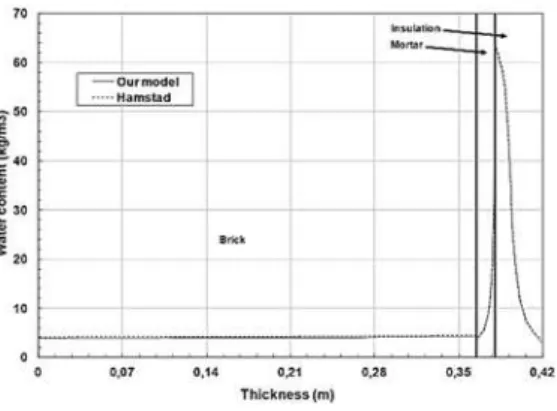
Moisture distribution was also investigated. From Fig. 7, one can observe that the calculated vapour pressure reaches very quickly the interior vapour pressure evaluated to 480 Pa. This is due to the high air permeability of the insulating layer. Also, the vapour pressure dissipating through the porous brick after 480 hours occurs in a very slow way when compared against the two other layers. On the other hand, the concrete having the lowest water vapour permeability of all used materials allows maintaining
the vapour pressure levels close to the initial value (103 Pa).
A situation of interstitial condensation is handled within the concrete of the roof. This is understandable by the very long movement of water vapour due to the low liquid diffusion coefficient of the concrete (6.10-11 Kg/(m.s.Pa) ). So it can be concluded that the concrete roof having a quasi airtight behaviour, contribute to a better maintain of the internal relative humidity essential for the users comfort.
Fig. 7. Water vapour pressure distribution after 480 hours.
The relative humidity and moisture content profiles of the wall system after 480 hours are presented in Figs. 8 and 9, respectively. As can be seen in these figures, the simulation results of the model are in very good agreement with the HAMSTAD benchmark's solutions. In the whole building hygrothermal modeling, the coupling of building enclosure and indoor environment is through interior surfaces, and therefore, it is important to accurately predict the hygrothermal states of these surfaces to obtain useful results (Tariku et al. 2004).
Fig. 8. Relative humidity evolution through the wall (after 20 days).
Fig. 9. Moisture content profile across the wall (after 20 days).
5.
C
ONCLUSIONThe present study numerically investigates the coupled heat and mass transport in porous buildings materials. The model considers the capillary pressure and the temperature gradients as driving potentials of the coupled heat and moisture transfer through porous materials of building envelope. Such a model has been successfully benchmarked against a two-dimensional numerical test case.
The governing PDEs (partial differential equations) of the three transport phenomena are coupled and solved simultaneously for potentials driving herein adopted. The model accommodates non-linear transfer and storage properties of materials, moisture transfer by vapour diffusion, capillary liquid water transport and convective heat and moisture transfer through multi-layered porous media.
The PDEs are derived in such a way that each PDE is described with a single driving potential, which is continuous across the interfaces of adjoining materials.
The COMSOL-Multiphysics solver has been chosen to solve the governing equations of HAM transport. The good agreement obtained with the considered benchmark, evidences the potential of the present model and suggests that its development and implementation are promising; thus, it can be further coupled with an indoor model to create a whole building hygrothermal model, to take into account the multi-dimensional heat, air and moisture transfer. The approach borrowed here provides a reliable and efficient model for simulating the coupled heat, air and moisture transfer through multilayer building materials.
R
EFERENCESCarmeliet, J., H. Hens, S. Roels, O. Adan, H. Brocken, R. J. Cernik, Z. Pavlik and C. Hall (2004). Determination of the liquid water diffusivity from transient moisture transfer experiments. Journal of Thermal Envelope and Building Science 27, 277-305.
CEN/TC89 WG10 (2007). Hygrothermal performance of building components and building elements - Assessment of moisture
transfer by numerical simulation (prenormative text).
COMSOL (2011). Multiphysics Modeling and Simulation Software.
De Vries, D. A. (1958). Simultaneous Transfer of Heat and Moisture in Porous Materials. Transaction of the American Geophysical Union 39, 909-916.
Defraeye, T., B. Blocken and J. Carmeliet (2012). Analysis of convective heat and mass transfer coefficients for convective drying of a porous flat plate by conjugate modelling. International Journal of Heat and Mass Transfer 55(1-3), 112-124.
dos Santos, G. H. and N. Mendes (2009). Combined Heat, Air and Moisture (HAM) Transfer Model for Porous Building Materials. Journal of Building Physics 32, 203-220.
Duforestel, T. (1992). Metrological Basics and Models for the Simulation of Hygrothermal Behavior of building components and structures. Ph. D. thesis, École Nationale des Ponts et Chaussées, France.
Hagentoft, C. E. (2002). HAMSTAD - Final report: Methodology of HAM-modeling. Rep. R-02:8. Gothenburg, Department of Building Physics, Chalmers University of Technology.
Hagentoft, C. E., A. Kalagasidis, B. Adl-Zarrabi, S. Roels, J. Carmeliet, H. Hens, J. Grunewald, M. Funk, R. Becker, D. Shamir, O. Adan, H. Brocken, K. Kumaran and R. Djebbar (2004). Assessment Method of Numerical Prediction Models for Combined Heat, Air and Moisture Transfer in Building Components: Benchmarks for One-dimensional Cases. Journal of Thermal Envelope and Building Science 27(4), 327-352. Hens, H. (2007). Building Physics-Heat, Air and
Moisture, Fundamentals and Engineering Methods with Examples and Exercises. Ernst and Sohn A Wiley Com.
Janssen, H., B. Blocken and J. Carmeliet (2007). Conservative modeling of the moisture and heat transfer in building components under atmospheric excitation. International Journal of Heat and Mass Transfer 50(5-6), 1128-1140. Korjenic, A., T. Bednar (2012). An analytical
solution of a moisture transfer problem for coupled room and building component. Energy and Building 47, 254 - 259.
Künzel, H. M. and K. Kiessel (1997). Calculation of heat and moisture transfer in exposed building components. International Journal of Heat and Mass Transfer 40(1), 159-167.
Langmans, J., A. Nicolai, R. Klein and S. Roels (2012). A quasi-steady state implementation of air convection in a transient heat and moisture building component model. Building and Environment 58, 208 - 218.
I. Sarhadov, J. Seman and T. Bednar (2014). Diffusion of moisture into building materials: A model for moisture transport. Energy and Building 68, 558-561.
Liu, Y., Y. Wang, D. Wang and J. Liu (2013). Effect of moisture transfer on internal surface temperature. Energy and Building 60, 83–91. Maliki, M., N. Laredj, H. Missoum, K. Bendani, and
N. Hassan (2015). Numerical modelling of coupled heat, air and moisture transfer in building envelopes. Mechanics and Industry 16 (5), 509.
Maliki, M., N. Laredj, K. Bendani and H. Missoum (2014). Numerical modelling of hygrothermal response in building envelopes. Građevinar 66(11), 987-995.
Mortensen, L. H., M. Woloszyn, C. Rode and R. Peuhkuri (2007). Investigation of microclimate by CFD modeling of moisture interactions between air and constructions. Journal of Building Physics 30(4), 279–315.
Qin, M., A. Aït-Mokhtar and R. Belarbi (2010). Two-dimensional hygrothermal transfer in porous building materials. Applied Thermal Engineering 30, 2555-2562.
Qin, M., R. Belarbi, A. Aït-Mokhtar and L. O. Nilsson (2009). Coupled heat and moisture transfer in multi-layer building materials. Construction Building Materials 23, 967–975. Qinru, L., R. Jiwu and F. Paul (2009). Development
of HAM tool for building envelope analysis. Building and Environment 44, 1065-1073. Steeman, H. J., A. Janssens, J. Carmeliet and M. De
Paepe (2009). Modelling indoor air and hygrothermal wall interaction in building simulation: Comparison between CFD and a well-mixed zonal model. Building and Environment 44(3), 572-583.
Steeman, H. J., M. Van Belleghem, A. Janssens and M. De Paepe (2009). Coupled simulation of heat and moisture transport in air and porous materials for the assessment of moisture related damage. Building and Environment 44(10), 2176-2184.
Tamene, Y., S. Abboudi and C. Bougriou (2011).
Study of heat and moisture diffusion through a wall exposed to solar heat flux. Journal of Engineering Science and Technology 6(4), 429-444.
Tariku, F. (2008). Whole building heat and moisture analysis. Ph. D. thesis, Concordia University, Montreal, Canada.
Tariku, F., M. K. Kumaran and P. Fazio (2010). Transient model for coupled heat, air and moisture transfer through multilayered porous media. International Journal of Heat and Mass Transfer 53, 3035-3044.
Tran Le, A. D., D. Samri, M. Rahim, O. Douzane, G. Promis, C. Maalouf, M. Lachi and T. Langlet (2016). Effect of Temperature-Dependent Sorption Characteristics on the Hygrothermal Behavior of a Hemp Concrete Building Envelope Submitted to Real Outdoor Conditions. Journal of Applied Fluid Mechanics 9(2), 245-252.
Van Belleghem, M. Steeman, H. Janssen, A. Janssens, M. De Paepe (2014). Validation of a coupled heat, vapour and liquid moisture transport model for porous materials implemented in CFD. Building and Environment 81, 340-353.
van Schijndel, A. W. M. (2007). Integrated Heat Air and Moisture Modeling and Simulation. Ph. D. thesis, Eindhoven University, Eindhoven, Netherlands.
van Schijndel, A. W. M. (2007). The effect of micro air movement on the heat and moisture characteristics of building constructions. Dissertation, Eindhoven University of Technology.
Woloszyn, M., C. Rode, A. S. Kalagasidis, A. Janssens, and M. De Paepe (2009). From EMPD to CFD - Overview of different approaches for heat air and moisture modeling in IEA annex 41. ASHRAE Transactions 115(2), 96-110.