LINEAR ELASTIC BEHAVIOUR OF
CYLINDRICAL SHELL
S. S. ANGALEKAR1*
HOD Civil Engineering Department, ATS’s SBGI, Miraj 416410, Maharashtra, India
Dr. A. B. KULKARNI2
Ex. HOD Applied Mechanics Department, WCE, Sangli 416415, Maharashtra, INDIA
Abstract.
The intensive investigation of structural behavior of cylindrical concrete shell is carried out by using finite element method of analysis. The linear elastic analysis is performed wherein concrete is assumed to be homogeneous, isotropic having linear elastic behaviour. For a fixed cross section of shell, a parametric study involving various spans and thicknesses is undertaken. Besides the self weight, loads considered are a uniform surcharge over the shell surface and longitudinal thrust. For the finite element analysis type of elements employed are 4 noded plate elements. Results of investigation are presented in the form of useful graphical representations and same are discussed. One of the interesting findings of investigation is the graphical representation of longitudinal stresses, bending moments relates to the displacement behavior of the elements used in the analysis.
Keywords: linear elastic behavior, 4 noded Kirchhoff flat plate element, surcharge, longitudinal thrust.
1. Introduction
Shells of various shapes to cover large unobstructed areas have been a focus of attention since ancient times. Particularly, thin concrete shells can cover large space and are aesthetically pleasing. Due to complex mathematical equations to define the shapes of these shells, closed formed equations are available, for simple shell forms like cylindrical shells. The analysis of shells is basically divided into two types of forces to find:
a) Membrane forces and
b) Bending forces.
The analysis of membrane forces is comparatively easy; however bending analysis becomes very complicated even for simple cylindrical shells.
Advent of finite element method has given a powerful tool to the designer for analysis and design of these complicated forms. During the complete analysis procedure, the finite element technique gives both membrane forces and bending forces simultaneously, along with displacement at various nodal positions. However, these techniques are used in the elastic range of the material.
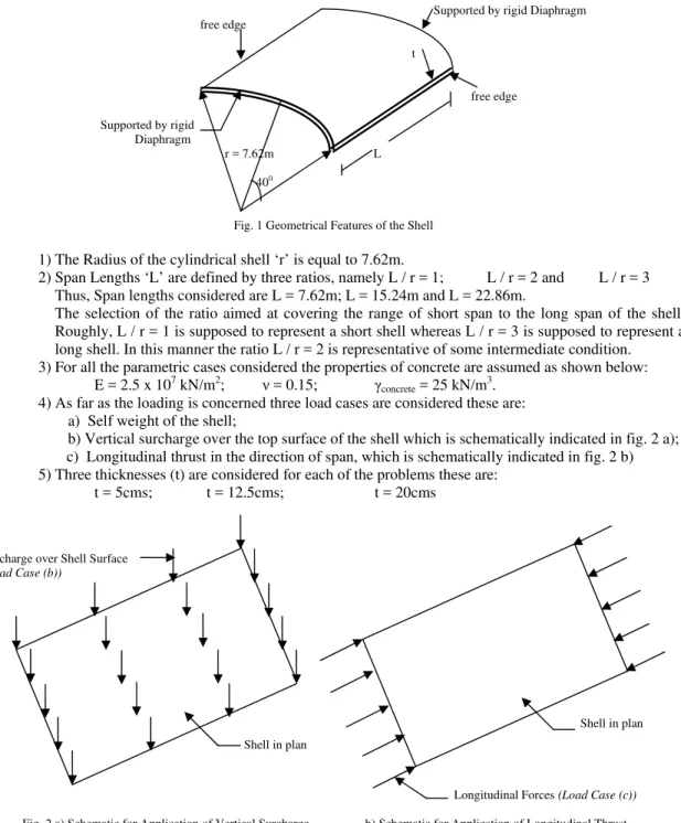
As an important component of intensive investigation of the structural behaviour of cylindrical shell, a parametric investigation is planned (Minjie C et al., 2003). For this the concrete is assumed to be homogeneous, isotropic and having linear elastic behaviour. The parameters considered are as follows: (fig.1)
For the investigation following details of the cylindrical shell are taken up:
1) Shell thickness of 12.5cms;
2) The L/r ratios of 1, 2 and 3 and
3) The Load cases pertaining to Vertical Surcharge and Longitudinal applications
For the total finite element analysis 4 noded Kirchhoff flat plate element is used.
*
Corresponding author at; (ANGALEKAR S. S.) HOD Civil Engineering Department, ATS’s SBGI, Miraj 416410, Maharashtra, India Tel.: - +91-233-2300781, Mob.: - +919422613967
Supported by rigid Diaphragm free edge
t
free edge
Supported by rigid Diaphragm
r = 7.62m L
400
Fig. 1 Geometrical Features of the Shell
1) The Radius of the cylindrical shell ‘r’ is equal to 7.62m.
2) Span Lengths ‘L’ are defined by three ratios, namely L / r = 1; L / r = 2 and L / r = 3
Thus, Span lengths considered are L = 7.62m; L = 15.24m and L = 22.86m.
The selection of the ratio aimed at covering the range of short span to the long span of the shell. Roughly, L / r = 1 is supposed to represent a short shell whereas L / r = 3 is supposed to represent a long shell. In this manner the ratio L / r = 2 is representative of some intermediate condition. 3) For all the parametric cases considered the properties of concrete are assumed as shown below:
E = 2.5 x 10⁷ kN/m2; ν = 0.15; γconcrete = 25 kN/m3.
4) As far as the loading is concerned three load cases are considered these are: a) Self weight of the shell;
b) Vertical surcharge over the top surface of the shell which is schematically indicated in fig. 2 a); c) Longitudinal thrust in the direction of span, which is schematically indicated in fig. 2 b)
5) Three thicknesses (t) are considered for each of the problems these are:
t = 5cms; t = 12.5cms; t = 20cms
Surcharge over Shell Surface
(Load Case (b))
Shell in plan
Shell in plan
Longitudinal Forces (Load Case (c))
Fig. 2 a) Schematic for Application of Vertical Surcharge b) Schematic for Application of Longitudinal Thrust
Details of these 4-noded Kirchhoff Flat plate elements characteristics are easily available in the
texts on Finite element method (Zienkiewicz O. C., 2000).
2. Finite Element Modeling
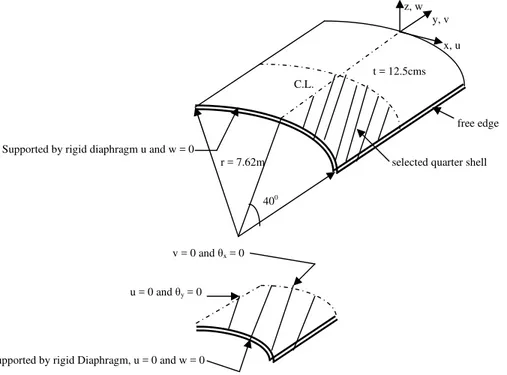
The shells under considerations have details such as reference axes, axes of symmetry and boundary conditions as shown in Fig. 3.
Due to the available axes of symmetry only one quarter of the shell is considered for the analysis(Elias Z.
z, w y, v
x, u
t = 12.5cms C.L.
free edge
Supported by rigid diaphragm u and w = 0
r = 7.62m selected quarter shell
400
v = 0 and θx = 0
u = 0 and θy = 0
Supported by rigid Diaphragm, u = 0 and w = 0
Fig. 4 Details of Axes and Boundary condition for Shell
The idealization details are presented over fig. 4 (a) i, ii, iii
16 17 18 19 20 31 32 33 34 35 46 47 48 49 50
11 12 13 14 1526 27 28 29 30 41 42 43 44 45
6 7 8 9 10 21 22 23 24 25 36 37 38 39 40
1 2 3 4 5 16 17 18 19 20 31 32 33 34 35
Fig. 5 - i L / r = 1
11 12 13 14 15 26 27 28 29 30
6 7 8 9 10 21 22 23 24 25
1 2 3 4 5 16 17 18 19 20
Fig. 5 - ii L / r = 2
11 12 13 14 15
6 7 8 9 10 Idealization Scheme of 4 noded Plate Elements used for Shell Analysis
3. Deflected Profiles
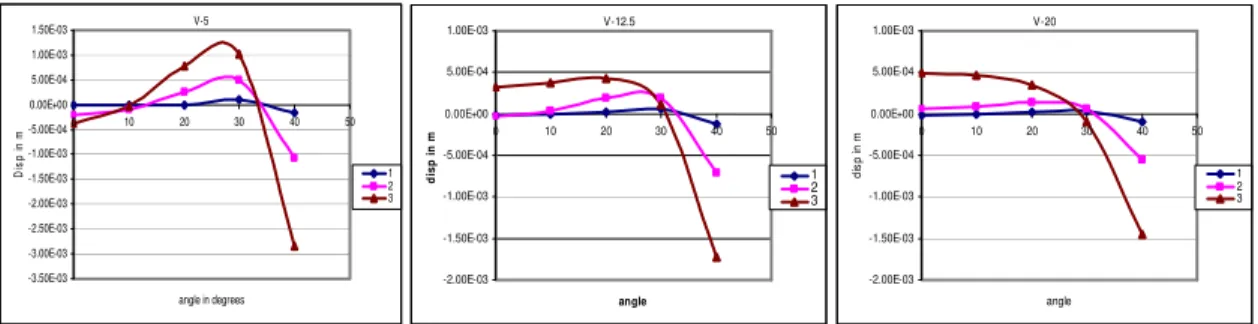
It is considered important to evaluate the vertical displacement ‘w’ at the central section of the shell whereas longitudinal displacement ‘v’ suffered at shell end support. In fact this is the manner, in which deflected profiles are presented (Zienkiwicz O. C. and Tayler R. L., 2000).
In the graphical presentation, the Y axis values indicate the values of deflections ‘v’ and ‘w’ in meters,
while on X axis values indicate positions of nodal points of cylindrical shell in degrees (θ0) for the complete set
of deflection results and for graphs of maximum values of ‘v’ and ‘w’, the X axis indicates values of L/r ratios (i.e. 1, 2, 3).
A) 4 Noded Shell Element
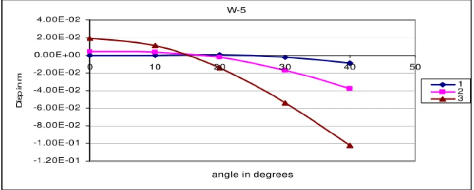
The complete set of results for the 4 noded shell elements is presented in fig. 6.1. It may be noted that both the span length and thickness of the shell are having the significant influence over the deflected profiles. The scrutiny of the results presented indicates that maximum upward deflection ‘w’ occurs at the crown of the shell whereas the maximum down ward deflection occurs at the free edge of the shell. The variations of these maximum values with respect to span and thickness are presented in fig. 7.
W-5
-1.20E-01 -1.00E-01 -8.00E-02 -6.00E-02 -4.00E-02 -2.00E-02 0.00E+00 2.00E-02 4.00E-02
0 10 20 30 40 50
angle in degrees
Di
s
p
i
n
m 1
2 3
As span ratio increases the curve for ‘w’ develops a trend of increased upward movement at the crown and the increased downward ‘w’ at the free edge. The increase between span ratio 2 and 3 as compared that between span ratio 1 and 2 is quite high. This is expected because the influence of the bending action becomes more prevalent as compared with the influence of the membrane action.
W-12.5
-3.50E-02 -3.00E-02 -2.50E-02 -2.00E-02 -1.50E-02 -1.00E-02 -5.00E-03 0.00E+00 5.00E-03
0 10 20 30 40 50
angle in degrees
Di
s
p
i
n
m 1
2 3
W-20
-1.80E-02 -1.60E-02 -1.40E-02 -1.20E-02 -1.00E-02 -8.00E-03 -6.00E-03 -4.00E-03 -2.00E-03 0.00E+00 2.00E-03
0 10 20 30 40 50
angle in degrees
di
s
p
i
n
m 1
2 3
Fig. 6 Complete Set of Results of ‘w’ for the 4 Noded Shell Element
Similar trend has been observed in case of the increased thickness of the shell from 5cms to 12.5cms and 12.5cms to 20cms.From fig. 6 it is clearly seen that for any L/r ratio as the thickness increases the vertical displacement ‘w’ gets reduced.
w @ crown
-5.00E-03 0.00E+00 5.00E-03 1.00E-02 1.50E-02 2.00E-02 2.50E-02
0 0.5 1 1.5 2 2.5 3 3.5
L/r ratio
di
s
p i
n m 5
12.5 20
w @ free edge
-1.20E-01 -1.00E-01 -8.00E-02 -6.00E-02 -4.00E-02 -2.00E-02 0.00E+00
0 0.5 1 1.5 2 2.5 3 3.5
L/r Ratio
di
s
p i
n m
5
12.5 20
i) w @ Crown ii) w @ Free Edge
Fig. 7 Variations of Maximum values of ‘w’ with respect to Span and Thickness
It is clearly seen from fig. 7 (i) and (ii) that, as the L/r ratio gets increased ‘w’ gets increased at the free
should be recognized that the maximum values occur at three different locations: I) at crown; II) at free edge and III) at some intermediate locations.
V-5 -3.50E-03 -3.00E-03 -2.50E-03 -2.00E-03 -1.50E-03 -1.00E-03 -5.00E-04 0.00E+00 5.00E-04 1.00E-03 1.50E-03
0 10 20 30 40 50
angle in degrees
Di s p in m 1 2 3 V-12.5 -2.00E-03 -1.50E-03 -1.00E-03 -5.00E-04 0.00E+00 5.00E-04 1.00E-03
0 10 20 30 40 50
angle d is p in m 1 2 3 V-20 -2.00E-03 -1.50E-03 -1.00E-03 -5.00E-04 0.00E+00 5.00E-04 1.00E-03
0 10 20 30 40 50
angle di s p i n m 1 2 3
Fig. 8 Complete Set of Results of ‘v’ for the 4 Noded Shell Element
From the above presentation it is observed that the longitudinal displacement at the crown has an inward movement for 5cms thickness and as the thickness increases it shifts towards the outward movement with maximum being for thickness 20cms.
v @ crown
-5.00E-04 -4.00E-04 -3.00E-04 -2.00E-04 -1.00E-04 0.00E+00 1.00E-04 2.00E-04 3.00E-04 4.00E-04 5.00E-04 6.00E-04
0 0.5 1 1.5 2 2.5 3 3.5
L/r Span Ratio
di s p in m 5 12.5 20
v @ free edge
-3.00E-03 -2.50E-03 -2.00E-03 -1.50E-03 -1.00E-03 -5.00E-04 0.00E+00
0 0.5 1 1.5 2 2.5 3 3.5
L/r Ratio di s p in m 5 12.5 20
v @ intermediate
-2.00E-04 0.00E+00 2.00E-04 4.00E-04 6.00E-04 8.00E-04 1.00E-03 1.20E-03
0 0.5 1 1.5 2 2.5 3 3.5
L/r Ratio di s p in m 5 12.5 20
i) v @ Crown ii) v @ Free Edge iii) v @ Intermediate
Fig. 9 Variations of Maximum values of ‘w’ with respect to Span and Thickness
The various results presented above are indicative of the behavioural changes with the range of short span and the long span. This may be witnessed from the fact that the trend of the curves change somewhere in between L/r = 2 and L/r = 3.
3. Longitudinal Stress and Bending Moments
It has been well recognized fact that the forces and moments are observed to follow the trend of the deflected patterns. For the sake of illustration, however the result derived for the 4 noded quadrilateral element are shown in fig. 10.
Values on Y axis indicate Longitudinal Stress ‘Sy’ in kN/m2 and Moments ‘Mx’ and ‘My’ in kNm.
Sy -1.50E+03 -1.00E+03 -5.00E+02 0.00E+00 5.00E+02 1.00E+03
0 10 20 30 40 50
angle in degrees
Lo ngi tu di na l S tre s s in K N /m 2 Sy1 Sy2 Sy3 Sy -8.00E+02 -6.00E+02 -4.00E+02 -2.00E+02 0.00E+00 2.00E+02 4.00E+02 6.00E+02 8.00E+02
0 10 20 30 40 50
angle in degrees
Lon gi tu di nal s tres s in K N /m 2 Sy1 Sy2 Sy3 Sy -1.00E+03 -8.00E+02 -6.00E+02 -4.00E+02 -2.00E+02 0.00E+00 2.00E+02 4.00E+02 6.00E+02 8.00E+02
0 10 20 30 40 50
angle in degrees
Lo n gi tud in al s tr es s K N /m 2 Sy1 Sy2 Sy3
(a) Thickness 5cms (b) Thickness 12.5cms (c) Thickness 20cms
Mx -2.00E-01 0.00E+00 2.00E-01 4.00E-01 6.00E-01 8.00E-01 1.00E+00 1.20E+00 1.40E+00
0 10 20 30 40 50
angle in degrees
Mx i n K N m MX1 MX2 MX3 Mx 0.00E+00 1.00E+00 2.00E+00 3.00E+00 4.00E+00 5.00E+00 6.00E+00
0 10 20 30 40 50
angle in degrees
Mx K N m MX1 MX2 MX3 Mx -2.00E+00 0.00E+00 2.00E+00 4.00E+00 6.00E+00 8.00E+00 1.00E+01
0 10 20 30 40 50
angle in degrees
Mx i n K N m MX1 MX2 MX3
(d) Thickness 5cms (e) Thickness 12.5cms (f) Thickness 20cms
Mx in Cylindrical Shell for 1, 2, 3 Ratios
My -1.00E-01 -5.00E-02 0.00E+00 5.00E-02 1.00E-01 1.50E-01 2.00E-01
0 5 10 15 20 25 30 35 40 45
angle in degrees
My K N m MY1 MY2 MY3 My -6.00E-01 -4.00E-01 -2.00E-01 0.00E+00 2.00E-01 4.00E-01 6.00E-01
0 10 20 30 40 50
angle in degrees
My in K N m MY1 MY2 MY3 My -1.00E+00 -8.00E-01 -6.00E-01 -4.00E-01 -2.00E-01 0.00E+00 2.00E-01 4.00E-01 6.00E-01
0 10 20 30 40 50
angle in degrees
My K N m MY1 MY2 MY3
(g) Thickness 5cms (h) Thickness 12.5cms (i) Thickness 20cms
My in Cylindrical Shell for 1, 2, 3 Ratios
Fig. 10 Trend of Deflected Patterns of Sy, Mx, My by 4 Noded Flat Shell Element
4. Longitudinal Membrane Stresses (Sy)
Over the transverse section of the shell the longitudinal membrane stresses indicate tensile as well as compressive characters. At free edge and at the crown they indicate tensile forces where as at the intermediate portion they indicate compressive forces. Once more the maximum at free edge and maximum at intermediate portion are plotted over fig. 11 where from the influence of span as well as thickness of the shell is clearly significant.
It may be seen at the free edge the longitudinal membrane stress, which is of tensile nature, reduces with thickness. Same is also true of the compressive membrane force at the intermediate location. The maximum value for the compressive stresses varies almost linearly with the span length.
Sy @ free edge
0.00E+00 1.00E+02 2.00E+02 3.00E+02 4.00E+02 5.00E+02 6.00E+02 7.00E+02 8.00E+02
0 0.5 1 1.5L/r ratios2 2.5 3 3.5
Sy K N /m 2 5 12.5 20
Sy @ intermediate
-1.20E+03 -1.00E+03 -8.00E+02 -6.00E+02 -4.00E+02 -2.00E+02 0.00E+00
0 0.5 1 1.5 2 2.5 3 3.5
L/r ratios S y KN/ m 2 5 12.5 20
(a) Sy @ Free Edge (b) Sy @ Intermediate
Fig. 11 Maximum Longitudinal membrane Stresses (Sy)
5. Transverse Moments (Mx) and Longitudinal Moments (My)
6. Summary and Conclusions
1) Both the span length and thickness of the shell are having the significant influence over the deflected
profiles.
2) For the same span length shell, as the thickness increases there is a decrement in the displacement profile.
3) Stress and moment profile shows a similar profile pattern as that of the displacement profiles, which clearly
indicates that the stress and moments are the relative functions of the displacements.
4) For the total scope of parametric study the overall behavioural Pattern of the displacements, stresses and
moments is same for all types of shells under consideration.
5) The selection of quarter shell considering the symmetry about both the axes shows a symmetrical result
base output, which reduces the overall front-width in the calculation of stiffness matrices in the finite element method of analysis.
7. Acknowledgement
During this work the guidance received from Mr. S. K. Parikh and also the valuable references obtained from Dr. S. N. Tande are gratefully acknowledged.
8. References
[1] Cirak F. et al. (2000): “Subdivision Surfaces: A New Paradigm For Thin-Shell Finite-Element Analysis,” California Institute of Technology, Pasadena, CA 91125, USA, pp. 110-119.
[2] Elias Z. M. (1972): “Mixed Finite Element Method for Axisymmetric Shells,” International Journal for Numerical Methods in Engineering, Vol. 4, pp. 261-277.
[3] Grafton P. E. and Strome D. R. (1963): “Analysis of Axisymmetric Shells by the Direct Stiffness Method,” AIAA Journal, Vol. 2, No.3, pp. 304-332.
[4] Minjie C et al. (2003): “Parametric Study on the Buckling of Thin Steel Cylindrical Shells under Elevated Local Axial Compression Stresses,” ASCE Journal, Vol-101, pp. 749-761.
[5] Zienkiewicz O. C. (2000): “The Finite Element Method (5th
Edition),” Vol. 2, Solid Mechanics, Butterworth Publication, pp. 61-62. [6] Zienkiwicz O. C. and Tayler R. L.(2000): “Shells as an Assembly of Flat Elements,” Finite Element Method, Vol.-2, Solid Mechanics,