American Journal of Engineering Research (AJER)
e-ISSN : 2320-0847 p-ISSN : 2320-0936
Volume-03, Issue-10, pp-188-202
www.ajer.org
Research Paper Open Access
w w w . a j e r . o r g
Page 188
Study the Effective of Shear Wall on Behavior of Beam in Frame
Structure
Dr, Hadihosseini
1, Mahdi hosseini
2, Ahmad hosseini
31,
Aerospace Engineering , working in International Earthquake Research Center of America (IERCA)
2,
Master of Technology in Structural Engineering, Dept. of Civil Engineering, Jawaharlal Nehru Technological University Hyderabad (JNTUH), Hyderabad, Telengana , India
3,
Under Graduate Student in Mechanical Engineering, Dept. of Mechanical Engineering,Kakatiya University Warangal, Telengana, India
ABSTRACT:
Shear walls are a type of structural system that provides lateral resistance to a building or structure. They resist in-plane loads that are applied along its height. The applied load is generally transferred to the wall by a diaphragm or collector or drag member. The performance of the framed buildings depends on the structural system adopted for the structure The term structural system or structural frame in structural engineering refers to load-resisting sub-system of a structure. The structural system transfers loads through interconnected structural components or members. These structural systems need to be chosen based on its height and loads and need to be carried out, etc. The selection of appropriate structural systems for building must satisfy both strength and stiffness requirements. The structural system must be adequate to resist lateral and gravity loads that cause horizontal shear deformation and overturning deformation. Other important issues that must be considered in planning the structural schemes and layouts are the requirements for architectural details, building services like vertical transportation and fire safety among others. Each of the structural system will be having its own prospects and considerations. The efficiency of a structural system is measured in terms of their ability to resist lateral load, which increases with the height of the frame. A building can be considered as tall when the effect of lateral loads is reflected in the design. Lateral deflections of framed buildings should be limited to prevent damage to both structural and nonstructural elements. In the present study, the structural performance of the framed building with shear wall will be analysis. The importance of the shear wall in resist the wind and earthquake load are study, the effect of the shear walls on the conventional frame system. The improvement in the structural performance of the building with frame system by using shear wall is study.Key words
:
Shear walls, Wind Load, Earthquake Load, frame systemI.
INTRODUCTION
What Causes Lateral Loads?
Lateral loads result from wind or earthquake actions and both can cause a collapse of improperly braced building. The way that wind or earthquake loads act on a building is completely different, but they have the same general effect. These two sources of lateral load are discussed below.
Wind Load
w w w . a j e r . o r g
Page 189
cladding wind loads in engineering terms) and (2)averaged wind loads that act on larger areas of the building which the entire structure must resist(known in engineering terms as main wind force resisting system loads). Earthquake Load
Earthquake forces experienced by a building result from ground motions (accelerations) which are also fluctuating or dynamic in nature, in fact they reverse direction some what chaotically. The magnitude of an earthquake force depends on the magnitude of an earthquake, distance from the earthquake source(epicenter), local ground conditions that may amplify ground shaking (or dampen it), the weight(or mass) of the structure, and the type of structural system and its ability to with stand abusive cyclic loading. In theory and practice, the lateral force that a building experiences from an earthquake increases in direct proportion with the acceleration of ground motion at the building site and the mass of the building (i.e., a doubling in ground motion acceleration or building mass will double the load).This theory rests on the simplicity and validity of Newton‟s law of physics: F = m x a, where „F‟ represents force, „m‟ represents mass or weight, and „a‟ represents acceleration. For example, as a car accelerates forward, a force is imparted to the driver through the seat to push him forward with the car(this force is equivalent to the weight of the driver multiplied by the acceleration or rate of change in speed of the car). As the brake is applied, the car is decelerated and a force is imparted to the driver by the seat-belt to push him back toward the seat. Similarly, as the ground accelerates back and forth during an earthquake it imparts back-and-forth(cyclic) forces to a building through its foundation which is forced to move with the ground. One can imagine a very light structure such as fabric tent that will be undamaged in almost anyearthquake but it will not survive high wind. The reason is the low mass (weight) of the tent. Therefore, residential buildings generally perform reasonably well in earthquakes but are more vulnerable in high-wind load prone areas. Regardless, the proper amount of bracing is required in both cases.
Why Are Buildings With Shear Walls Preferred In Seismic Zones?
Reinforced concrete (RC) buildings often have vertical plate-like RC walls called Shear Walls in addition to slabs, beams and columns. These walls generally start at foundation level and are continuous throughout the building height. Their thickness can be as low as 150mm, or as high as 400mm in high rise buildings. Shear walls are usually provided along both length and width of buildings. Shear walls are like vertically-oriented wide beams that carry earthquake loads downwards to the foundation.
“We cannot afford to build concrete buildings meant to resist severe earthquakes without shear walls.” Mark Fintel, a noted consulting engineer in USA Shear walls in high seismic regions requires special detailing. However, in past earthquakes, even buildings with sufficient amount of walls that were not specially detailed for seismic performance (but had enough well-distributed reinforcement) were saved from collapse. Shear wall buildings are a popular choice in many earthquake prone countries, like Chile, New Zealand and USA. Shear walls are easy to construct, because reinforcement detailing of walls is relatively straight-forward and therefore easily implemented at site. Shear walls are efficient; both in terms of construction cost properly designed and detailed buildings with Shear walls have shown very good performance in past earthquakes. The overwhelming success of buildings with shear walls in resisting strong earthquakes is summarized in the quote: And effectiveness in minimizing earthquake damage in structural and non- Structural elements (like glass windows and building contents).
When a building is subjected to wind or earthquake load, various types of failure must be prevented: • slipping off the foundation (sliding)
• overturning and uplift (anchorage failure) • shear distortion (drift or racking deflection) • collapse (excessive racking deflection)
w w w . a j e r . o r g
Page 190
Fig 1: Schematic of the deformations of the structure due to the lateral loads
II.
METHODOLOGY
Earthquake motion causes vibration of the structure leading to inertia forces. Thus a structure must be able to safely transmit the horizontal and the vertical inertia forces generated in the super structure through the foundation to the ground. Hence, for most of the ordinary structures, earthquake-resistant design requires ensuring that the structure has adequate lateral load carrying capacity. Seismic codes will guide a designer to safely design the structure for its intended purpose.
Quite a few methods are available for the earthquake analysis of buildings; two of them are presented here: 1- Equivalent Static Lateral Force Method (pseudo static method).
2- Dynamic analysis.
I. Response spectrum method. II. Time history method.
Equivalent lateral Force (Seismic Coefficient) Method
This method of finding lateral forces is also known as the static method or the equivalent static method or the seismic coefficient method. The static method is the simplest one and it requires less computational effort and is based on formulae given in the code of practice.
In all the methods of analyzing a multi storey buildings recommended in the code, the structure is treated as discrete system having concentrated masses at floor levels which include the weight of columns and walls in any storey should be equally distributed to the floors above and below the storey. In addition, the appropriate amount of imposed load at this floor is also lumped with it. It is also assumed that the structure flexible and will deflect with respect to the position of foundation the lumped mass system reduces to the solution of a system of second order differential equations. These equations are formed by distribution, of mass and stiffness in a structure, together with its damping characteristics of the ground motion.
Dynamic Analysis
Dynamic analysis shall be performed to obtain the design seismic force, and its distribution in different levels along the height of the building, and in the various lateral load resisting element, for the following buildings:
Regular buildings: Those greater than 40m in height in zones IV and V, those greater than 90m in height in zone II and III.
Irregular buildings: All framed buildings higher than 12m in zones IV and V, and those greater than 40m in height in zones II and III.
The analysis of model for dynamic analysis of buildings with unusual configuration should be such that it adequately models the types of irregularities present in the building configuration. Buildings with plan irregularities, as defined in Table 4 of IS code: 1893-2002 cannot be modeled for dynamic analysis.
w w w . a j e r . o r g
Page 191
Time History Method
The usage of this method shall be on an appropriate ground motion and shall be performed using accepted principles of dynamics. In this method, the mathematical model of the building is subjected to accelerations from earthquake records that represent the expected earthquake at the base of the structure. Response Spectrum Method
The word spectrum in engineering conveys the idea that the response of buildings having a broad range of periods is summarized in a single graph. This method shall be performed using the design spectrum specified in code or by a site-specific design spectrum for a structure prepared at a project site. The values of damping for building may be taken as 2 and 5 percent of the critical, for the purposes of dynamic of steel and reinforce concrete buildings, respectively. For most buildings, inelastic response can be expected to occur during a major earthquake, implying that an inelastic analysis is more proper for design. However, in spite of the availability of nonlinear inelastic programs, they are not used in typical design practice because:
1- Their proper use requires knowledge of their inner workings and theories. design criteria, and 2- Result produced are difficult to interpret and apply to traditional design criteria , and 3-The necessary computations are expensive.
Therefore, analysis in practice typically use linear elastic procedures based on the response spectrum method. The response spectrum analysis is the preferred method because it is easier to use.
III.
NUMERICAL ANALYSES
STRUCTURE
G+19 earthquake resistant structure with shear walls Problems In The Building Due To Earthquake
Main problems that would be arising due to earthquake in the structure are story drift and deflection of the building due to its large height and also torsion and others, so if the structure is proved to be safe in all the above mentioned problems than the structure would be safe in all cases in respect earthquake.
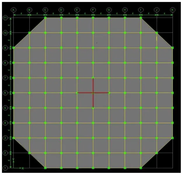
Geometrical Properties
1.No.of stories of the Building model=20 2.Column size=500 mm x 500 mm 3.Beam size= 700 mm x 500 mm 4.Slab thickness=200mm Loads
1.Live Load=3KN/m2 2.Wall Load=12.4KN/m 3.Floor Finishing =1KN/m2 4. Wind load
Wind coefficients (i) Wind Speed=50m/s (ii)Terrain Category =2 (iii) Structure Class=B (iv) Risk Coefficient(k1)=1 (v)Topography(k3)=1 Seismic loading
(i) Seismic zone factor(Z)=0.36 (ii) Soil Type= Medium(II)
(iii) Response Reduction factor(R) =5% (iv) Story Range=Base to 20
w w w . a j e r . o r g
Page 192
Material Properties
Table I The materials used in structure and their general properties are
Material Unit
weight
Elastic
Modulus Shear Modulus
Poisson Ratio
Thermal expansion coefficient
Text KN/m3 KN/m2 KN/m2 Unit less 1/C
Concrete 23.563 24855578.28 10356490.95 0.2 0.0000099
Rebar
steel 76.973 199947978.8 76903068.77 0.3 0.0000117
Bar steel 76.9730 199947978.8 769030068.77 0.3 0.0000117
Load Combinations
Load combination is the foremost important criteria for designing any structure and more important is the distribution of those loads on to various components of the structure like beams, columns, slabs and in our case shears walls and concrete core wall too. There are many kinds of loads existing depending on the location of the where the structure is to be constructed for example in a place where wind is frequent there we have to consider the wind loads and places where rains are heavy rain loads are included and same way all the other loads such as snow loads, earthquake load and etc. are included however DEAD LOADS, LIVE LOADS AND IMPOSEDLOADS are always included. Dead loads are all common depending onthe structural components and specific gravity of the structure, to get the self weight of the structural component volume or area of the component is multiplied by the specific gravity of the component. Live loads depend on the purpose we are constructing the building. Imposed loads depend on the seismic loads, dead loads and according to are 1893 part 1 percentage of those values is finally considered.
w w w . a j e r . o r g
Page 193
Figure2: Basic Plan of The Building
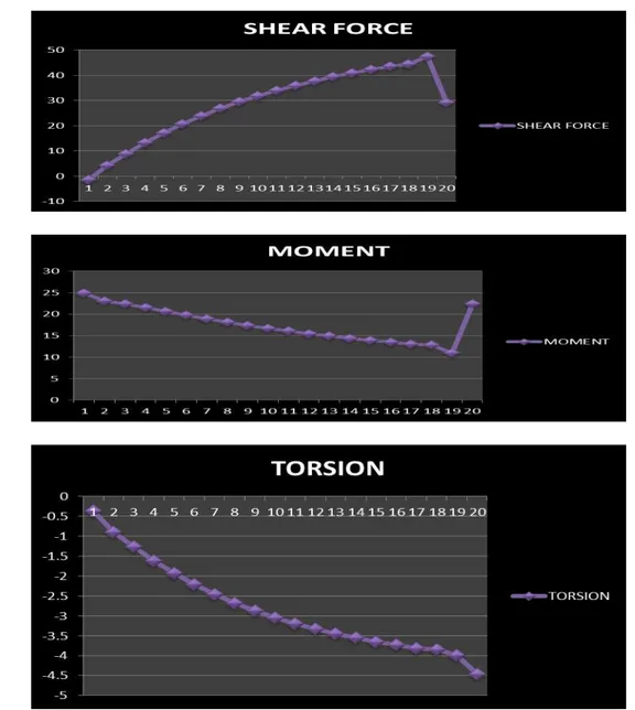
Table II: Shear Force, Torsion and Moment for Beam B1
Story Beam Load Loc AXIAL FORCE SHEAR FORCE TORSION MOMENT
STORY1 B1 1.2DLLLWLX 2.25 0 -1.53 -0.372 24.927
STORY2 B1 1.2DLLLWLX 2.25 0 4.28 -0.893 23.077
STORY3 B1 1.2DLLLWLX 2.25 0 8.83 -1.261 22.389
STORY4 B1 1.2DLLLWLX 2.25 0 13.15 -1.617 21.487
STORY5 B1 1.2DLLLWLX 2.25 0 17.1 -1.932 20.602
STORY6 B1 1.2DLLLWLX 2.25 0 20.69 -2.214 19.736
STORY7 B1 1.2DLLLWLX 2.25 0 23.92 -2.463 18.908
STORY8 B1 1.2DLLLWLX 2.25 0 26.84 -2.683 18.126
STORY9 B1 1.2DLLLWLX 2.25 0 29.47 -2.878 17.39
STORY10 B1 1.2DLLLWLX 2.25 0 31.84 -3.049 16.702
STORY11 B1 1.2DLLLWLX 2.25 0 33.99 -3.2 16.058
STORY12 B1 1.2DLLLWLX 2.25 0 35.93 -3.334 15.457
STORY13 B1 1.2DLLLWLX 2.25 0 37.71 -3.452 14.897
STORY14 B1 1.2DLLLWLX 2.25 0 39.33 -3.556 14.374
STORY15 B1 1.2DLLLWLX 2.25 0 40.82 -3.65 13.886
STORY16 B1 1.2DLLLWLX 2.25 0 42.2 -3.732 13.438
STORY17 B1 1.2DLLLWLX 2.25 0 43.49 -3.811 12.995
STORY18 B1 1.2DLLLWLX 2.25 0 44.42 -3.849 12.841
STORY19 B1 1.2DLLLWLX 2.25 0 47.46 -3.996 10.936
w w w . a j e r . o r g
Page 194
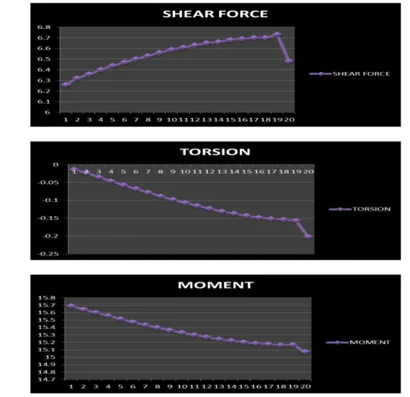
Figure 3: Shear Force, Torsion and Moment for Beam B1 Table III :Shear Force, Torsion and Moment for Beam B10
Story Beam Load Loc AXIAL FORCE SHEAR FORCE TORSION MOMENT
STORY1 B10 12DLLLWLX 2.25 0 6.26 -0.014 15.691
STORY2 B10 12DLLLWLX 2.25 0 6.32 -0.023 15.645
STORY3 B10 12DLLLWLX 2.25 0 6.36 -0.035 15.601
STORY4 B10 12DLLLWLX 2.25 0 6.4 -0.046 15.559
STORY5 B10 12DLLLWLX 2.25 0 6.44 -0.057 15.517
STORY6 B10 12DLLLWLX 2.25 0 6.47 -0.068 15.476
STORY7 B10 12DLLLWLX 2.25 0 6.5 -0.078 15.437
STORY8 B10 12DLLLWLX 2.25 0 6.53 -0.088 15.4
STORY9 B10 12DLLLWLX 2.25 0 6.56 -0.098 15.364
STORY10 B10 12DLLLWLX 2.25 0 6.59 -0.107 15.331
STORY11 B10 12DLLLWLX 2.25 0 6.61 -0.115 15.299
STORY12 B10 12DLLLWLX 2.25 0 6.63 -0.123 15.271
STORY13 B10 12DLLLWLX 2.25 0 6.65 -0.131 15.245
STORY14 B10 12DLLLWLX 2.25 0 6.66 -0.137 15.223
STORY15 B10 12DLLLWLX 2.25 0 6.68 -0.143 15.204
STORY16 B10 12DLLLWLX 2.25 0 6.69 -0.148 15.188
STORY17 B10 12DLLLWLX 2.25 0 6.7 -0.152 15.176
STORY18 B10 12DLLLWLX 2.25 0 6.7 -0.154 15.167
STORY19 B10 12DLLLWLX 2.25 0 6.73 -0.157 15.169
w w w . a j e r . o r g
Page 195
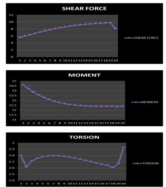
Figure 4:Shear Force, Torsion and Moment for Beam B10 Table IV: Shear Force, Torsion and Moment for Beam B20
Story Beam Load Loc AXIAL FORCE SHEAR FORCE TORSION MOMENT
STORY1 B20 1.2DLLLWLX 2.25 0 5.47 2.791 14.587
STORY2 B20 1.2DLLLWLX 2.25 0 5.88 2.613 14.206
STORY3 B20 1.2DLLLWLX 2.25 0 6.26 2.709 13.834
STORY4 B20 1.2DLLLWLX 2.25 0 6.65 2.75 13.526
STORY5 B20 1.2DLLLWLX 2.25 0 7.03 2.777 13.272
STORY6 B20 1.2DLLLWLX 2.25 0 7.39 2.79 13.062
STORY7 B20 1.2DLLLWLX 2.25 0 7.72 2.795 12.889
STORY8 B20 1.2DLLLWLX 2.25 0 8.02 2.791 12.749
STORY9 B20 1.2DLLLWLX 2.25 0 8.29 2.783 12.638
STORY10 B20 1.2DLLLWLX 2.25 0 8.54 2.77 12.55
STORY11 B20 1.2DLLLWLX 2.25 0 8.76 2.755 12.482
STORY12 B20 1.2DLLLWLX 2.25 0 8.95 2.737 12.432
STORY13 B20 1.2DLLLWLX 2.25 0 9.12 2.717 12.398
STORY14 B20 1.2DLLLWLX 2.25 0 9.26 2.697 12.375
STORY15 B20 1.2DLLLWLX 2.25 0 9.39 2.676 12.363
STORY16 B20 1.2DLLLWLX 2.25 0 9.49 2.655 12.36
STORY17 B20 1.2DLLLWLX 2.25 0 9.57 2.641 12.359
STORY18 B20 1.2DLLLWLX 2.25 0 9.64 2.602 12.383
STORY19 B20 1.2DLLLWLX 2.25 0 9.73 2.663 12.333
w w w . a j e r . o r g
Page 196
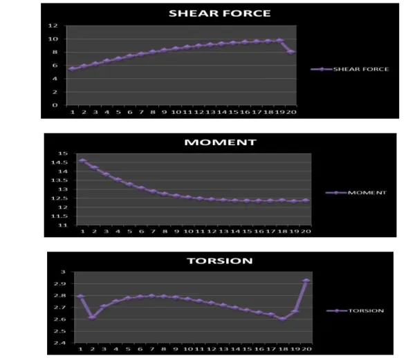
Figure 5:Shear Force, Torsion and Moment for Beam B20 Table V: Shear Force, Torsion and Moment for Beam B1
Story Beam Load Loc AXIAL FORCE SHEAR FORCE TORSION MOMENT
STORY1 B1 1.2DLLLEQY 2.25 0 -1.53 -0.372 24.927
STORY2 B1 1.2DLLLEQY 2.25 0 4.28 -0.893 23.077
STORY3 B1 1.2DLLLEQY 2.25 0 8.83 -1.261 22.389
STORY4 B1 1.2DLLLEQY 2.25 0 13.15 -1.617 21.487
STORY5 B1 1.2DLLLEQY 2.25 0 17.1 -1.932 20.602
STORY6 B1 1.2DLLLEQY 2.25 0 20.69 -2.214 19.736
STORY7 B1 1.2DLLLEQY 2.25 0 23.92 -2.463 18.908
STORY8 B1 1.2DLLLEQY 2.25 0 26.84 -2.683 18.126
STORY9 B1 1.2DLLLEQY 2.25 0 29.47 -2.878 17.39
STORY10 B1 1.2DLLLEQY 2.25 0 31.84 -3.049 16.702
STORY11 B1 1.2DLLLEQY 2.25 0 33.99 -3.2 16.058
STORY12 B1 1.2DLLLEQY 2.25 0 35.93 -3.334 15.457
STORY13 B1 1.2DLLLEQY 2.25 0 37.71 -3.452 14.897
STORY14 B1 1.2DLLLEQY 2.25 0 39.33 -3.556 14.374
STORY15 B1 1.2DLLLEQY 2.25 0 40.82 -3.65 13.886
STORY16 B1 1.2DLLLEQY 2.25 0 42.2 -3.732 13.438
STORY17 B1 1.2DLLLEQY 2.25 0 43.49 -3.811 12.995
STORY18 B1 1.2DLLLEQY 2.25 0 44.42 -3.849 12.841
STORY19 B1 1.2DLLLEQY 2.25 0 47.46 -3.996 10.936
w w w . a j e r . o r g
Page 197
Figure 6:Shear Force, Torsion and Moment for Beam B1 Table VI: Shear Force, Torsion and Moment for Beam B10
Story Beam Load Loc AXIAL FORCE SHEAR FORCE TORSION MOMENT
STORY1 B10 1.2DLLLEQY 2.25 0 6.26 -0.014 15.691
STORY2 B10 1.2DLLLEQY 2.25 0 6.32 -0.023 15.645
STORY3 B10 1.2DLLLEQY 2.25 0 6.36 -0.035 15.601
STORY4 B10 1.2DLLLEQY 2.25 0 6.4 -0.046 15.559
STORY5 B10 1.2DLLLEQY 2.25 0 6.44 -0.057 15.517
STORY6 B10 1.2DLLLEQY 2.25 0 6.47 -0.068 15.476
STORY7 B10 1.2DLLLEQY 2.25 0 6.5 -0.078 15.437
STORY8 B10 1.2DLLLEQY 2.25 0 6.53 -0.088 15.4
STORY9 B10 1.2DLLLEQY 2.25 0 6.56 -0.098 15.364
STORY10 B10 1.2DLLLEQY 2.25 0 6.59 -0.107 15.331
STORY11 B10 1.2DLLLEQY 2.25 0 6.61 -0.115 15.299
STORY12 B10 1.2DLLLEQY 2.25 0 6.63 -0.123 15.271
STORY13 B10 1.2DLLLEQY 2.25 0 6.65 -0.131 15.245
STORY14 B10 1.2DLLLEQY 2.25 0 6.66 -0.137 15.223
STORY15 B10 1.2DLLLEQY 2.25 0 6.68 -0.143 15.204
STORY16 B10 1.2DLLLEQY 2.25 0 6.69 -0.148 15.188
STORY17 B10 1.2DLLLEQY 2.25 0 6.7 -0.152 15.176
STORY18 B10 1.2DLLLEQY 2.25 0 6.7 -0.154 15.167
STORY19 B10 1.2DLLLEQY 2.25 0 6.73 -0.157 15.169
w w w . a j e r . o r g
Page 198
Figure 7: Shear Force, Torsion and Moment for Beam B10 Table VII: Shear Force, Torsion and Moment for Beam B20
Story Beam Load Loc AXIAL FORCE SHEAR FORCE TORSION MOMENT
STORY1 B20 1.2DLLLEQY 2.25 0 5.47 2.791 14.587
STORY2 B20 1.2DLLLEQY 2.25 0 5.88 2.613 14.206
STORY3 B20 1.2DLLLEQY 2.25 0 6.26 2.709 13.834
STORY4 B20 1.2DLLLEQY 2.25 0 6.65 2.75 13.526
STORY5 B20 1.2DLLLEQY 2.25 0 7.03 2.777 13.272
STORY6 B20 1.2DLLLEQY 2.25 0 7.39 2.79 13.062
STORY7 B20 1.2DLLLEQY 2.25 0 7.72 2.795 12.889
STORY8 B20 1.2DLLLEQY 2.25 0 8.02 2.791 12.749
STORY9 B20 1.2DLLLEQY 2.25 0 8.29 2.783 12.638
STORY10 B20 1.2DLLLEQY 2.25 0 8.54 2.77 12.55
STORY11 B20 1.2DLLLEQY 2.25 0 8.76 2.755 12.482
STORY12 B20 1.2DLLLEQY 2.25 0 8.95 2.737 12.432
STORY13 B20 1.2DLLLEQY 2.25 0 9.12 2.717 12.398
STORY14 B20 1.2DLLLEQY 2.25 0 9.26 2.697 12.375
STORY15 B20 1.2DLLLEQY 2.25 0 9.39 2.676 12.363
STORY16 B20 1.2DLLLEQY 2.25 0 9.49 2.655 12.36
STORY17 B20 1.2DLLLEQY 2.25 0 9.57 2.641 12.359
STORY18 B20 1.2DLLLEQY 2.25 0 9.64 2.602 12.383
STORY19 B20 1.2DLLLEQY 2.25 0 9.73 2.663 12.333
w w w . a j e r . o r g
Page 199
w w w . a j e r . o r g
Page 200
Figure 9:Story Drift in X and Y Direction
IV.
DISCUSSION ON RESULTS
The structural prototype is prepared and lots of data is been collected from the prototype. All the aspects such as safety of structure in shear, moment and in story drift have been collected. So now to check whether to know whether the structure is safe with established shear walls and all construction of core wall in the center we need to compare the graphical values of structure with the shear wall and a simple rigid frame structure.
Story Drift
w w w . a j e r . o r g
Page 201
parameters to observe the effect on the drift (lateral deflection) of the tall building due to both wind and earthquake loading. There are three major types of structures were identified in this study, such as rigid frame, coupled shear wall and wall frame structures.
Is 1893 Part 1 CodalProvoisionsForStoreyDriftLimitations
The storey drift in any storey due to the minimum specified design lateral force, with partial load factor of 1.0, shall not exceed 0.004 times the storey height For the purposes of displacement requirements only, it is permissible to use seismic force obtained from the computed fundamental period (T) of the building without the lower bound limit on design seismic force specified in dynamic analysis.
V.
CONCLUSION
It is evident from the observing result that the shear wall are making value of torsion very low.
The story drift for the combination load DL+LL+WLx in X&Y direction shown same performance for the building, and less value for story drift in all combinations at story 20.The value of story drift is very low because of adding shear walls to the building.
It is evidentfrom the observing result that for combination loads 1.2 DLLLWLX&1.2DLLLEQY ,maximum value of moment at story one and minimum value of shear force also at story one . The Moment is maximum when the shear force is minimum or changes sign.
Based on the analysis and discussion ,shear wall are very much suitable for resisting earthquake induced lateral forces in multistoried structural systems when compared to multistoried structural systems whit out shear walls. They can be made to behave in a ductile manner by adopting proper detailing techniques.
The vertical reinforcement that is uniformly distributed in the shear wall shall not be less than the horizontal reinforcement .This provision is particularly for squat walls (i.e. Height-to-width ratio is about 1.0).However ,for walls whit height-to-width ratio less than 1.0, a major part of the shear force is resisted by the vertical reinforcement. Hence ,adequate vertical reinforcement should be provided for such walls.
VI.
VI.REFRENCES
[1] IS-456-2000-Code of Practice for Plane and Reinforced Concrete .
[2] IS 1893(Part 1)-2002:Eriteria for Earthquake Resistant Design of Structure .
[3] IS:875(Part1)-1987- Code of Practice for Design Load(other than earthquake) for Buildings andStructure –Dead loads
[4] IS:875(Part2)-1987- Code of Practice for Design Load(other than earthquake) for Buildings andStructure –Imposed Load
[5] IS:875(Part2)-1987- Code of Practice for Design Load(other than earthquake) for Buildings andStructure –Wind Load
[6] Mark fintel-Hand Book of Concrete Engineering. Second Edition .CBS Publishers &Distributors-New Delhi,2004
[7] Anil k.Chopra-Dynamics of Structure :Theory and Application to Earthquake Engineering, SecondEdition ,Pearson Education (Singapore) Pvt.Ltd 2005
[8] Mariopaz-Structure Dynamics : Theory and Computations,(Second Edition) , .CBS Publishers&Distributors-New Delhi,2004
[9] Indian Society of Earthquake Technology –Proceedings of the Sixth World Conference EarthquakeEngineering,Vol.1,Published by Sarita Prakashan,Merut,1977.
[10] A.r.chandrasekharan and D.s.prakashrao –a Seismic Design of Multi –Storied RCC Buildings (published in the proceeding ot the 12th symposium on earthquake engineering held iit-roorkee in dec 2002)
[11] Medhekar,m.s,andJain,s,k, Seismic Behavior ,Design and Detailing of RC Shear Wall,part 1:behavior and strength –an icj compilation .
[12] Kaustubhdasgupta ,C.v.r.murty and Shaileshk.agrawal,Seismic Shear Design of RC Structural Walls897-971.
[13] Crandell, J., and S. Herrenbruck. 2006.Residential wall bracing principles and design options. Journal of Building Safety. August2006
w w w . a j e r . o r g
Page 202
Author’s Profile:
I. Dr, Hadihosseini,Aerospace Engineering , working in International Earthquake Research Center of America (IERCA)
II. Mahdi hosseini , Master of Technology in Structural Engineering, Dept. of Civil Engineering, Jawaharlal Nehru Technological University Hyderabad (JNTUH), Hyderabad, Telengana , India
Research interest: Structural Engineering, StructuralDynamics, Structural Optimization, structural design, Reinforced Concrete Structures, Finite element analysis, Earthquake Engineering