Strength evaluation of concrete corbels
cast in a diferent stage of columns
Avaliação da resistência de consolos de
concreto moldados em etapa distinta do pilar
Abstract
Resumo
The design of a precast structural system requires joints between the structural elements, being often used concrete corbels in connection be-tween beams and columns. Concrete corbels are an obstacle to optimize the precast production mainly of column has two or more concrete cor-bels in diferent faces. In this cases, the concrete corcor-bels have needed to manufacture in distinct stage of column, which requires some attention to the interface between column and corbel and some solution to ensure the continuity of main tie reinforcement. This paper carried out some tests, analytical and computational modeling of ive models of concrete corbels, being one monolithic and four models with corbels are manufactured in distinct stage of the column. The results presented and discussed are the failure mode, the interface gap and the accuracy of the analytical and computational predictions. It was observed that the concrete corbels with bent tie reinforcement presented the largest gap opening in interface and that the computational model represented the monolithic concrete corbel resistance better than normative models.
Keywords: reinforced concrete, precast, corbels, computational modeling.
O uso de consolos de concreto é prática comum na ligação entre vigas e pilares, porém um entrave à sua utilização é a logística de concretagem quando os consolos de um pilar apresentam direcionamentos em diferentes planos. Surge, então, a necessidade de se realizar a concretagem do consolo e do pilar em etapas distintas, o que exige alguns cuidados com a interface e alguma solução para que exista continuidade entre as armaduras. Este trabalho faz análises experimentais, normativas e computacionais de cinco modelos de consolos, sendo um monolítico e quatro concretados em etapa distinta do pilar. Nos resultados são apresentados e discutidos os mecanismos de ruptura, as aberturas de junta, bem como a precisão das previsões analíticas e do modelo computacional. Ao inal do trabalho se observou que os consolos com tirante dobrado apresentaram as maiores aberturas de junta, e que o modelo computacional representou melhor a resistência da biela comprimida do consolo monolítico que os modelos normativos.
Palavras-chave: concreto armado, pré-moldados, consolos, modelagem computacional.
a Universidade Federal de Goiás, Goiânia, GO, Brasil; b Pontifícia Universidade Católica de Goiás, Goiânia, GO, Brasil.
Received: 02 Jun 2016 • Accepted: 30 Ago 2016 •Available Online: 17 Apr 2017
D. L. ARAÚJO a
S. A. AZEVEDO a
E. M. OLIVEIRA a
E. M. O. SILVA a
L. A. OLIVEIRA JÚNIOR b
1. Introduction
Industrialization of civil construction is gradually improving. The use of precast concrete in structural conception must be high-lighted. This structural system provides some adaptations of cer-tain work-related, environmental, and economic requirements that traditionally have not been prioritized, that is: high quality control, shorter construction time, saving materials and reducing waste; im-proved service behavior, and increased durability, among others. Prefabrication of structures has some implications for the design and execution of structures because, unlike structures that are cast in place, the connections between structural elements are not monolithic, and, therefore, distribute loads and provide structure stability in a diferent way.
Among the several types of connections between precast beams and columns, connections with corbels are the most common. Corbels are cantilevered elements projected from any structural element in order to provide support to other structural elements. The arrangement of beams in relation to the column afects the direction of the corbels.
Depending on the required position of corbels in the column, their manufacture needs to be realized in a diferent stage from the column in order to simplify the formworks. However, to perform this procedure, continuity between corbels and columns reinforce-ments should be guaranteed, which can be done by bending the main reinforcement of the corbels in the column or by splicing bar systems, such as the sleeves and threads system. In addition, the treatment of the interface between the column and corbel should
be performed with some care in order to provide efective bonding and transmission of internal forces between these elements. The objective of this research was to develop a comparative study of the strength and mechanical behavior between precast corbels cast in a diferent stage from the column, and monolithic corbels. For this, tests were conducted along with Finite Element Method computational modeling and analysis using design code models. In the case of corbels cast in a diferent stage, the inluence of the method used to perform the continuity of the main tie reinforce-ment with column reinforcereinforce-ment was analyzed. Also, the possibil-ity of replacing the secondary reinforcement required in design of concrete corbels with steel ibers was veriied.
1.1 Design models for concrete corbels
The corbel design models are related to their failure modes, that is, the mode that requires the least energy dissipation for the failure of element. The failure mechanisms of corbels can be divided in six basic modes: bending, concrete crushing on the strut, shear at the interface between the corbel and the column, loss of anchorage of the main tie reinforcement, horizontal load, and concrete crushing under the bearing pad. Figure 1 illustrates those mechanisms. Corbels, in general, are classiied as three-dimensional elements, since they do not have enough length to dissipate localized dis-turbances. Thus, the hypothesis of lat sections in lexure (Navier-Bernoulli’s hypothesis) is not valid, which invalidates the beam theory in these cases. Figure 2 provides an overview of the stress paths in corbels. Figure 2a shows a bottom portion of the corbel
Figure 1
without stresses, which justiies the use of the geometries shown in Figure 2b.
From Figure 2, a large concentration of parallel solid lines on the upper face of corbels can be observed, which means that this region has a high concentration of tension stress. On the other hand, parallel dashed lines from the application point of the load to the base of the corbel can be observed, which represent a compressed region of the corbel. From this stress overview, the strength mechanism of the corbels can be approached by a strut and tie model. In these models, regions under tension are replaced by tie reinforcement and a concrete strut replaces the compressed region. Thus, the internal forces can be obtained and design of corbel can be performed.
Strut and tie models are the basis of most design models recom-mended by national and international design codes for monolithic concrete corbels. In this paper, recommendations of Brazilian codes for precast concrete structures [2], European code [3] and Precast/Prestressed Concrete Institute (PCI) recommendation [4] were adopted for analysis.
1.2 Steel iber-reinforced concrete
Plain concrete is a brittle material that shows low strain before reaching its ultimate strength. Moreover, it has high compressive strength, but low tension-strength. The addition of steel ibers to the cementitious matrix can improve its mechanical behavior. According Özcan et al. [5], the addition of steel ibers to concrete
improves the cracking process of the matrix, making the material more ductile. Moreover, the addition of ibers to the fresh con-crete does not require major changes in traditional practices of concrete casting.
The contribution of steel ibers in the cementitious matrix is mainly related to its random distribution, that is, as the cracks appear, ibers cross the cracks and transfer tension forces between the
crack faces. Thus, the cracking process becomes more distributed in the cementitious matrix and do not concentrate in very small re-gions, thus resulting in a higher number of cracks of reduced sizes, which increases the ductility of the concrete.
Gao and Zhang [6] claim that the use of steel iber reinforced con-crete in the prefabrication of corbels reduces the reinforcement ratio of the corbel and increases its strength and stifness, thus improving its mechanical behavior.
2. Experimental program
Five concrete corbels with the geometry shown in Figure 3 and properties listed in Table 1 were tested. This geometry was ad-opted so that the failure load estimated for the monolithic model was lower than the capacity of reaction frame used in the tests. The symmetry of the model, with two corbels, is particularly in-teresting in the execution of the tests, as it avoids the need for a
Figure 2
Stress paths in corbels. Adapted from Torres [1]
Figure 3
reaction structure to prevent the rotation of the column, which hap-pens when the model has a single corbel. According to Table 1, model P1 was monolithic, while models P2 to P5 had the corbels cast in a diferent stage from the column. Furthermore, the corbels of model P2 were produced using a concrete reinforced by 1% (78.5 kg/m3) of steel ibers.
2.1 Materials
The concrete used in the corbel tests was composed of Port-land Cement type CP II-Z, silica fume, crushed powder, natural sand, coarse aggregate with two maximum dimensions, wa-ter and superplasticizer. Steel ibers used were DRAMIX® RC 65/35 BN with 35 mm length, 0.54 mm diameter and nominal strength of 1100 MPa, according to information provided by the manufacturer.
Tests to characterize the steel and concrete were performed in a universal electro-mechanic test machine with a capacity of 300 kN. The steel was characterized according the standard method of NBR 6892-1 [7], while the hardened concrete was characterized for compressive strength by NBR5739 [8], for modulus of elasticity by NBR 8522 [9], and for splitting tension strength by NBR 7222 [10]. Table 2 shows the values obtained for the mechanical proper-ties of concrete used in the research.
In addition, the mode I fracture energy for plain concrete was also determined. Then, it was used as recommend in RILEM [11], however a prismatic test specimen was used with a square cross section with 10 cm width and 40 cm length, and notched in the middle span at a depth equal to half of the specimen height. This
property was used in computational modeling of monolithic corbel. Detail of the reinforcements for the model of the monolithic corbel (P1) are shown in Figure 4, and for models with corbels cast in a diferent stage from the column (models P2, P3, P4, and P5) in Figures 5, 7, and 8. All models were designed to fail by lex-ure due to the yielding of the main tie reinforcement. Models P4 and P5 had two main ties of 16 mm diameter made of CA 25 type steel, and were designed to achieve failure strength equal to 80% of the strength of the monolithic model, which had two main ties of 12.5 mm diameter mad of CA 50 type steel. These models were produced in a precast concrete industry. Model P3, on the other hand, had two main ties of 12.5 mm diameter made of CA 25 steel, and theoretical strength equal to 50% of the strength of the mono-lithic model.
Model P2 had two main ties of 12.5 mm of diameter made of CA 50 steel and, therefore, the same theoretical strength as the mono-lithic model. Splicing of the main reinforcements was performed using a system of sleeves and threads, according to Figure 6. The sleeves were pressed at the ends of the bars and joining was per-formed by means of a threaded stud. The length of each sleeve (H) was 68.75 mm. Models P3, P4, and P5 had main ties made of CA 25 steel, which were bent into the mold before the casting of column and rectiied prior to casting of the corbels. The anchorage of the main reinforcement at the ends of the corbels for all models was guaranteed by means of a welded transversal bar with the same diameter.
The bars spliced by sleeves and threads were tested in tension to determine the mode and the ultimate strength of bars, as shown in Figure 9. After, the sleeve was cut and only a bar of 12.5 mm was
Table 1
Properties of tested models
Model Interface treatment Fiber content Main reinforcement Secondary reinforcement
P1 Monolithic 0% Continuous Horizontal and vertical stirrups
P2 Shear key 1% Sleeve and threads Horizontal loops without stirrups
P3 Scarified rough joint 0% Continuous(a) Horizontal stirrups in CA 25 and
vertical stirrups
P4 Scarified rough joint 0% Continuous(a) Horizontal stirrups in CA 25 and
vertical stirrups
P5 Scarified rough joint 0% Continuous(a) Horizontal stirrups in CA 25 and
vertical stirrups
Note: a) Main and secondary reinforcements, made of CA-25 steel, were bent in the formwork of the column before casting and turned straight
after its demolding.
Table 2
Mechanical properties of concrete
Model
Compressive strength fcm (MPa)
Elasticity modulus Ec (GPa)
Tensile strength by diametrical compression
fctm,sp (MPa)
Fracture energy Gf (N/m)
Column Corbel Corbel Column Corbel Column
and corbel
P1 50.48 ± 1.34 27.80 ± 1.34 5.09 ± 0.26 97.050 ± 9.374
P2 62.43 ± 6.88 55.86 ± 2.21 31.17 ± 1.08 5.94 ± 1.30 8.35 ± 1.18
-P3 43.09 ± 1.34 46.85 ± 0.27 28.45 ± 0.21 4.02 ± 0.32 4.26 ± 0.06
-P4 26.30 20.84 25.65 2.42 2.18
-tested in tension according to NBR 6891-1 [7]. Table 3 shows re-sults of the characterization of the steel used in the reinforcement of the models. The modulus of elasticity of the steel bars was equal to the theoretical value, that is, 210 GPa for all models.
2.2 Construction and testing of models
Steel formworks were used for casting models. The formwork was adapted for casting both monolithic models and models with
Figure 4
Reinforcement detailing of model with monolithic corbel (P1)
Figure 5
Figure 6
Scheme of splice with sleeves and threads for model P2 with corbels cast in different stages of the column
Figure 7
corbels cast in a diferent stage from the column (Figure 10). For this adaptation, there was a side closure for the casting column, which was subsequently replaced by the corbels formwork.
Monolithic model P1 was cast in one stage, while for models P2, P3, P4, and P5 the side of the formwork was removed two days af-ter the casting of the column. Corbels were cast afaf-ter the assembly
Figure 8
Reinforcement detail of models with corbels cast in different stage from the column (P4 and P5) with bent
main reinforcement
Figure 9
of corbel reinforcements and were kept in a humid chamber for two days. After this time, the models were demolded and kept outdoors until the date of testing.
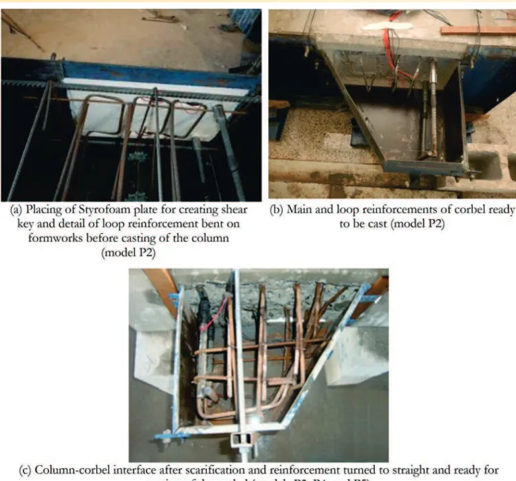
Two diferent surface treatments were analyzed for the column-corbel interface of the models cast in two stages. For model P2, with main ties connected by sleeve and threads, a 2.5 cm-deep single shear key was added to the interface; that is, a depression was created on the surface of column to avoid the interface being located on the column face. To create this shear key, a plate of Styrofoam was glued to the face of the formwork before casting the column, which was removed before casting of corbel (Figures 11a and 11b). For models P3, P4, and P5, where the main and secondary reinforcements are bent into the column, scariication of concrete was performed on the interface, as shown in Figure 11c. The scariication process was performed during the removal of su-pericial concrete from column at the corbel region in order to make the main and secondary reinforcements straight. The interface was cleaned and washed before casting the corbels in order to improv-ing the bond between the concretes of the column and corbel. The presence of secondary reinforcement does not make the production of monolithic corbels more inconvenient. On the oth-er hand, in models with corbels cast during a difoth-erent stage from the column, secondary reinforcement has to be supplemented later during the assembly of corbel reinforcement. This implies intensive human resources and delay in casting of the corbels. In addition, some additional reinforcements are necessary, such
as vertical stirrups and other constructive reinforcements. As an attempt to reduce the time spent on the manufacture of cor-bels cast in a diferent stage from the column, model P2 was pro-duced without secondary reinforcement and vertical stirrups, which were replaced by steel ibers added to the concrete. However, as Oliveira [12] reports, steel ibers are ineicient to control the joint gap at the column-corbel interface; therefore, a horizontal loop reinforcement crossing the interface was used for this in the P2 model. To simplify the process and avoid cuts in steel formwork, this reinforcement was left bent into the column formwork. The an-chorage length of this loop reinforcement in the corbel was the minimum required and, in this test, was equal to 6.3 cm, which was measured from the external column face. This length was equal to the spacing between loops in order to allow its settlement within the column formwork without reinforcement overlap, as shown in Figure 11a.
Tests were carried out with models upside down. In models P1, P2 and P3 the corbels were simply supported, that is, one ixed and one moving support, to avoid horizontal external loads. In models P4 and P5 the corbels already had two ixed supports. The pur-pose of this change was to identify the inluence of the support type on the corbel strength. Figure 12 shows the test setup. The axis of the supports was placed 22.5 cm away from the column face, so that corbels had an applied load eccentricity-to-depth ratio (a/d) equal to 0.62; thus characterizing them as short corbels according to NBR9062 [2]. Furthermore, supports were 5 cm wider in models
Table 3
Mechanical properties of steel
Diameter
Ø (mm) / Type of steel Models
Yield strength fy (MPa)
Ultimate stress - fu
(MPa) Yield strain - ey
6.3 / CA50 P1 and P2 615.27 ± 18.06 695.97 ± 7.74 2.92 × 10
-3
P3 620.56 ± 38.77 714.54 ± 43.51 2.95 × 10⁻³
12.5 / CA50 P1 670.18 ± 7.63 785.99 ± 12.23 3.19 × 10
-3
P2(a) 541.11 ± 11.95 634.58 ± 12.23 2.57 × 10⁻³
12.5 / CA25 P3 409.97 ± 8.79 508.78 ± 9.03 1.95 × 10
-3
P4 and P5(b) - Not tested
-Note: (a) Specimen tested with joining by sleeves and threads; (b) Steel not tested: the theoretical value of yield stress, fy = 250 MPa was
considered applicable.
Figure 10
P1 and P2, 10 cm wider in model P3 and 15 cm wider in models P4 and P5. Again, the purpose of these changes was to verify the inluence of the width of the support in the corbel strength. Loading was applied to the column using a hydraulic actuator con-nected in series with a load cell. Thus, the load applied in each corbel was half of the value registered by the load cell.
Models were instrumented with displacement transducers and strain gages. Displacement transducers were used to register the vertical displacement and the joint gap opening on the column-cor-bel interface. On the other hand, strain gages were used to register strains of the main and secondary reinforcements, as well as the strain of the horizontal loop reinforcement crossing the interface. Figure 12b shows the model instrumentation.
3. Computational modeling
The model with monolithic corbel (P1) was computational modeled
to identify the principal stresses in corbel. For this, the software DIANA® 9.5 [13] based on Finite Element Method was used. Pre-vious studies showed that the computational modeling by Finite Element Method is eicient to represent the mechanical behavior of concrete corbels [14].
3.1 Geometry and mesh
Initially, a convergence analysis was performed in elastic range to deine the optimal size of the mesh. Figures 13b, 13c and 13d show the three meshes analyzed and Table 4 shows the dis-placements obtained for model. The less reined mesh 1 shows displacement in the bottom of the model equal to 97.7% of the displacement obtained with the more reined mesh 3. However, although it demanded longer processing time, the more reined mesh 3 was adopted, with quadratic interpolation element CHX60 and approximate size of 3 cm in the corbel region.
Figure 11
Corbel and column reinforcements were represented by embed-ded reinforcement in concrete. Thus, there is no need to create a mesh of linear elements with node compatibility with the solid ele-ments mesh. This formulation is valid in terms of stifening of the elements in contact with the embedded reinforcement. Figure 12a showed the reinforcement of the computational model.
In addition to representing the column, the corbels, and their re-inforcements, the support plates were also modeled, according to test sizes, in order to ensure that the strut width in computational model was the same.
3.2 Constitutive models
Computational analysis was carried out considering physical non-linear constitutive models available in the software and the used design codes. For concrete a smeared crack model was used, formulated in terms of total strains with ixed cracks (Total Strain Fixed Crack). Under tension, concrete behavior was represented by means of a linear softening law, which depends on the mode I fracture energy (Gf), obtained from the characterization of concrete according to Figure 14a.
For the compressive behavior of concrete, the stress-strain curve recommended by FIB [15] was adopted (Figure 14b). From the compressive strength and the standard deviation of concrete, the characteristic strength and its class were obtained; thus, the stress-strain curve according to FIB [15] was obtained.
The von Mises model represents the steel by considering perfect elastoplastic behavior (Figure 14c), which is consistent with the yield strain observed in the characterization tests.
Table 5 summarizes the parameters adopted for the concrete and reinforcements in DIANA© 9.5 [13] for the computational modeling.
3.3 Processing
Displacement was imposed on the upper surface of the model. The value imposed was greater than that observed in tests and the pro-cessing was executed until there was no further convergence. The increment in the displacement value was set at 0.05 mm through-out the analysis and the equation system was solved using the Secant Method, which was executed by parallel processing. Con-vergence criterions, in terms of energy, with a tolerance of 0.001 were used.
4. Results and discussions
Results are divided into experimental results and computational modeling results. Subsequently, the results are compared with de-sign code recommendations for reinforced concrete corbels.
4.1 Experimental results
Table 6 shows the strength of corbels due to yielding of the main reinforcement (Fy,exp), and due to concrete crushing on the strut (Fu,exp). The following nomenclature is adopted for description the models: corbel A for the corbel that failed, usually on the moving supports; and corbel B for the other corbel.
Cracks in the monolithic model (P1) started in the region between the corbel and column, followed by cracks in the strut region, which increased in length and amount as the load increased. The yielding of main reinforcement started at the same loading level at which the corbel failed. The yielding load was determined when the average strain, measured by strain gages, of main reinforcement reached the yield of steel bar (Table 3). This model failed by concrete crushing in the upper corner of corbel A when the load applied to the corbel was 316.30 kN. The cracking pattern is shown in Figure 15a.
Figure 12
Test setup and instrumentation
Table 4
Parameter of meshes adopted for convergence test
Parameter Mesh Less refined Average More refined Number of
elements 156 832 1680
Number of nodes 1047 4437 8557
Figure 13
In the model with corbel cast in a diferent stage from the column, and with main reinforcement spliced by sleeves and threads (mod-el P2) cracks started on the column-corb(mod-el interface. Subsequent-ly, cracks started in the strut region of corbel A and the number and length of these cracks increased with increasing of load. The yielding of the main reinforcement began in corbel A at a load of 301.41 kN, and when the strain gages of the main reinforcement reached the yield of steel bar (Table 3). In this case, due to the presence of steel ibers, the concrete did not fail by crushing on the strut, and the mechanism of failure seems to be shifted to the column-corbel interface. A trend of concrete crushing in the upper
corner of the corbel was observed. The maximum load supported by the corbel was 357.57 kN. The crack pattern of this model can be observed in Figure 15b.
In the model with the corbel cast in a diferent stage from the col-umn and with a bent main reinforcement (model P3) cracks also started on the column-corbel interface. The length and the width of these cracks increased as the load increased. The irst crack in the central portion of the corbel, which deined the strut region and its path, arose when the load applied to the corbel reached 195.00 kN. These cracks increased in length and number as the load increased up to the point that the model failed, which occurred
Table 5
Parameters used in computational modeling
Parameter Value
Concrete
Compressive strength 50.48 [MPa](a)
Modulus of Elasticity 36.30 [GPa](b)
Tensile Strength 4.58 [MPa](c)
Mode I fracture energy 97.05 [N/m](a)
Behavior in compression Multilinear(b,d)
Behavior in tension Linear softening(d)
Shear retention factor 0.01 (constant) (d)
Cracking model Total Strain Fixed Crack(d)
Steel (Main reinforcement)
Yield stress 670.18 [MPa](a)
Behavior in tension Ideal plasticity of von Mises(d)
Modulus of Elasticity 210 [GPa]
Steel (Secondary reinforcement)
Yield stress 615.27 [MPa](a)
Behavior in tension Ideal plasticity of von Mises(d)
Modulus of Elasticity 210 [GPa]
Note: (a) Experimental results; (b) Recommendation by FIB [15]; (c) Adopted as 0.9 fctm,sp ; (d) Models available in DIANA© [13].
Figure 14
Table 6
Experimental results
Model Fy,exp (kN) Fu,exp (kN) Failure mode
P1 316.30 316.30 Concrete crushing of strut
P2 301.41 357.57 Flexure
P3 156.07 223.11 Flexure-compression
P4 * 260.04 Concrete crushing of strut
P5 * 271.32 Concrete crushing of strut
Note: *Main reinforcement not instrumented for testing.
Figure 16
at a loading of 223.11 kN. The crack pattern of this model is shown in Figure 15c.
In Model P4, which was cast in a diferent stage from the column and has a bent main reinforcement, cracks started on the column-corbel interface when the load applied to the column-corbel was 70.00 kN. Subsequently, more cracks arose in the main reinforcement region near to the column, when the load was 178.00 kN. The corbel failed at a load of 260.04 kN. Figure 15d shows the crack pattern of the corbel.
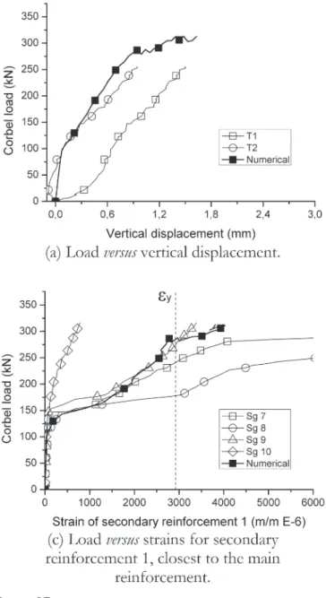
In model P5, also cast in a diferent stage from the column and with bent reinforcements, cracks started on the column-corbel interface when the load applied to the corbel was 73.0 kN. Subsequently, cracks in the main reinforcement region arose near to the column. Cracks in the strut arose when the load was 200 kN and propa-gated up to the upper corner, resulting in failure by crushing of concrete. The crack pattern of this model is shown in Figure 15e. Figure 16 shows, as a function of the load applied to the corbel, vertical displacements of the models and strain of the main and secondary reinforcements, as well as the joint gap openings. Only strains in the failed corbel are shown (corbel A), which were
obtained from the average strain measured on the corbel reinforce-ments. Vertical displacement was obtained from the average of two transducers and the joint gap opening was obtained from the average of four transducers positioned on column-corbel interface. It is noted from Figure 16a that the vertical displacement was simi-lar in models P1 and P2, and that model P3 showed much lower stifness than others. The model with the monolithic corbel (model P1) showed the lowest initial strain in the main reinforcement due to the greater crack load at the column-corbel interface in this mod-el, as shown in Figure 16b.
Horizontal loop reinforcement in model P2, nearest to main rein-forcement, showed larger strain than was observed in the second-ary reinforcement of the monolithic model (Figure 16c). This is due to the failure mode by lexure for model P2 with the corbel cast in a diferent stage from the column.
Joint gap opening for corbels with bent main reinforcement, that is, models P3, P4, and P5, had larger openings than corbels with main reinforcements spliced by sleeves and threads (model P2) (Figure 16e). This model, however, had a larger joint gap open-ing than model P1 with the monolithic corbel. This analysis was
Figure 17
performed by comparing joint gap openings of models under the same load; for example, for the service load of the mono-lithic model, estimated at 150.00 kN, as it can be seen in Fig-ure 15e.
4.2 Computational modeling
Results from computational modeling of the monolithic corbel (model P1) are shown in Figures 17 and 18. It can be seen from Figure 17b that there was a good agreement of experimental and numerical strains of the main reinforcement, as was report-ed in other works [14]. As observreport-ed in the experimental tests, the failure of the corbel in the computational model happened at a load level whereby the strain of the main reinforcement was close to the steel yield. However, in the computational model cracks on the column-corbel interface start at a load lower than that observed in experiments (Figure 17b) due to the premature loss of stifness in the computational model compared to the experimental results.
Strain in the secondary reinforcement closest to the main tie rein-forcement obtained from computational modeling, showed good agreement with the experimental results, and was close to the yield-ing of reinforcement. However, the second layer of secondary rein-forcement showed stifer numerical results, although the yielding of
reinforcement in this layer was close to the failure of the corbel. During tests a noticeable strain variation on the same reinforce-ment layer of corbels is noted. This is probably due to the rota-tion of the model around its longitudinal axis, which could ex-plain the diferences observed in the two vertical transducers (Figure 17a). For this, the analysis of strain obtained from the computational models was performed for both corbels and not only for the failed corbel A. Furthermore, for each corbel, indi-vidual values of strain measured by the strain gages were used instead averaged values.
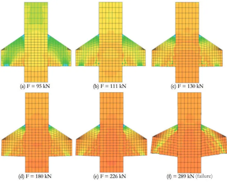
Figure 18 shows the evolution of the compressive principal stress (S3) on the models as the load increases. The forma-tion of the strut in the initial load levels can be observed, be-fore concrete cracking at the column-corbel interface. After the formation of cracks on the interface, the strut becomes less evident and there is a concentration of stresses at the bottom of the corbel, which show compressive stress greater than the concrete compressive strength during the final stages of load-ing. Furthermore, the strut width at the bottom of the corbel has no correspondence with the width of the support. It is clear from the computational modeling that the failure of this corbel was defined by the crushing of concrete on the node formed on the support of the strut and not by crushing of the strut in the inner region of corbel.
Figure 18
Principal stresses of compression of the computational model (S3) with loading increment
4.3 Comparison with design code models
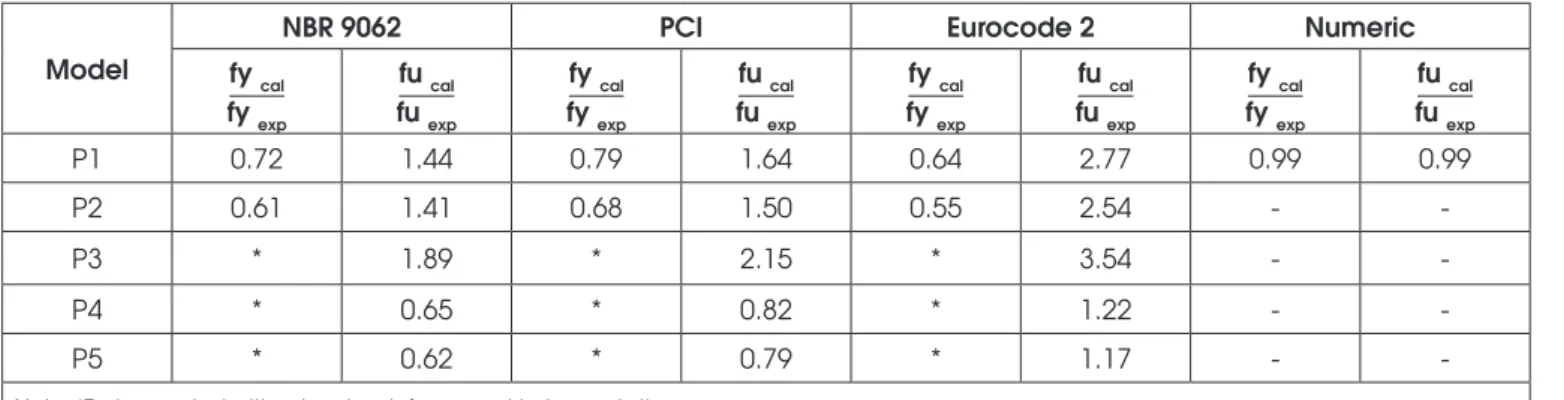
Table 7 compares experimental results to the strength of corbels obtained from design codes and from computational modeling. Both the load corresponding to yielding strength of main the re-inforcement and the failure load due to concrete crushing on strut are analyzed.
Values shown in Table 7 allow assessment of the accuracy of the design code prescriptions and computational modeling to predict the tests results. It is shown that the computational modeling per-formed the best prediction of the monolithic corbel strength and that design code models provided conservative values for the yielding strength of the main reinforcement of the corbels, with the best prediction being made by the PCI [4] model.
On the other hand, NBR 9062 [2] and PCI [4] design codes over-estimated the strut strength for corbel models P1, P2, and P3, and underestimated the strength for corbel model P4, and P5. The Eu-rocode 2 [3] design code provided unsafe values.
Due to the variation of compressive strength of concrete in the ive models, a veriication of the eiciency of design code models was performed using the compressive stress on the strut when the cor-bels fail. This stress was compared to the compressive strength of concrete obtained from characterization tests. Theoretical evalua-tion of the stress on the strut at corbel failure was performed using equilibrium forces in a strut-and-tie model with geometry shown in Figure 19. The strut width was taken as constant as computational modeling did not indicate an inluence of the support width. More-over, it was taken equal as 20% of the efective depth of the corbel, since previous studies have shown that this is the strut width in monolithic corbels [16].
Table 8 shows that when models P1, P2, and P3 failed the
compressive stress on the strut had not yet reached the compres-sive strength of concrete. This indicates that in these corbels the failure may have happened on node, as shown by computational modeling. On the other hand, models P4 and P5 reached failure when the strut was subjected to stress greater than compressive strength of concrete. This happened because models P4 and P5, as opposed to the others, were tested with two ixed supports, and therefore, they were subjected to horizontal forces of unknown val-ues. The presence of compressive horizontal forces on the corbels afects the equilibrium of forces on the strut and tie model and al-ters the slope and resultant force acting on the strut. Therefore, it is shown that the support type inluences the corbel strength. Models tested with one moving support (without horizontal force) failed at
Table 7
Comparison between prediction and experimental strengths of corbels
Model
NBR 9062 PCI Eurocode 2 Numeric
fy cal fy exp
fu cal fu exp
fy cal fy exp
fu cal fu exp
fy cal fy exp
fu cal fu exp
fy cal fy exp
fu cal fu exp
P1 0.72 1.44 0.79 1.64 0.64 2.77 0.99 0.99
P2 0.61 1.41 0.68 1.50 0.55 2.54 -
-P3 * 1.89 * 2.15 * 3.54 -
-P4 * 0.65 * 0.82 * 1.22 -
-P5 * 0.62 * 0.79 * 1.17 -
-Note: *Test executed without main reinforcement instrumentation
Figure 19
Geometry used for equilibrium of forces and
delimitation of the strut width to verify the
efficiency of design code models
Table 8
Comparison between concrete compressive strength
(f
cm) and strut failure stress (
σ
u,strut)
Model fcm
(MPa) (MPa)σu,strut σu,strut / fcm
P1 50.48 37.85 0.75
P2 62.43 42.79 0.69
P3 43.09 26.70 0.62
P4 26.30 31.12 1.18
the node when the compressive stress on the strut was lower than the compressive strength of concrete.
5. Conclusion
The main conclusion is that corbels cast in a diferent stage from the column show greater joint gap opening than monolithic corbels, even if it does not necessarily involve a reduction in the failure load of the corbel. That is, test show that the main reinforcement of corbels cast in a diferent stage from the column reached the yield stress of steel before the failure of the corbels. Monolithic model (P1) showed the lowest values of joint gap opening, fol-lowed by model P2, with the main reinforcement spliced by sleeves and threads. Models P3, P4, and P5, in which main reinforcements were bent between cast steps, showed values of joint gap open-ing up to four-times greater, relative to service load. In this case, the value of joint gap opening exceeded the crack limit of 0.4 mm width deined by Brazilian codes, which implies problems of struc-tural durability for this construction solution. On the other hand, model P2 showed a joint gap opening with value close to the limit of 0.4 mm for service load.
Crack patterns in model P2 were much more distributed than in model P1, which was monolithic, despite the absence of second-ary reinforcement in model P2, which was cast in a diferent stage from the column. This implies the ability of steel ibers to transfer stress across the cracks after the steel yields. On the other hand, the cracking pattern of model P2 suggests a change in the failure mode of the corbel, which started by bending and was followed by failure due to the node crushing at the corbel base.
In model P2, where sleeves and threads spliced the main forcement, no reduction of the strength by yielding of the main rein-forcement and by crushing concrete on the strut was shown when compared to the monolithic corbel. Moreover, it was easier to exe-cute and had higher strength than the other models produced with reinforcements bent on column formworks before casting. This suggests the applicability of the solution of corbels cast in a difer-ent stage from the column with the main reinforcemdifer-ent spliced by sleeve and thread, and with secondary reinforcements replaced by steel ibers added to concrete.
Numerical modeling showed good agreement with experimental re-sults of the monolithic corbel, not only for strength loads, but also for the model behavior throughout loading evolution. In addition, the estimated failure load for the monolithic corbel was closer to the ex-perimental results than that given by the design code models. Design code models were conservative in terms of their evaluation of yielding strength of the main reinforcements for the models of monolithic corbels and with corbels cast in a diferent stage from the column when sleeves and threads spliced the main reinforce-ment. However, the PCI model [4] was the one that showed the best agreement with experimental results from these corbels. All design code models overestimated the strength of the strut in corbels P1, P2, and P3 without horizontal force due to moving sup -ports. Moreover, it was observed that the best and safest prediction of the failure load was observed for corbels with two ixed supports. Therefore, veriication of the strength of the strut of corbels subject-ed to vertical loadings seems to be inadequate and unsafe, depend-ing on the support conditions of the beams on the concrete corbels.
6. Acknowledgments
The authors wish to thank the Brazilian National Council of Re-search and Development (CNPq) for inancing this reRe-search (Proj-ect number 552118/2011-7). They also wish to thank the Brazilian companies Belgo Bekaert Arames and Goiás Artefatos de Cimento – Goiarte for donating the materials used in the research and the Brazilian Coordination for the Improvement of Higher Education Personnel (CAPES) for granting a scholarship. Authors thank specially to civil engineer Helen Oliveira Tenório for her support in producing the models, Matheus Silva for his support with computa-tional modeling, and Breno Pedreira Landim and Carlos Godoy de Castro by their support during the testing.
7. References
[1] TORRES, F. M. Theoretic-experimental analysis of rein-forced concrete corbels. Dissertation (Master Science in Structural Engineering) – Engineering School of São Carlos, São Paulo University, São Carlos, 1998 (In Portuguese). [2] ASSOCIAÇÃO BRASILEIRA DE NORMAS TÉCNICAS.
Design and execution of precast concrete structures. NBR 9062, Rio de Janeiro, 2006, 41 p. (In Portuguese).
[3] COMITÉ EUROPÉEN DE NORMALISATION - CEN. EN 1992-1-1:2004 - Eurocode 2: Design of concrete structures - Part 1.1: General rules and rules for buildings. Brussels, Belgium, 2004, 225 p.
[4] PRECAST/PRESTRESSED CONCRETE INSTITUTE - PCI. PCI Design Handbook. 7. ed. Chicago, 2010.
[5] ÖZCAN, D. M.; BAYRAKTAR, A.; AHIN, A.; HAKTANIR, T.; TÜRKER, T. Experimental and inite element analysis on the steel iber-reinforced concrete (SFRC) beams ultimate behavior. Construction and Building Materials, 2009, 23(2), 1064–1077.
[6] GAO, D. Y.; ZHANG, J. Finite element analysis of shear be-haviors for steel iber reinforced concrete corbels by ANSYS.
In: Second International Conference on Computer Modeling and Simulation, Proceedings, 2010, 4, 303-307.
[7] ASSOCIAÇÃO BRASILEIRA DE NORMAS TÉCNICAS. Me-tallic materials — Tensile testing Part 1: Method of test at room temperature. NBR ISO 6892-1, Rio de Janeiro, 2013. 70p. (In Portuguese).
[8] ASSOCIAÇÃO BRASILEIRA DE NORMAS TÉCNICAS. Con-crete - Compression test of cylindric specimens - method of test. NBR 5739, Rio de Janeiro, 2007. 9p. (In Portuguese). [9] ASSOCIAÇÃO BRASILEIRA DE NORMAS TÉCNICAS.
Con-crete - Determination of the elasticity modulus by compres-sion. NBR 8522, Rio de Janeiro, 2008, 16 p. (In Portuguese). [10] ASSOCIAÇÃO BRASILEIRA DE NORMAS TÉCNICAS.
Concrete and mortar - Determination of the tension strength by diametrical compression of cylindrical test specimens. NBR 7222, Rio de Janeiro, 1994, 3 p. (In Portuguese). [11] RILEM DRAFT RECOMMENDATION, TC 50-FMC
[12] OLIVEIRA, E. M. Reinforced concrete corbels cast in two stages: Inluence of interface treatment and steel ibers ad-dition. Dissertation. (Master Science in Civil Engineering) – Civil Engineering School, Federal University of Goiás, Goiâ-nia, 2012 (In Portuguese).
[13] TNO Building and Construction Research. DIANA User’s Manual – Release 9.5. Delft, Netherlands, 2014.
[14] CANHA, R. M.F.; KUCHMA, D. A.; EL BEBS, M. K.; SOUZA, R.A. Numerical analysis of reinforced high strength concrete corbels. Engineering Structures, 2014, 74, 130–144. [15] INTERNATIONAL FEDERATION FOR STRUCTURAL
CON-CRETE – FIB. Model Code 2010, Volume 1. Bulletin 65. In-ternational Federation for Structural Concrete (FIB), Switzer-land, 2012.
![Table 5 summarizes the parameters adopted for the concrete and reinforcements in DIANA © 9.5 [13] for the computational modeling.](https://thumb-eu.123doks.com/thumbv2/123dok_br/18861717.418074/10.892.63.827.63.406/table-summarizes-parameters-adopted-concrete-reinforcements-computational-modeling.webp)