Efect of the modiication by titanium dioxide nanotubes with diferent structures on the
fatigue response of Ti grade 2
Leonardo Contri Campanellia*, Paulo Sergio Carvalho Pereira da Silvaa, Nilson Tadeu Camarinho
Oliveirab, Claudemiro Bolfarinia
Received: September 17, 2016; Revised: February 24, 2017; Accepted: May 1, 2017.
Nanotechnology is seeing as having potential to raise beneits to several research and application
areas. Recently materials with nanostructured surfaces of nanopores, nanotubes and nanowires
have become an important investigation ield, since their chemical and physical properties may be substantially diferent from those of the corresponding substrate. In face of the necessity of assuring that such modiications are not deleterious to the mechanical behavior, the purpose of this work was to evaluate the fatigue performance of CP-Ti grade 2 with the surface modiied by the formation of nanotubes on their diferent crystalline structures. The nanotubes layers were produced by anodic
oxidation using a potential of 20V during 1h and a solution of glycerol, H2O and NaF, and analyzed
by scanning electron microscopy. In order to obtain the anatase and rutile structures, annealing
treatments were respectively performed at 450°C and 650°C. The axial fatigue tests were conducted in physiological solution at 37°C following the stepwise load increase approach. When compared to
the material without surface modiication (polished surface), the results showed that the anatase phase did not afect the fatigue response, maintaining the fracture stress in 500 MPa, whereas the rutile phase
caused a decrease to 450 MPa.
Keywords: titanium, surface modiication, nanotubes, fatigue
* e-mail: [email protected]
1. Introduction
Nanotechnology has been explored as a tool for the surface
modiication of Ti and its alloys for implants applications,
for instance with the growth of nanotubular and nanoporous oxide layers1,2. It has been extensively shown that nano-scale
oxide coatings are able to increase the surface bioactivity and consequently the osseointegration phenomenon3. Salou
et al.4 studied the osseointegration behavior of Ti-6Al-4V implants with diferent surface morphologies after four weeks
of implantation in the femoral condyle of rabbits. By these
in vivo tests, it was testiied that the nano-modiied surface
resulted in improved osseointegration when compared to
the modiied surfaces at the micrometer level. Within the most cost-efective possibilities to achieve nano-scale oxide
coatings is the anodic oxidation process, which allows the
growth of diferent morphologies according to the electrolyte composition. When luoride-containing electrolytes are
used, it is probable that self-organized and highly ordered layers of nanotubes arrays are obtained, typically with an amorphous structure5. It is known that the crystal structure of these layers can be modiied by post-annealing treatments,
inducing the enhanced formation of a hydroxyapatite layer6.
Due to the great sensitiveness to the surface condition, the fatigue performance is always a great concern when
surface modiication of implants is performed. In the case
of a nanotubes coating, Bortolan et al.7 did not observe a deleterious efect of the coating itself on the fatigue response
of Ti-6Al-4V, which was mainly attributed to the nano-scale
thickness of the modiied layer. The amorphous structure plays
an important role, since it allows the elastic deformation of
the oxide layer in a degree suicient to avoid the generation of surface cracks8. However, when the amorphous structure
is changed to a crystalline one, the introduction of residual stresses may become the main factor controlling the fatigue behavior. Apachitei et al.9 veriied a signiicant inluence of
residual stresses on the fatigue response of plasma electrolytic oxidized Ti-6Al-4V and Ti-6Al-7Nb with coatings of several
micrometers of thickness.
The aim of this work is a preliminary assessment of the
fatigue performance of CP-Ti coated with an array of TiO2
nanotubes in diferent crystal structures.
2. Materials and Methods
The material employed in this work was rounded bars of CP-Ti (grade 2) in accordance with the requirements of
a Department of Materials Engineering, Federal University of São Carlos, Rod. Washington Luís,
km. 235, 13565-905, São Carlos, SP, Brazil
ASTM F67 standard. Cylindrical fatigue specimens were machined following the geometrical aspects of ASTM E466 standard, grinded with silicon carbide emery papers and polished with diamond pastes up to 1 µm. Anodic oxidation was therefore employed to obtain the nanotubes layer using an Agilent 6575A-J07DC power supply and a two electrode
system, with the Ti as the working electrode and a 304
stainless steel plate as the counter electrode. A solution of glycerol, H2O (50:50 vol.%) and 0.31M NaF was used as
the working electrolyte and a potential of 20V was applied
during 1h at room temperature, without stirring10.
In order to change the oxide structure, annealing treatments
in air were performed during 3h in the temperatures of 450 and 650°C, with subsequent air cooling. The surface morphologies
were evaluated by scanning electron microscopy (SEM) in a FEI Magellan 400 L microscope. X-ray difraction (XRD) analyses were conducted in a Siemens D5005 difractometer with CuKα radiation. The phases were identiied by matching the difractograms to the JCPDS iles and the XRD patterns
were indexed through the Crystallographica Search-Match 2.1.1.1 software.
Axial fatigue tests were conducted in a MTS Bionix servo hydraulic testing machine, employing a simple physiological
solution (9 g/L NaCl) at 37°C, a frequency of 10 Hz and
a stress ratio R = 0.1. Stepwise load increase tests were applied, in which the maximum stress started at 150 MPa and was increased by steps of 50 MPa every 5x10⁴ cycles
until the rupture. This method has been used as a low-time consuming approach aiming at the preliminary evaluation
of the surface modiication efect on the fatigue response,
and therefore three replicates were adopted to provide the arithmetic mean of the fatigue fracture stress.
3. Results and Discussion
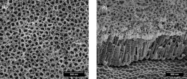
Figure 1a brings a SEM micrograph of CP-Ti after anodization in the conditions aforementioned. The surface
Figure 1. SEM micrographs of CP-Ti after anodization at 20V and 1h: (a) top view and (b) cross-section.
typically consists of a well-organized and homogeneous arrangement of nanotubes with, under the employed
conditions, an average diameter of 90 nm. It is known that
the underlying microstructure of CP-Ti is fully comprised by alpha phase, in which the growth of nanotubes proceeds during the anodization process without any problems11. In
Figure 1b, the cross-section micrograph of a mechanically scratched region also shows an organized arrangement of nanotubes, allowing the determination of their average length
of approximately 1 μm. It is noteworthy the undulations
observed in the substrate when the nanotubes layer was
removed, which are not expected to work as mechanical
notches due to their nano-scale dimension.
It is a well-established concept that the anodic oxidation
treatment results in an amorphous oxide structure over the CP-Ti substrate. When the anodized samples were heat treated at both temperatures, no changes in the nanotubes morphologies were detected. Nevertheless, the oxide structures
were conirmed to be changed into crystalline anatase and
rutile at respectively 450°C and 650°C. These results are in accordance to the structural transformation by annealing of TiO2 nanotubes layer in Ti systems, as mentioned in the literature2,7,12. An example of these indings is shown
in Figure 2, where the micrograph of the nanotubes layer
after 450°C treatment is presented, and the XRD pattern of
such condition is compared with the one of the as-formed
nanotubes condition. It is clear that the oxide layer maintains
the morphological features after the heat treatment and that the anatase phase is formed in this case, which were similarly noted after the 650°C treatment except for the rutile formation predominance.
The fatigue performance of the 450°C annealed nanotubes layer characterized by the stepwise load increase tests is presented in Figure 3. The maximum stress and the resultant maximum displacement are plotted against
the number of cycles. If tangent lines are hypothetically
Figure 2. SEM micrograph and XRD pattern of the nanotubes layer after annealing at 450°C, along with XRD pattern of the as-formed condition.
Figure 3. Stepwise load increase plot for the specimens annealed at 450°C.
is signiicantly increased in the stress levels above 500 MPa for two specimens (and above 450 MPa for one specimen), which may indicate that macro-crack nucleation may have
occurred. All specimens, however, failed with a few cycles
(lower than 30,000) in the stress of 500 MPa. In the case
of the specimens treated at 650°C, the curves presented in Figure 4 reveal that the displacement increase, as well as
the specimens fracture, occurs with a few cycles (lower than 25,000) in the stress of 450 MPa.
It is important to note that no microstructural alterations of the CP-Ti substrate were veriied after the heat treatments. In addition to the fact that the morphologies and dimensions
of the nanotubes layers were similar prior and after the annealing treatments, the changes in the fatigue performance
may be explained by the diferences of the oxide crystalline
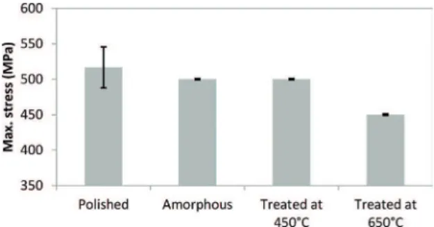
structure. A summary of the fatigue fracture results in all surface conditions is found in Figure 5. The average fracture stress of the amorphous and 450°C treated conditions is the same of the polished surface, but a reduction, albeit small, is
clear when the 650°C treated condition is considered (note the error bars in all conditions).
Figure 4. Stepwise load increase plot for the specimens annealed at 650°C.
Figure 5. Summary of the fatigue results obtained with the stepwise load increase tests.
One reason for the reduced fatigue performance of coated
specimens could be the generation of cracks in the nanotubes
oxide layer under cyclic loading. For the amorphous structure
of the oxide coating, a previous work of Campanelli et al.8 on Ti-6Al-4V veriied the absence of cracks after the fatigue
tests. This was attributed to an elastic behavior of the oxide
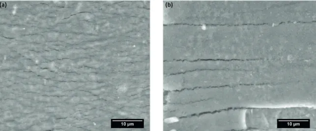
Figure 6. SEM micrographs of the nanotubes layer after the fatigue tests: (a) annealed at 450°C (anatase structure) and (b) annealed at 650°C (rutile structure).
fatigue response. In the present work, the crystallization of
the oxide may have changed the deformation behavior since
cracks were detected after the fatigue tests. As presented in Figure 6, several cracks can be observed in both specimens
treated at 450 and 650°C.
However, a fundamental diference is noticeable between the cracks pattern. In the case of rutile, fewer and larger cracks are observed in contrast to a large number of small cracks in the case of anatase. This can be attributed to the
formation of residual stresses, which are tensile for the rutile and compressive for the anatase structure13. In consequence, in the rutile layer the cracks grew reaching a critical size before the cracks in the anatase layer for the same substrate
material. Final fracture should therefore occur under smaller stresses in the case of rutile, as the fatigue results show in Figure 5. Such observation clearly shows the necessity of
a careful evaluation in the selection of surface modiication
treatments that are expected to improve the osseointegration behavior, since the solely change of the oxide structure, even
without modifying the nanotubes dimensions, may afect
the fatigue behavior.
4. Conclusions
A well-organized and homogeneous arrangement of nanotubes with 90 nm diameter and 1 µm length was obtained on CP-Ti. Subsequent crystallization of the oxide layer into anatase and rutile through annealing did not alter the morphological features. The fatigue study based on the stepwise load increase approach revealed
that the surface modiication with amorphous and anatase
phase resulted in a similar fracture stress of 500 MPa, but a reduction to 450 MPa was observed in the presence of rutile phase, suggesting caution in the design of surface
modiied implants.
5. Acknowledgements
The authors are grateful to the inancial support from FAPESP (grant 2012/01652-9 and scholarships 2013/04423-3 and 2016/12995-5).
6. References
1. Kapusta-Kołodziej J, Zaraska L, Sulka GD. Nanoporous anodic titania observed at the bottom side of the oxide layer. Applied Surface
Science. 2014;315:268-273.
2. Oliveira NTC, Verdério JF, Bolfarini C. Obtaining self-organized nanotubes on biomedical Ti-Mo alloys. Electrochemistry Communications. 2013;35:139-141.
3. Saji VS, Choe HC, Brantley WA. An electrochemical study on self-ordered nanoporous and nanotubular oxide on Ti-35Nb-5Ta-7Zr alloy for biomedical applications. Acta Biomaterialia. 2009;5(6):2303-2310.
4. Salou L, Hoornaert A, Louarn G, Layrolle P. Enhanced osseointegration of titanium implants with nanostructured surfaces: An experimental study in rabbits. Acta Biomaterialia. 2015;11:494-502.
5. Kulkarni M, Mazare A, Gongadze E, Perutkova Š, Kralj-Iglič V, Milošev I, et al. Titanium nanostructures for biomedical applications.
Nanotechnology. 2015;26(6):062002.
6. Minagar S, Berndt CC, Wang J, Ivanova E, Wen C. A review of the application of anodization for the fabrication of nanotubes on metal implant surfaces. Acta Biomaterialia. 2012;8(8):2875-2888.
7. Bortolan CC, Campanelli LC, Bolfarini C, Oliveira NTC. Fatigue strength of Ti-6Al-4V alloy with surface modiied by TiO2 nanotubes
formation. Materials Letters. 2016;177:46-49.
8. Campanelli LC, Bortolan CC, da Silva PS, Bolfarini C, Oliveira NT. Efect of an amorphous titania nanotubes coating on the fatigue and corrosion behaviors of the biomedical Ti-6Al-4V and Ti-6Al-7Nb alloys. Journal of the Mechanical Behavior of Biomedical Materials. 2017;65:542-551.
9. Apachitei I, Lonyuk B, Fratila-Apachitei LE, Zhou J, Duszczyk J. Fatigue response of porous coated titanium biomedical alloys.
10. Córdoba-Torres P, Oliveira NTC, Bolfarini C, Roche V, Nogueira RP. Electrochemical impedance analysis of TiO2 nanotube porous layers based on an alternative representation of impedance data. Journal of Electroanalytical Chemistry. 2015;737:54-64.
11. Macak JM, Tsuchiya H, Taveira L, Ghicov A, Schmuki P. Self-organized nanotubular oxide layers on Ti-6Al-7Nb and Ti-6Al-4V formed by anodization in NH4F solutions. Journal
of Biomedical Materials Research Part A. 2005;75(4):928-933.
12. Luo B, Yang H, Liu S, Fu W, Sun P, Yuan M, et al. Fabrication and characterization of self-organized mixed oxide nanotube arrays by electrochemical anodization of Ti-6Al-4V alloy.
Materials Letters. 2008;62(30):4512-4515.