Augmented Reality Experiments with Industrial
Robot in Industry 4.0 Environment
Ivo Mal´y
∗†, David Sedl´aˇcek
†and Paulo Leit˜ao
∗‡∗Polytechnic Institute of Braganc¸a, Department of Electrical Engineering, Braganc¸a, Portugal – [email protected]
† Czech Technical University in Prague, Faculty of Electrical Engineering, Czech Republic –{malyi1, sedlad1}@fel.cvut.cz ‡LIACC - Artificial Intelligence and Computer Science Laboratory, Porto, Portugal
Abstract—The role of human in the Industrie 4.0 vision is still considered as irreplaceable. Therefore, user interfaces of cyber-physical systems involved in the production automation need to be well designed and taking into consideration the industrial application requirements. With the advances in augmented and virtual reality data visualization and novel interaction techniques like mid-air gestures, these approaches seem to be suitable for integration into the industry environment. This paper describes the implementation of an augmented reality application for smart glasses with mid-air gestures and smart phone with touch interaction to compare and evaluate the usage of such interfaces in a production cell comprising an industrial robot.
I. INTRODUCTION
Current trends in Industrie 4.0 vision [1] show that the human interaction in Cyber-physical systems (CPS) cannot be eliminated but, in opposite, it should be supported and emphasized. Apparently, humans cannot be replaced by robots in some specialized product processing tasks, so the cooper-ation between humans and robots [2] needs to be supported. Users are also shifting from repeated manual work to more specialized roles. Such roles, as mentioned by Gorecky et al. [3], cover mainly servicing and maintenance of manufacturing plants, but also monitoring, planning, and simulation of pro-duction processes. To conclude that, human-system interaction must be developed as an integral part of CPS with respect to both user tasks but also human abilities and limitations.
The application of human factors in the development of products is intensively used in the human-computer interaction field. Methodologies like user-centered design (UCD) [4] that include the usage of prototyping tools, representation of target user groups in form of persons or task modeling, help to take the user into account in every step of the product development. The usage of these approaches increases the chance that the user interface and interaction will be usable, therefore improve the performance and cause fewer user errors. Initial research in the field of human-centered design in the context of CPS already started in the form of usability engineering in projects like ARVIKA [5]. Additionally, Romer et al. [6] recently showed how to develop applications for the Industrie 4.0 environment using the UCD methodology. Also Valdeza et al. [7] described how to use additional usability methods for decreasing the complexity of user interfaces applications in Industrie 4.0 environment.
The diversity of the activities in Industrie 4.0 vision is very big, spanning from the interaction with individual elements,
such as PLC (Programmable Logic Controllers) or robots, to management of the production at the SCADA (Supervisory Control and Data Acquisition) level. Therefore this paper focuses only on specific parts. Selected activities involve the presence of the user in the factory shop floor. Specifically, these activities involve mainly maintenance tasks, but also monitoring and planning tasks can be included. At this level, devices used for user interaction and data visualization are mo-bile devices (e.g., phones/tablets) and wearable smart glasses (e.g., look-through glasses). From the data presentation point of view, augmented reality (AR) and virtual reality (VR) ap-plications provide data in form of standardized graphical user interfaces, human-machine interfaces or graphical information as a part of AR or VR environment.
The objective of this paper is to describe the experiences with development of an AR application for augmentation of an industrial robot. The paper focuses on the description of the application requirements and prototype implementation. The initial version of the user interface is evaluated and results are discussed.
The rest of the paper is organized as follows: section II discusses related AR applications and experiments. Section III describes the requirements and the architecture for the devel-oped AR application. Section IV describes the implementation details of the AR application, including hardware and software components. In section V, the qualitative evaluation of the AR application is described and results from the evaluation are discussed in section VI. Finally, section VII rounds up the paper with conclusion and points out some future work.
II. RELATEDWORK
for projection of augmented data on real objects that are then perceived by users.
In the majority of projects related to industry environments, the main type of AR display used is HMD. A comprehensive overview of projects using AR in industry was presented by Ong et al. [10] and up-to-date research was also done by Garcia et al. [11]. One of the projects that focused on the development of AR applications in industry is ARVIKA project [5]. The goal of the project was to develop AR tech-nologies and applications to augment real-world field of view of various professions in automotive and aerospace industries, power and processing plants and machine tools and produc-tion machinery. Over 30 prototypes of AR applicaproduc-tions were developed in usability engineering and user-centric approach. In [12] Rainers et al. investigated the usage of AR and VR for assembly of door lock in automotive industry. Specifically in aerospace industry, De Crescenzio et al. [13] showed how maintenance tasks can be improved by augmented reality.
Other types of displays for AR/VR applications were also used in industry related projects. Olwal et al. [14] used the AR with projection technique for augmentation of process with a Computer Numerical Control (CNC) machine. Similarly, Zhou et. al. [15] used projection techniques combined with HMD for automotive production.
Complex model based AR visualization applications started to be developed in order to evaluate whole processes of production life-cycle. Penna et al. [16] presented web-based solution, Espindola [17] presented universal solution. The usage of AR in SmartFactory environment was presented by Paelke et al. [18].
This literature review shows that current approaches focus mainly on AR or VR applications in environments where the user is typically staying or sitting at specific places. In this work, the focus is on experiments with AR/VR applications that are used in environments where the user is moving around a real or virtual object that is being augmented or visualized by the application. Moreover, the user interaction with the AR/VR application is usually limited. In this paper we also investigate the suitability of the Leap motion device for mid-air gestures as an alternative mean of interaction to touch interface.
III. REQUIREMENTS ANDARCHITECTURE OFAR APPLICATIONS FORINDUSTRIALAUTOMATION Typical tasks in Industrie 4.0 environments need to combine several aspects:
• The distance of the augmented object from the user can
vary from several centimeters to several meters.
• The augmented object can vary in size from several
centimeters to several meters and can have various shapes and materials.
• The light and sound conditions may vary.
• The tasks that the user is performing may require usage
of one or both hands, or require user attention for some time.
Additionally, when AR applications are used in the UCD cycle, they need to:
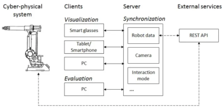
Fig. 1. Design of multilayer architecture of developed AR application.
• Support the observation and analysis of the user
interac-tion via data collecinterac-tion.
• Take into account data complexity of real manufacturing
processes for high fidelity prototyping.
• Allow prototyping and possibility for iterative
develop-ment.
Based on these aspects and requirements, a basic AR application structure was designed, as illustrated in Fig. 1. The AR application comprises 3 fundamental layers forming a client-server structure. The client layer involves client AR applications running on devices like smart glasses or tablets, depending on the task requirements like free hands or size of display. These client AR applications provide the visualization of AR data to the user, and based on the type of display, they may allow also the user input (e.g., touch interaction in case of mobile phones and tablets). A specific type of client AR applications is the evaluation client, that should be implemented as PC application due to the performance reasons. The evaluation client should allow control of the task flow during experiments and data collection that is important for understanding of AR application issues. The second layer consists of a server providing mainly synchronization of data among clients. Additionally, the server layer communicates with the third layer, which represents external data sources like inputs/outputs from the CPS that is being augmented. This helps researchers to make task believable and improves the quality of the evaluation.
IV. AR APPLICATIONIMPLEMENTATION
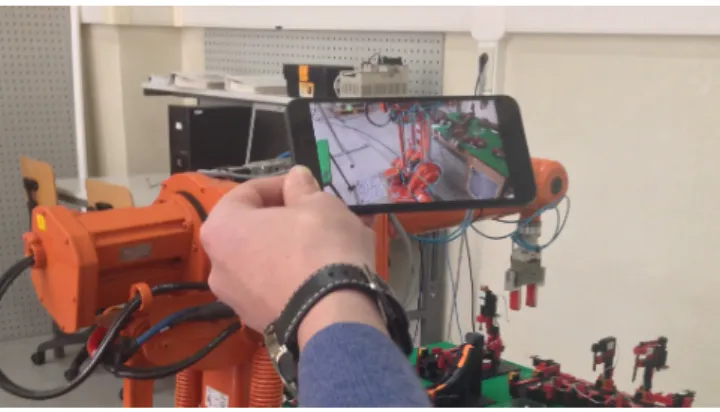
The AR application and experiments were implemented in a small scale production cell, illustrated in Fig. 2, which consists of several Fischertechnik workstations and one ABB IRB 1400 robot unit with controller and teaching pendant device. The robot tool configuration comprises a mechanic gripper for item holding using air pressure to pick/release the item. The robot is positioned in the middle of the system layout with workstations being disposed around the robot.
A. Tracking
Fig. 2. User using Epson Moverio smart glasses with AR application and Leap Motion controller.
detection and standard markers provided with Vuforia SDK [19] were used. The markers were arranged into multi-target marker setup (see MM marks in Fig. 3). Used Vuforia SDK brings also benefit in so calledextended trackingwhere other device sensors like accelerometers and gyroscopes are used together with on the fly scene reconstruction. Thus, the scene is tracked continuously even if all parts of multi-target marker are lost.
Due to the fact that the robot is not a static part of the environment, we chose another type of markers for the robot position detection. In this case, simplified frame markers were used (FM in Fig. 3) to allow the detection of the robot position without the direct connection to the robot data or interpretation of the robot program. There were several frame markers at axis 1, 2, and 3 that allowed the calculation of values of these axis, as illustrated in Fig. 3. See Vuforia SDK [19] for details about marker types and tracking details.
B. AR Applications
The AR applications for all platforms were developed using Unity3d [20]. This framework allowed to implement the structure of the AR application according to the planned architecture, including marker detection and client-server ar-chitecture.
Based on the literature search and manual for the ABB IRB 1400 maintenance, a basic set of tasks that will be provided in our AR application was detected. The tasks cover mainly the interaction with the robot from near distance (up to 6 meters). The list of implemented visual and interaction functions is listed as following and showed in Fig. 4 and in Fig. 5:
• Data visualization
– Icon visualization, e.g., detection of safe zone.
– Robot visualization using a virtual reality model, out-line augmentation of the robot and no visualization of virtual robot using depth mask.
– Highlighting robot parts by color.
MM
MM MM FM
FM
FM
Axis 1
Axis 2 Axis 3
Fig. 3. Robot visualization in base pose with multi-target marker composed of three markers (MM) and with four frame markers (FM). Axis 1, 2, and 3 are depicted, other four axis are hidden for simplicity.
Fig. 4. Various types of robot augmentation. In the left image, there is only highlighted part of the robot visible. In the middle image, there is outline of the robot visible. In the right image, whole virtual robot is visualized. Dark blue parts represent highlighted parts of the robot.
Fig. 5. Various types of specific point highlight visualization on the robot. In the left image the point is highlighted by 3D arrows. In the middle image the point is highlighted by leading line going from the left side of the screen to the down right point. In the right image the point is not directly highlighted but the state of the point is shown by text message.
– Highlighting specific points of the robot by 3D arrows.
– Navigation to invisible points on the robot using leading line.
– Providing instructions using text.
• Basic interaction using touch control and mid-air gestures
– Manipulation with robot by adjusting axis values.
– Navigation in menu structures.
Fig. 6. AR application run on Android smart phone.
Fig. 7. Evaluation application running on PC. Various settings of the client applications are set by buttons on the right side. Virtual robot in the middle reflects the visualization perceived by user of client application.
Moverio BT-200 smart glasses (see Fig. 2), which consist of two see-through displays for augmented reality and one cam-era on the side for environment sensing. The AR application was used in stereoscopic mode. In case of hand-held displays the AR application was developed for Android devices and the application was run in normal 2D mode (see Fig. 6). For evaluation of the AR application usage, the PC AR application was developed and used in 2D AR mode (see Fig. 7). The PC application was implemented so that it is merging the client and server layers into one, also providing operator with the functions to control the course of experiment and show how the user is performing and what he/she can see and do.
The interaction with the client applications was done using touch interaction on mobile devices and using Leap motion sensor with smart glasses. The Leap motion controller was not directly connected to the smart glasses, but it was connected to PC, due to the availability of drivers, without any significant impact on the user interaction experience.
V. AR APPLICATIONEVALUATION
The prototype AR application was evaluated in the small scale cell setup. The goal was to qualitatively analyze initial feedback of the test participants on individual types of the robot augmentation. In the study, there were 6 participants, who work as researchers and Ph.D. students in the field of CPS. All participants were given all of the following tasks:
1) ”You will see several types of augmented robot(outline, virtual robot, real robot)together with highlighted part of the robot. Evaluate, which type of visualization is most suitable for you.”
2) ”You will see three types of a specific point highlighting (by 3D arrow, leading line and text). Evaluate suitability of the highlighting.”
3) ”Use particular interaction technique (touch or Leap motion gestures) to manipulate virtual robot to the predefined position.”
4) ”Using particular interaction technique (touch or Leap motion gestures), evaluate basic set of gestures for navigation in maintenance task wizard.”
Participants performed the tasks with one device setup, then with the other. First half of the participants started with smart glasses and second half started with Android smart phone. At the beginning of each part, the users were given time to experience the usage of the devices.
Two types of the data were collected and analyzed during the evaluation, a) feedback given by participants from task execution, and b) evaluation of expected functionality from the observing application. The participants’ feedback was collected as immediate feedback expressed mainly vocally during the task execution. After completing the tasks, the participants were interviewed to summarize the use of the applications.
VI. RESULTS ANDDISCUSSION
Findings observed during the evaluation of AR applications can be divided into two groups. The first group is related to technical aspects and reflects technical findings. The second group focuses on subjective evaluation and observation of participants issues. In following subsections the major findings are discussed.
A. Limitation of the camera for frame marker detection
While the multi-target marker detection together with ex-tended tracking used for tracking of the user in the scene works very well on hand-held devices, we have observed problems with the detection and tracking with smart glasses. From the technical point of view, the marker detection can be separated in two different tasks. The first is the detection and recognition of marker. The second is the marker tracking. For the first phase, we evaluated that camera had to be closer to the marker and also the marker should be still. For the second case (we suppose successful marker recognition from first phase) the camera or marker can move up to some distance, where marker is lost. So the participant is limited by a distance of the camera from the marker and also by the speed of movement (faster moves causes tracking lost). The second criteria (speed) can be refined by higher camera frame rate (FPS); on the other hand, the detection algorithms need to process more frames so the hardware (CPU) limits the processing speed. Both factors influence the tracking stability on smart glasses.
The used frame marker size was47×47mm, and consists of 9 black or white squares separated by spaces of the same size. Based on our testing, we can say that a marker of this size is successfully recognized, if the marker resolution is at least 2mm/px. For example with a Tablet Nexus 10, we were able to detect and recognize markers from 0.98m distance and than the marker was tracked up to 1.5m. With smart glasses, the first detection was closer to the marker (0.6m) and tracking was lost at 1m distance. We observed that the marker detection is also dramatically affected by lighting conditions and camera contrast.
Epson (640x480px) Tablet (2560x1920px)
2.6m 0.47px/mm 0.36px/mm
22px/marker 17px/marker
1.6m 0.76px/mm 1.06px/mm
36px/marker 50px/marker
0.6m 2.12px/mm 3.04px/mm
100px/marker 143px/marker
The detection and tracking of multi-target markers had better performance mainly due to the markers size (A3 format) and availability of extended tracking. Successful detection starts at 2.5m distance for tablet and at 1.5m for glasses, and were tracked up to 4m and 2.5m respectively.
From the participants’ subjective point of view, we saw that the unstable glasses tracking caused issues with correct alignment of augmented data in real world and users had to pause the tasks in order to re-detect markers. This issue had impact on trust of the participants to AR visualization.
B. Limited field of view
The used AR glasses had a narrow field of view (23◦), i.e.
they covered only small part of human binocular vision system (114◦ and 190◦ including monocular sector [21]). This fact
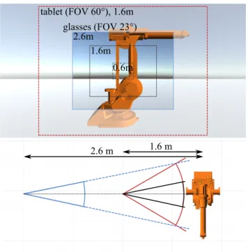
is limiting for real applications in two ways. First, the user had to stay far away from augmented object for overall view (approximately3min our case, see Fig. 8), thereby increasing the probability of user collision with the environment, which can be limiting in real factory environment. Second, in case of close detail, the user had to be informed about model changes and had to be guided (for example by line of sight) to look at other part of augmentation. Up to our knowledge the limited field of view is similar for all other optical see-through displays available currently on the market.
From participants’ point of view, we observed the difference between limitations of the visualization in tasks 1-2 and 3-4. In first two tasks the user did not complain about not seeing the complete robot. However, in latter two tasks they did. The difference may be the fact that in the first two tasks they only observed the robot; however, in second two tasks they had to additionally control the robot. Another reason may be the fact that in the first tasks they observed the augmented robot but in the second tasks they interacted only with the virtual robot.
C. Visualization techniques
The evaluation of the visualization techniques had focused on four major parts, namely visualization styles of robot
1.6 m 2.6 m
tablet (FOV 60°), 1.6m
2.6m 1.6m
0.6m glasses (FOV 23°)
Fig. 8. Comparison of visible area depending on the camera distance. The FOV of Moverio glasses (23◦) is depicted by cones a) and b) from distances 1.6m and 2.6m respectively. The close distance of glasses (0.6m) is not shown in bottom image. The c) cone corresponds to device with larger FOV (tablet). In top figure are depicted visible areas for tablet in 1.6m distance and for glasses from 2.6m, 1.6m, and 0.6m distances respectively (areas without white overlay).
augmentation, augmentation of spots by arrows, leading line and text.
1) Visualization styles: The evaluation of the visualization style of the robot showed that users preferred to see the robot either outlined or in full virtual reality. Only one user wanted to see invisible robot with highlighted parts only. The most probable reason is the fact that users wanted to be sure about matching parameters of the real and virtual robot.
2) Arrows: There were no issues with the usage of the arrows. All the users found the spots where arrows were pointing. The only case when the user missed the point was when the marker tracking was lost but the image of the robot was still shown, but not aligned. We also saw that when the arrow was occluded by the robot, the user had difficulty to find it, because he did not know, how many of arrows are shown. 3) Leading line: The leading line was visible, but no user fully understood its meaning and behavior. There was no clear difference between start and end point, so the users were not sure where it is pointing. Missing indication of the end point also caused that when the line went through the robot, it was not clear whether the intersection point is end point or not.
D. Interaction techniques evaluation
The evaluation of interaction styles compared the usage of Leap motion gestures and touch interaction.
1) Touch interaction: This interaction technique was easily understandable to the participants, even though it was not implemented optimally. Participants preferred the selection of axis and manipulation with objects in general using direct manipulation with parts of the robot.
2) Leap motion gestures: The users were able to use hand movement gestures to rotate the robot. They appreciated the speed of the movement compared to touch interaction, but were not satisfied by the quality of extended finger count detection and changes in hand count detection. These issues caused that some of the users were not able to finish the interaction with Leap motion.
VII. CONCLUSION
This paper describes the development of an AR application that augments an industrial robot for shop floor tasks like maintenance or cooperative work of human and robot. The AR application was designed and developed for smart glasses with Leap motion air-gestures and mobile phones with touch interaction. For visualization of the robot, the AR application is using outline, virtual or no visualization of the robot. For the visualization of the spots on the robot, the AR application is using 3D arrows visualization, leading line visualization and text visualization.
Six participants performed 4 tasks for evaluating the AR application and interaction techniques. We observed that lim-itations of the markers detection and limlim-itations of the field of view using smart glasses caused usability issues of the AR application for robot augmentation in our setup. Participants wanted to have complete knowledge about the virtual robot representation in the AR application and therefore selected the virtual robot or outline of the robot visualization style. Additionally, they were satisfied with the 3D arrow visualiza-tion and text visualizavisualiza-tion, but they refused the leading line concept of spot highlighting. In case of interaction with the AR application, the touch interaction was evaluated as more familiar then mid-air gestures. On the other hand, mid-air gestures were considered as faster, but some gestures with extended fingers were not correctly detected, which caused failure of task completion.
Future work is devoted to perform further qualitative and quantitative evaluation in environments where an AR ap-plication is connected to the robot controller, so that the visualization can properly visualize robot states and position.
ACKNOWLEDGMENT
This research has been (partially) supported by the Tech-nology Agency of the Czech Republic under the research program TE01020415 (V3C - Visual Computing Competence Center). This work is also (partially) funded by the Operational Programme for Competitiveness and Internationalisation – COMPETE 2020 and by FCT – Portuguese Foundation for Science and Technology.
REFERENCES
[1] H. Kagermann and W. Wahlster and J. Helbig, “Securing the future of German manufacturing industry: Recommendations for implementing the strategic initiative INDUSTRIE 4.0,” ACATECH – German National Academy of Science and Engineering, Tech. Rep., 2013.
[2] J. Kr¨uger, T. K. Lien, and A. Verl, “Cooperation of human and machines in assembly lines,” CIRP Annals-Manufacturing Technology, vol. 58, no. 2, pp. 628–646, 2009.
[3] D. Gorecky, M. Schmitt, M. Loskyll, and D. Zuhlke, “Human-machine-interaction in the industry 4.0 era,” inProccedings of the 12th IEEE International Conference on Industrial Informatics (INDIN’14). IEEE, 2014, pp. 289–294.
[4] I. DIS, “9241-210 2010. ergonomics of human system interaction-part 210: Human-centred design for interactive systems. standard,” International Organization for Standardization, Tech. rep. International, 2010.
[5] W. Friedrich, D. Jahn, and L. Schmidt, “Arvika-augmented reality for development, production and service.” in Proceedings of the Interna-tional Symposium on Mixed and Augmented Reality (ISMAR’02), 2002, pp. 3–4.
[6] T. R¨omer and R. Bruder, “User centered design of a cyber-physical support solution for assembly processes,” Procedia Manufacturing, vol. 3, pp. 456–463, 2015.
[7] A. C. Valdeza, P. Braunera, A. K. Schaara, A. Holzingerb, and M. Zieflea, “Reducing complexity with simplicity-usability methods for industry 4.0,” inProceedings of the 19th Triennial Congress of the IEA, vol. 9, 2015.
[8] O. Bimber and R. Raskar, “Modern approaches to augmented reality,” inACM SIGGRAPH 2006 Courses. ACM, 2006, p. 1.
[9] D. Van Krevelen and R. Poelman, “A survey of augmented reality technologies, applications and limitations,” International Journal of Virtual Reality, vol. 9, no. 2, p. 1, 2010.
[10] S. Ong, M. Yuan, and A. Nee, “Augmented reality applications in manufacturing: a survey,”International Journal of Production Research, vol. 46, no. 10, pp. 2707–2742, 2008.
[11] N. Garcia, D. Espindola, G. Schroeder, C. Steinmetz, and C. E. Pereira, “Cyber physical systems data visual-ization using augmented reality in industrial automation,” https://www.researchgate.net/publication/276081154, accessed: 2016-02-01.
[12] D. Reiners, D. Stricker, G. Klinker, and S. M¨uller, “Augmented reality for construction tasks: doorlock assembly,”Proceedings of the IEEE and ACM International Workshop on Augmented Reality (IWAR’98), vol. 98, no. 1, pp. 31–46, 1998.
[13] F. De Crescenzio, M. Fantini, F. Persiani, L. Di Stefano, P. Azzari, and S. Salti, “Augmented reality for aircraft maintenance training and operations support,”Computer Graphics and Applications, IEEE, vol. 31, no. 1, pp. 96–101, 2011.
[14] A. Olwal, J. Gustafsson, and C. Lindfors, “Spatial augmented reality on industrial cnc-machines,” inElectronic Imaging 2008. International Society for Optics and Photonics, 2008, pp. 680 409–680 409. [15] J. Zhou, I. Lee, B. Thomas, R. Menassa, A. Farrant, and A. Sansome,
“In-situ support for automotive manufacturing using spatial augmented reality.”International Journal of Virtual Reality, vol. 11, no. 1, 2012. [16] R. Penna, M. Amaral, D. Espindola, S. Botelho, N. Duarte, C. E.
Pereira, M. Zuccolotto, and E. Morosini Frazzon, “Visualization tool for cyber-physical maintenance systems,” inProcceding of the 12th IEEE International Conference on Industrial Informatics (INDIN’14). IEEE, 2014, pp. 566–571.
[17] D. B. Esp´ındola, L. Fumagalli, M. Garetti, C. E. Pereira, S. S. Botelho, and R. V. Henriques, “A model-based approach for data integration to improve maintenance management by mixed reality,”Computers in Industry, vol. 64, no. 4, pp. 376–391, 2013.
[18] V. Paelke and C. R¨ocker, “User interfaces for cyber-physical systems: Challenges and possible approaches,” inDesign, User Experience, and Usability: Design Discourse. Springer, 2015, pp. 75–85.
[19] “Vuforia sdk,” https://developer.vuforia.com/, accessed: 2016-02-01. [20] “Unity3d,” https://unity3d.com/, accessed: 2016-02-01.
[21] I. P. Howard and B. J. Rogers, Binocular Vision and Stereopsis, ser. Oxford psychology series. New York: Oxford University Press, 1995, vol. 29.