BIOMEDICAL APPLICATIONS
Coordinated by
Elza Fonseca(*) and Tiago Barbosa(*)
Instituto Politécnico de Bragança Bragança, Portugal
In Association with
IRF’2009
3rd International Conference on Integrity, Reliability and Failure
Porto, Portugal 20-24 July 2009
Editors
J.F. Silva Gomes Faculty of Engineering
U.Porto, Portugal
Shaker A. Meguid EMDL U.Toronto, Canada
Introduction to Symposium on
Computer Simulation in Biomedical Applications
The Symposium ‘’Computer Simulation in Biomedical Applications’’ intends to provide a venue for researches, students and different professionals, to learn and to exchange scientific knowledge about the following areas: biomechanical analysis, materials and tissue engineering, structural integrity in biomedical applications, musculoskeletal motion simulations and gait analysis. This Symposium will afford an increase of knowledge in biomedical engineering.
The research success in the biomedical engineering requires a strong infrastructure in different engineering areas, which applies the different tools of science and technology to the study of biological data. We believe that development of a strong biomedical engineering base will lead to expanded economic development, more technology, and greater opportunities for scientific and professional development.
This Symposium would never have taken place without the contribution of all authors. We particularly thank the Prof. Silva Gomes for his invitation to host the ‘’Computer Simulation in Biomedical Applications’’ Symposium at the IRF2009. Finally we thank all the participants and authors in this Symposium.
Elza M. M. Fonseca Tiago M. Barbosa
FINITE ELEMENT DETERMINATION OF FACTORS LEADING TO
PERIPROSTHETIC INTRAOPERATIVE FEMUR FRACTURE
Taylor G. Martin1(*), Shaker A. Meguid1, Cari M. Whyne2, and Omri Lubovski2 1
Mechanics and Aerospace Design Laboratory, Department of Mechanical and Industrial Engineering, University of Toronto, 5 King’s College Road, Toronto, Ontario, M5S 3G8, Canada
2
Orthopaedic Biomechanics Laboratory, Sunnybrook Health Sciences Centre, 2075 Bayview Avenue, UB19, Toronto, Ontario, M4N 3M5, Canada
(*)
Email: [email protected]
SYNOPSIS
Hip replacement surgery (arthroplasty) is a common treatment for damaged and painful joints. Uncemented prostheses are increasingly popular due to their advantages over cemented stems. However, the risk of intraoperative femoral fracture is much higher in this procedure. While much attention has been paid to modeling stresses, strains, and fracture in the femur pre- and post-operatively, a review of the literature has revealed very little research on intraoperative fractures. Preliminary research has indicated that factors such as impaction force, prosthesis-cortex overlap, and bone properties are determinant of strain in cortical bone during surgery (Elias, 2000). However, in cadaveric experimentation a certain amount of variation is introduced due to irregularities in each specimen due to age, race, sex, and other factors (Dammak, 1997). The finite element method, on the other hand, is well suited for parametric studies and simplifies the comparison of specific factor levels. Our current research in this field is focused on the development of a parametric FE model to examine morphological, material, and process factors and their effect on intraoperative fractures in the femur. The pending results of this research will have clinical application and will help surgeons better understand the causes of fracture.
INTRODUCTION
In uncemented arthroplasties the stem of the prosthesis is inserted into an axial bore in the femur and relies on a press-fit between the cortical bone and the stem for initial stability. From a basic engineering perspective, the press-fit causes hoop stresses in the proximal femur that can lead to bone fracture. Several factors that have an effect on stress magnitude have been identified in the literature, but the relative impact of each factor is unknown.
APPROACH
2000). In-situ boundary conditions have not been characterized by previous researchers, but the study will examine the effect of rigid and semi-rigid support. Model geometry will be modified using mesh-morphing techniques. Fracture is modeled using an iterative procedure once an element has reached failure.
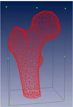
Fig. 1 Sample mesh geometry of the proximal femur generated from CT scan
RESULTS
Previous studies have indicated that strain increases with impaction force, overlap, and bone properties. The results of this study will provide insight into the relative importance of each factor in terms of its contribution to bone strain and fracture.
CONCLUSIONS
Femoral fracture can occur during the insertion of prostheses associated with hip replacement surgery. Past research has focused on the use of cadaveric femora to measure cortex strains. To our knowledge this field has never been studied using the finite element method.
REFERENCES
[1] Dammak M., Shirazi-Adl A., Zukor D.J. Analysis of Cementless Implants using Interface Nonlinear Friction - Experimental and Finite Element Studies. Journal of Biomechanics 30; 2; 1997 p. 121-129.
[2] Elias J.J., et al. Medial Cortex Strain Distribution during Noncemented Total Hip Arthroplasty. Clinical Orthopaedics & Related Research 370; 2000 p. 250-258.
[3] Bessho, Masahiko, et al. Prediction of Strength and Strain of the Proximal Femur by a CT-Based Finite Element Method. Journal of Biomechanics 40; 8; 2007 p. 1745-1753.
CONSTITUTIVE MODEL OF DEFORMATION-INDUCED
DEGRADATION OF POLYMERS
FOR APPLICATION IN BIODEGRADABLE STENT DESIGN
João S. Soares1(*), James E. Moore, Jr.2, and Kumbakonam R. Rajagopal2,3 1
MOX – Dipartimento di Matematica “F. Briochi”, Politecnico di Milano
2
Department of Biomedical Engineering, Texas A&M University
3
Department of Mechanical Engineering, Texas A&M University
(*)Email:
BACKGROUND
Fully biodegradable polymeric stents are thought to be the third revolution in minimally invasive cardiology. After the breakthrough development of percutaneous balloon angioplasty and the dawn of the drug eluting stents era, increasing interest is being brought to temporary implants that fulfill the mission and step away. The concept of biodegradable stents is based on the fact that the role of stenting is temporary and is limited to the intervention and shortly thereafter, until re-endothelialization and healing are obtained. Beyond that, no utility or advantage for stents remaining in place has been demonstrated.
Significant challenges in the development of novel biodegradable stent designs are their difficult manufacturing and the lack of precise engineering modeling tools. Both of these aspects lead to a considerable amount of uncertainty; still, the sophistication of the existing designs has been wide. On the other hand, scant data are available on the mechanical behavior of biodegradable polymers undergoing degradation. Degradable polymers are materials that show complex behavior upon deformation: conformational changes of the network chains, the formation of crystalline structures, and local changes in amount of swelling occur. In addition, hydrolytic scission occurs spontaneously in the presence of readily available water and its rate is influenced by the properties of the molecular network, such as bond availability, steric hindrance, and hydrophilicity, which are often related with the bulk deformation of the network. Furthermore, experiments show that deformation and degradation are coupled processes. A typical stent design strategy is to conduct experiments, starting in vitro, followed by in vivo with animal models, which in turn will lead towards the ultimate goal of successful clinical trials with humans and FDA approval. Computational simulations with biodegradable stents are either non-existent or too simplistic in virtue of the inability to account for the complexity of the constitutive modeling of the biodegradable material.
CONSTITUTIVE MODEL
the kinetic equation governing the degradation process is dependent on a local measure of deformation.
Incorporation of the model into a finite element formulation renders real life applicability in biodegradable stent design with the analysis of real stent geometries. The extendable capabilities of commercially available software packages, such as ABAQUS user subroutines, allow the definition of constitutive models of wide complexity.
For poly(L-lactic acid), subroutine UHYPER was used to define a degradation-dependent hyperelastic-like material of the form ( , ) ( ) (I 3)( 3) ( ) ln[1 ( 3)]
W I d =λ d e− − I− +µ d +a I − , where d is the amount of degradation, I = tr FFT (F is the deformation gradient), λ(d) and (d) are degradation-dependent material properties, and a is a constant. Degradation imparts a decrease in material properties following λ( )d =λ0(1−d) and µ( )d =µ0(1−d), where λ0 and
0 are degraded material constants obtained from uniaxial tensile experiments with
non-degraded poly(L-lactic acid) cylindrical fibers (Soares, 2008).
The equation governing degradation is incorporated through the USRFLD subroutine and is of the form d = −
(
1 d k)
τD, where k = k(I,II) is the deformation-dependent rate (withII = ½ [I 2 – tr (FFT)2]½) and τD the characteristic time of degradation.
IMPLICATIONS IN BIODEGADABLE STENT DESIGN
Several stent geometries were analyzed when subjected to constant outer pressurization. The rate of increase of degradation depends on the deformation to which the material is subjected. Thus, the parts of the stent that experience greater states of strain degrade at a faster pace. Degradation leads to material depreciation and allows stronger deformations in response to the same external loads, which will in turn lead to greater rates of degradation. As this takes place, the stent clearly cedes its ability to withstand the constant outer pressurization. The stent eventually creeps inwards to a significant extent until failure, a programmed event that should not occur before healing is complete.
Degradation is mostly confined to the crowns and the junction points and failure of the material will most likely happen at these places. On the other hand, stent struts and connector bars remain mostly non-degraded because stent deformation is barely felt at these parts; after failure, these could potentially be responsible for dramatic embolic complications downstream. The proposed model could therefore be used to test designs that aim toward a more uniform degradation.
The overall deformation patterns of a stent made of a material that loses its integrity are clearly different when compared with a permanent unchanging counterpart; hence, blind application of permanent stent design concepts is ill suited at inception for biodegradable stent design. The time dependent dynamic aspect of the implant not only must be taken into account at the design stage, but also should be used to interact with the body’s reaction and to enhance healing.
REFERENCES
[1] Rajagopal K.R., Srinivasa A.R., Wineman A.S. On the shear and bending of a degrading polymer beam. International Journal of Plasticity, 23; 9; 2007, p. 1618-1636.
FINITE ELEMENT ANALYSIS OF MICROCRACK LOCALISATION
AND PROPAGATION INSIDE CORTICAL BONE TISSUE
Dieter Kardas(*), and Udo Nackenhorst
Institute of Mechanics and Computational Mechanics, Leibniz Universität Hannover, Germany
(*)Email:
SYNOPSIS
In this contribution an approach will be shown to simulate microcrack initiation and propagation inside cortical bone tissue, by using computational mechanics techniques. Therefore, a micro model of a 3D anisotropic and inhomogeneous lamellar bone section will be introduced. To compute the delamination between bone lamellae patterns, a constitutive model based on continuum damage mechanics and additional localisation theory is used. Numerical computations show good agreement with in vitro measured crack shapes.
INTRODUCTION
Bone tissue is continuously renewed during life. This process is called bone remodeling. It is well accepted, that osteocytes are sensor cells for the remodeling cycle – but what is stimulating these cells is still under discussion. One theory describes a stimulus over a multiple raise of osteocyte deformation or total disruption, as a result of microcracks inside the bone tissue (Martin, 2000).
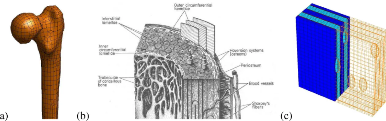
(a) (b) (c)
Fig. 1 Hierarchical structure of bones. a: FEA model of a human femur, b: Section of cortical bone (Martin, 1998), c: FEA micro model of lamellar bone with lacunae;
RESULTS
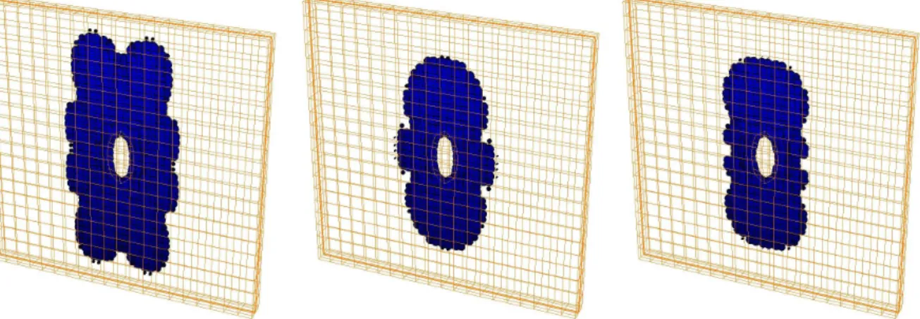
Changes in angular collagen fiber positions result in different crack shapes, crack dimensions, crack initiation points and crack initiation time after physiological loading. Studies on this effect are made with varying angular fiber positions going from 0° to 90° (Fig. 2; results for 20°, 45° and 70°). Boundary conditions of the finite element model are chosen to fit the real environment of the microstructure inside cortical bone. Loads are applied as Diriclet boundary conditions, obtained from a macro model (human femur) computation (Fig. 1, a).
Fig. 2 Microcrack shape for different angular collagen fiber positions (left: ±20°, right: ±45°, right: ±70°);
CONCLUSIONS
The use of formulations for delamination based on continuum damage mechanics and further implementation of crack localisation theory, leads in a new approach for computation of microcracks inside cortical bone.
In vitro measured cracks show an elliptical crack shape (Taylor, 2007). A good agreement is shown in fig. 2 where collagen fibers are at 45°. This leads to an assuption, that the angular fiber position in lamellar bone tissue lies around this value.
Future work on this project, which supports the research work of finding the right stimulus for bone remodelling, is to extend the constitutive model to a discontinuous behavior under dynamic load conditions. Furthermore, the effects on osteocytes themself have to be computed using scale bridging techniques.
REFERENCES
[1] Martin R. B. Towards a unifying theory of bone remodeling. Bone, 26; 2000 p. 1-6.
[2] Matrin R. B., Burr D. B. Sharkey N. A. Skeletal tissue mechanics. 1st edition, Springer Berlin; 1998 p. 32.
[3] Taylor D. Fracture and repair of bone: A multiscale problem. Journal of Material Science, 42; 2007 p. 8911-8918.
[4] Reilly G. C. Observation of microdamage around lacunae in bone. Journal of Biomechanics, 33; 2000 p. 1131-1134.
HUMAN FEMUR ASSESSMENT USING ISOTROPIC AND
ORTHOTROPIC MATERIALS DEPENDENT OF
BONE DENSITY
E.M.M. Fonseca(*), M.J.Lima, and L.M.S. Barreira Polytechnic Institute of Bragança, Portugal
(*)Email:
SYNOPSIS
The bone mass reduction and the deterioration of the tissue micron-architecture lead to a bigger fragility of the bone and to the consequent increase of the fracture risk. For this fact, it is considered excellent the quantification of the mass density and the verification of its influence in the bone resistance assessment. The apparent density is defined as the density without fluid influence, being the effective density at that includes the marrow mass, essentially fluid. This measurement is made through the use of a gray scale values on the medical image in study. The values in Hounsfield units are determined, being this scale later converted into measure of the bone density. With this measure an exponential relation will be used allowing calculate the biomechanics properties dependence for cortical and trabecular bone. With this work it is intended to assessment the susceptible weak zones, for a human femur with 70 years old, using the finite element method through ANSYS® program. The main objective is obtaining the stresses distributions, using different values of bone density and their relation with exponential laws for isotropic and orthotropic materials properties.
INTRODUCTION
The finite element method has been used in biomechanics studies through the simulation of some anatomical structures. Some authors have come to dedicate their works in this area, through numerical simulations of human femur using solid models (Baca, 2008), (Taylor, 1996), for example. Also, in the experimental area, they have been published results from (Bergmann, 2001), (Simões, 2004). Some authors, (Baca, 2008), (Peng, 2006), have used different numerical simulations with isotropic and orthotropic constituent models, for bone tissues. The biomechanics properties depend on structural aspects of the bone, its bone geometry, but also on intrinsic properties of the material, between which, the bone density. Particularly, the bone density keeps one strong inverse relation with the risk of bone fracture (Augat, 2006). The objective of this work is to produce one numerical femur model, constituted of different cortical and trabecular bone layers, through the effective density measurement under medical image. The study will be developed with the previous medical image treatment, gotten of one male femur with 70 years old. Pre-processing and treatment techniques were used for the study of medical image. The femur model is converted into 3D CAD format being later used in a biomechanics numerical simulation.
RESULTS
femur. The inclined plan (i), assigned for ADPPr, belongs to the Previous, Distal, Posterior and Proximal zone femur. A trabecular and cortical solid mesh are also presented.
Fig.1 Mesh of human femur: cortical and trabecular bone.
The results of the equivalent stresses in plan (h) and plan (i) are represented in figure 2. In the Medial femur part the stresses are more raised, being that the influence of the mechanical properties if reflects in the Lateral femur zone.
0 5 10 15 20
1 2 3 4 5
von-Mises Stresses
[MPa]
(IH Isot) (INH1 Isot) (INH2 Isot) (IH Orth) (INH1 Orth) (INH2 Orth) A70 M70 P70 L70 A70
0 5 10 15 20
1 2 3 4 5
von Mises Stresses
[MPa]
(IH Isot) (INH1 Isot) (INH2 Isot) (IH Orth) (INH1 Orth) (INH2 Orth) A70 D70 P70 Pr70 A70
Fig.2 Equivalent stresses in cortical zone (h) and (i).
CONCLUSIONS
The maximum values of stresses in compression were observed in the Medial and Distal zones. The influence of mechanical properties, due different bone density, modifies the numerical results significantly. The values of stresses are lesser in the Posterior zone of femur. The relevance of the mechanical properties use under bone density influence is a greater importance in this study. The results obtained with orthotropic materials, were lesser than when using isotropic properties.
REFERENCES
[1] Baca V., et. al., Comparison of an inhomogeneous orthotropic and isotropic material models used for FE analyses, Medical Engineering & Physics, 30; 2008 pp.924-930.
[2] M.E. Taylor, et. al., Stress and strain distribution within the intact femur: compression or bending?, Medical Engineering Physics, 18; 2; 1996 pp.122-131(10).
[3] G. Bergmann, et. al., Hip contact forces and gait patterns from routine activities, Journal of Biomechanics, 34; 7; 2001 pp. 859-871.
[4] J.A. Simões, et. al., Influence of head constrain and muscle forces on the strain distribution within the intact femur, Medical Engng. and Physics, 22; 7; 2000 pp.453-459. [5] Peng L., Bai J., Zeng X., Zhou Y. Comparison of isotropic and orthotropic material property assignments on femoral finite element models under two loading conditions, Medical Engineering Physics, 28; 2006 pp.227-233.
NUMERICAL SIMULATION OF BLOOD FLOW IN A
STENOTIC ARTERY
Luisa C. Sousa(*), Catarina F. Castro, and Carlos C. António Faculty of Engineering, University of Porto
Rua Dr. Roberto Frias s/n, 4200-465 PORTO, Portugal
(*)Email:
SYNOPSIS
The purpose of this paper is to develop a numerical computational methodology for the simulation of blood flow in a stenotic artery. Steady and pulsatile blood flows are considered. The biochemical and mechanical interactions between blood and vascular tissue are neglected and the flow is considered through a rigid tube. Numerical results for various non-Newtonian models are compared, such as velocity and shear stresses distributions.
INTRODUCTION
In many developed countries, diseases as heart attack or cerebral infarction are top of death causes. Altered flow conditions in blood vessels, due to branching, bifurcations and flow-reversal zones play an important role in the development of arterial diseases. When an atherosclerotic stenosis in a coronary or carotid artery prevents the blood flow, it might cause respectively a heart or a brain attack; otherwise, if the surface of the stenosis is damaged, a fragment of the atherosclerotic plaque or a blood clot can emboli with blood flow and occlude a more distal cerebral artery or coronary artery. Although blood flow is normally laminar, the periodic unsteadiness or pulsatile nature of the flow makes possible the transition to turbulence when the artery diameter decreases and velocities increase.
It is very important to know how blood is flowing in those areas, which could help doctors or surgeons to make a diagnosis or to plan a surgery. In recent years, the development of computational techniques in fluid dynamics together with increasing performances of the hardware, found a promising field of application in the framework of vascular research (Taylor, Hughes, and Zarins, 1998, and Quarteroni, Tuveri and Veneziani, 2003). Due to new technology of medical imaging data acquisition such as computed tomography, angiography or magnetic resonance imaging (MRI), it has become feasible to construct three dimensional models of a blood vessel. Measuring techniques such as Doppler ultrasound have improved to provide accurate information on the flow fields. Therefore, carrying research on shape acquisition together with computational techniques in fluid dynamics is possible and it is important to develop circulatory simulation codes such as blood flow simulation.
MATHEMATICAL MODEL
Due to the complexity of the cardiovascular system, a preliminary analysis aiming suitable simplifying assumptions for the mathematical modelling process is needed (Himeno, 2003).
. p
Dt
∂
ρ + ∇ = −∇ + ∇ +
v
v v T f
where v is the flow velocity, ρ is the fluid density, p is the pressure, Tis the deviatoric stress tensor, and f represents body forces (per unit volume) acting on the fluid. This equation results from the application of the principle of mass conservation. Considering blood flow an incompressible non-Newtonian flow and negleting body forces, the equation of continuity and the Navier-Stokes equations become:
2
. 0
1
. p
t
∇ =
∂ + ∇ = − ∇ + ∇
∂ ρ
v v
v v v v
The upwind-difference method is used for the convective terms and the first order Euler implicit method is used for the time-differencing term.
RESULTS AND CONCLUSIONS
The outcomes will contribute to characterize the physiology of the human circulatory system, to model steady and pulsatile blood flow and detect turbulence caused by changes in flow velocities and vessels diameter.
This study will also allow identify with scientific support the areas that should be altered by reconstruction and revascularization operations leading to correction of form and function in a most effective way.
REFERENCES
[1] Himeno R., Blood Flow Simulation toward Actual Application at Hospital. The 5th Asian Computational Fluid Dynamics, Korea, 2003.
[2] Quarteroni, A., Tuveri, M., Veneziani, A. Computational Vascular Fluid dynamics: problems,models and methods. Computer and Visualization in Science, 2; 2003, p. 163-197.