Henor Artur de Souza
Emeritus Member, ABCM
Francisco de A. das Neves
[email protected]Cristiano C. G. Pereira
[email protected] School of Mine Federal University of Ouro Preto-UFOP 35400-000 Ouro Preto, MG. BrazilUrânia Costa Sales
[email protected] Unicentro Izabela Hendrix da Igreja MetodistaAcoustical Vibration Characterics of
Prefabricated Panels Employed in
Industrialized Construction
With the development of industrialized steel construction, new constructive elements have been brought not only to the market, but to the everyday construction site as well and, in this way professionals and users have questioned their efficiency. In respect to vibrations in floors, what can be detected is that floor structures are thinner and a decrease of the mass in the horizontal closing panels and the utilization of new materials and systems have led them to have lower natural frequencies, and so are nearer to the frequencies produced by walking. This decrease of mass of the closing panels also lead to a considerable weakness in terms of acoustical insulation, which can cause unfavorable conditions and discomfort. Thus, it becomes necessary to do detailed studies of the efficiency of the vibration and acoustical performance of the new systems to obtain the characterization and the qualification parameters in order to optimize their use. This study does a comparative evaluation of some kinds of horizontal and vertical closing systems in respect to the vibrational and acoustical insulation performance.
Keywords: steel construction, prefabricated floors, vibratory performance of floors, acoustic performance of vertical closing panels
Introduction
In Brazil, only after the decade of the 80 a larger demand for commercial and residential constructions in steel started. The technological development for these types of constructions and their presentation were always in second plan, since the culture of concrete has established in this country. This culture has started and is still present due to three basic advantages that concrete can provide: easy to learn, low cost and rapid construction. Reinforced concrete still is the main structural model adopted in the majority of the Brazilian constructions, however, steel is being rediscovered by architects and builders, because it is a system that introduces great potentialities for industrialized constructions, with the possibility of reduction in the process time, wastes and labor, with reductions in cost and excellent results of the process.1
The closing system of the construction is one of the most important stages in the construction process because it is directly linked to the image and to the comfort of any construction. When it is shown that steel constructions can result in cost and waste reduction for the subsystems, like door and window framework, installation and exterior finishing, it becomes desirable to develop an efficient process in steel construction, and necessary to develop complementary systems that work, and are accepted by the users and by the technical community.
Nowadays, in steel construction, the structures are still frequently seen with the use of conventional closing systems of masonry, which is problematic, because the execution time frame of these systems is not suitable, and the systems interfaces are not always adequately solved. The association of steel construction to the conventional masonry structure does not imply the occurrence of incompatibility problems, but if the differences are not considered in specific points during the conception stages, project and construction problems will unfortunately occur.
Since the introduction of industrialized closing panels the use is getting larger and larger in the work sites, though such elements are not always used adequately together with all their potential. It is very common to detect the application of innovative closing components used in traditional ways, which can generate problems to be solved during the construction, and even, future problems for the users of the structure. Actually, ever since its conception, the
right closing systems still need to be found and incorporated to our environment and constructive process (Souza, 1997).
This paper does an acoustical and vibrational analysis of the closing systems for steel structures used in Brazil. Concerning the acoustic analysis, with lighter structures and closing systems with a smaller mass for isolating the environments, a considerable weakness in terms of acoustical insulation has occurred, which can lead to uncomfortable acoustical conditions that are not satisfactory. Having in mind the need to know the real acoustical efficiency of the panels, the objectives were defined as: acoustical characterization of the closing panels, through the determination of the loss of acoustical transmission (LT) according to the different sound frequency levels, and to analyze the degree of acoustical efficiency of the closing panels, relatively to the conventional closing system, and considering the ambient sound transmission. In respect to the vibrations in floors, what can be detected is that floor structures are thinner and a decrease of the mass in the horizontal closing panels and the utilization of new materials have led them to having lower natural frequencies, and in this way are nearer to the frequencies produced by walking. Therefore, the goal is to characterize the kinds of industrialized horizontal closings systems, in respect to vibrations, by doing a comparative study of the performance of each type of closing systems in hypothetical situations pre-defined, according to project procedure.
The response in terms of acceleration for each floor have been obtained by means a transient dynamic analysis, taking into consideration the locations where the vibration level is greatest, normally at those points that have presented the greatest static displacements. By confronting those values of acceleration obtained through numerical simulation with those presented in the graphics based on the base curves, multiplied by parameters as recommended by the International Standard Organization – ISO 2631, it is possible to check if the floor attends the criterion regarding the human comfort.
Closing Panels Evaluated
Vertical Closing
panels of interconnecting cellular concrete, panels of solid concrete, concrete panels with a core of Polyethylene, plates of cement and plasterboard panels.
In addition to these industrialized panels, the evaluation included partitions of conventional masonry of ceramic brick, with the purpose of doing a comparison of the new systems with the conventional construction. For the conventional masonry, it was determined: internal walls with a thickness of 15 cm and superficial density of, M = 270 kg/m2, and external walls with a thickness of 20 cm and superficial density of, M = 360 kg/m2.
Horizontal Closings
The kinds of industrialized floors, chosen for analysis, were determined for their different characteristic among the prefabricated floors and for their potential of utilization in association to steel structure. These floors are described, in a simplified way, in table 2.
In addition to the industrialized floors, indicated in table 2, a concrete slab with an average thickness of 10 cm and the weight of 2,50 kg/m2 molded in location was included in the evaluation.
Acoustical Characterization
To accomplish a comparative study, concerning the acoustical efficiency of the vertical closing systems for steel structure, five kinds of panels were chosen (table 1) and an inventory of their characteristics was done. From the characteristics of the panels and in consideration of some assembling variations, the values of the loss of acoustical transmission (LT) in function of the incidence frequency of the sound (f) for each panel were determined. These calculations were done in the frequency spectrum from 125 to 4000 Hz, based on the formulas to follow.
Table 1.Panels used for external closing.
Panels Behavior Thickness D (m) Superficial Density M
(kg/m2)
0,10 (plate) 75,00
Cellular
concrete Simple wall
0,15 (plate) 112,50
0,09 (plate) 207,00
Solid
concrete Simple wall
0,14 (plate) 322,00
0,01 (plate) 13,30
Simple wall
0,015 (plate) 19,95
0,01 (plate) 13,30
Cement plate
Double wall
(Cement plate + Plasterboard – d= 7,5 cm – ar)
0,015 (plate) 19,95
0,09 (unit) 139,00
Simple wall
0,14 (unit) 138,00
Concrete + Polyethylene
Double wall(d= 3 e 8 cm –Polyethylene) 0,03 (concerto) 0,09 (unit) 69 (concrete)
Plasterboard Double wall(d= 4,8 e 7,5 cm – ar)
0,012 (Plasterboard) 0,10 (unit)
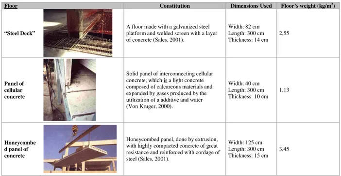
Table 2. Characterization of the evaluated horizontal closings.
Floor Constitution Dimensions Used Floor’s weight (kg/m2)
“Steel Deck”
A floor made with a galvanized steel platform and welded screen with a layer of concrete (Sales, 2001).
Width: 82 cm Length: 300 cm Thickness: 14 cm
2,55
Panel of cellular concrete
Solid panel of interconnecting cellular concrete, which is a light concrete composed of calcareous materials and expanded by gases produced by the utilization of a additive and water (Von Kruger, 2000).
Width: 40 cm Length: 300 cm Thickness: 10 cm
1,13
Honeycombe d panel of concrete
Honeycombed panel, done by extrusion, with highly compacted concrete of great resistance and reinforced with cordage of steel (Sales, 2001).
Width: 125 cm Length: 300 cm Thickness: 15 cm
3,45
For the calculation of the loss values of acoustical transmission (LT), in a simple break down, it used the Law of mass, formula shown by Gerges (1992):
(
Mf)
,( )
dB logLT=20 −474 (1)
where LT= transmission loss; M = superficial density and f = frequency. For the calculation of the loss of acoustical transmission (LT), in double walls, it used an adaptation of the Law of mass (Gerges, 1992), according to the following calculation:
( )
dB , cd sen log ,
LT LT
LT 1 2 60 20 2 −474
+ + +
= π (2)
Where LT = loss of acoustical transmission; LT1 = loss of acoustical transmission of point 1; LT2 = loss of acoustical transmission of point 2; d = distance between point 1 and 2 (thickness of point 3) and c = speed of the sound in the point that separates the point 1 and 2 (at point 3).
With the goal of comparing the results obtained analytically, through the equations 1 and 2, data collected from literature was inserted: the data refer to experiments done with walls similar to the walls evaluated in this paper and a formula developed by Silva (2000) was used.
(
Mf)
,( )
dB log,
LT=143 −292 (3)
For analysis of results obtained by the simplified formulas represented by equations 1, 2 and 3, values of LT from experimental studies found in literature were inserted in the graphs (Fig. 1 to the Fig. 7).
Panels for External Closings
Panels of Interconnecting Cellular Concrete
The panel evaluated (Fig. 1), consists of a simple plate fastened to a steel frame and the final exterior finishing of the wall was not considered in the evaluation. According to illustration 1, the curves obtained by the law of mass resulting in high values of LT were noticed, if compared with the results of formulation developed by Silva (2000). However, in all the curves, the panels of cellular concrete showed lower values of lost transmission than the values shown by the conventional masonry.
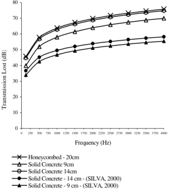
Panels of Solid Concrete
The panel evaluated in Fig. 2 consists of a simple plate with a thickness of 9 cm or 14 cm, the final exterior finishing of the internal wall was not considered in the evaluation. The concrete panels, analyzed with the shown dimensions at issue, exhibit a lower performance than the conventional masonry. The Silva’s formulation (2000) supplies values for the transmission loss (LT), much lower than those obtained by the law of mass.
0 10 20 30 40 50 60 70 80
0 250 500 750 1000 1250 1500 1750 2000 2250 2500 2750 3000 3250 3500 3750 4000
Frequency (Hz)
T
ra
n
sm
is
si
o
n
L
o
st
(
d
B
)
Cellular Concrete - 10cm Honeycombed -15cm
Honeycombed -20cm Cellular Concrete - 15cm
Cellular Concrete - 10 cm - (SILVA, 2000) Cellular Concrete - 15 cm - (SILVA, 2000)
0 10 20 30 40 50 60 70 80
0 250 500 750 1000 1250 1500 1750 2000 2250 2500 2750 3000 3250 3500 3750 4000
Frequency (Hz)
T
ran
sm
issi
o
n
Lo
st
(d
B)
Honeycombed - 20cm Solid Concrete 9cm Solid Concrete 14cm
Solid Concrete - 14 cm - (SILVA, 2000) Solid Concrete - 9 cm - (SILVA, 2000)
Figure 2. LT variation for panel of solid concrete.
Concrete Panels with a Core of Polyethylene
The panel, evaluated in Fig. 3 consists of a plate formed by three layers, being the first and the last one of reinforced concrete and the intermediary of expanded polyethylene; the final exterior finishing of the internal wall was not considered in the evaluation.
0 20 40 60 80 100 120 140
0 250 500 750 1000 1250 1500 1750 2000 2250 2500 2750 3000 3250 3500 3750 4000
Frequency (Hz)
T
ra
ns
m
is
si
on
L
os
t (
d
B)
Honeycombed - 20cm
Concrete + polyethylene - 9cm - double sided Concrete + polyethylene - 14cm - double sided Solid Concrete - 9cm
Concrete + polyethylene - 9 cm - one sided Concrete + polyethylene - 9 cm - (SILVA, 2000) Experimental - Conc.+polyet. - 10 cm - (SILVA, 2000)
Figure 3. LT variation for concrete panel with a core of Polyethylene.
As introduced in Fig. 3, the concrete panel with a core of polyethylene was evaluated as a simple wall by the Eq. (1) and (3), exhibiting results lower than the masonry and as a double wall, by
masonry. Observe the results obtained by Silva (2000), for similar panel in experiments and through its formulation, the excessive values given by the law of mass are shown.
Panels in Cement plate
The panel, evaluated in Fig. 4, consists of only one plate with the thickness values of 1,0 cm and 1,5 cm, the final exterior finishing of the wall was not considered in the evaluation. As shown in illustration 4, the panels in Cement plate exhibit acoustical performance inferior to the conventional masonry. However, it should be stressed that this kind of closing is, generally mounted, in association with some kind of panel placed internally in the construction that creates a double wall with a cavity of intermediary air. In this way, the acoustic performance evaluated, according to equation 2, acquires an improvement; considering its as a double wall, with one side in cement plates and the other side in plasterboard, and both sides being separated by an air cavity of 7,5 cm. In this evaluation, an exacerbation of values in regards to plotting the LT curves (Sales, 2001).
0 20 40 60 80 100 120
0 250 500 750 1000 1250 1500 1750 2000 2250 2500 2750 3000 3250 3500 3750 4000
Frequency (Hz)
T
ran
smi
ssi
o
n
Lo
st
(
d
B)
Honeycombed - 20cm Cement Plate - 1cm Cement Plate - 1,5cm
Cement Plate - 1 cm - (SILVA, 2000) Cement Plate - 1,5 cm - (SILVA, 2000) Cement Plate 1 cm c/ pl. de gesso
Figure 4. LT variation for panel of Cement plate.
Panels for Internal Closings
Plasterboard Panels
0 10 20 30 40 50 60 70 80 90 100
0 250 500 750 1000 1250 1500 1750 2000 2250 2500 2750 3000 3250 3500 3750 4000
Frequency (Hz)
T
ra
ns
m
is
si
on L
o
st
(
d
B)
Plaster board (PREGYPLAC) d=7,5 cm Honeycombed -15cm
Experimental - plaster - d=7,5 cm - (BARING, 2000) Experimental - plaster - d=4,8 cm - (SILVA, 2000) Plaster board (PREGYPLAC) d=4,8cm
Figure 5. LT variation for plasterboard panels.
Analysis of the Results
The external solid concrete interconnecting Panels with a core of Polyethylene and cellular concrete presents a lower performance acoustically than the conventional masonry, when evaluated as simple plates and with the thick nesses in question. This experiment is confirmed by the formula developed by Silva (2000). On the other hand, through this formula used for double panels, results for the same concrete panels with a Polyethylene core, superior to the performance calculated for conventional masonry, (Fig. 6) have been obtained.
0 2 0 4 0 6 0 8 0 10 0 12 0 14 0
0 2 5 0 5 0 0 7 5 0 10 0 0 12 5 0 15 0 0 17 5 0 2 0 0 0 2 2 5 0 2 5 0 0 2 7 5 0 3 0 0 0 3 2 5 0 3 5 0 0 3 7 5 0 4 0 0 0 Frequency (Hz)
Honeycombed - 20cm Cellular Concrete Panel - 10cm Cement Plate - 1cm
Solid Concrete Panel - 9cm
Concrete + polyethylene - 9cm - como pn. d Concrete + polyethylene - 9 cm - como pn.
Figure 6. LT variation for external closing panels.
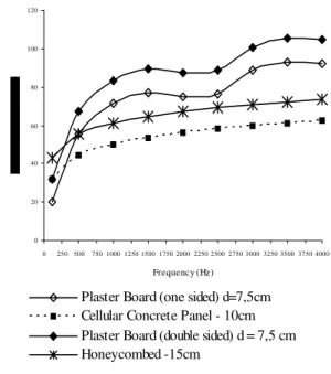
According to equation 01 used on the internal interconnecting panels of cellular concrete presents a lower acoustical performance than the conventional masonry. What is confirmed by the formula developed by Silva (2000). Through the equation 02, used on the partitions with double panels, of plasterboard obtains results
shown in Fig. 7. This can be considered an excessive value, if the experimental results, shown in Fig. 5, are taken into account.
The industrialized panels analyzed as Separate plates by the law of mass, showed lower loss of transmission values than the conventional masonry, which was evaluated by the same method. On the other hand the panels analyzed as double panels, when compared to the values of sound insulate in masonry, showed results superior to those panels. This should be taken as an overestimation and not consisted with the real behavior, which can be verified through experimental data collected in literature.
0 20 40 60 80 100 120
0 250500 750 1000 1250 1500 1750 2000 2250 2500 2750 3000 3250 3500 3750 4000
Frequency (Hz)
Plaster Board (one sided) d=7,5cm Cellular Concrete Panel - 10cm Plaster Board (double sided) d = 7,5 cm Honeycombed -15cm
Figure 7. LT variation for panels of internal closing.
The acoustic performance of the conventional masonry still shows a superiority to the majority of the systems of industrialized closings, however there are some systems that offer results very close to the conventional masonry, like the panels of solid concrete and the concrete Panels with a core of Polyethylene. That performance is reaffirmed, since it was not taken into account any kind of internal finishing for these panels, which in most cases receive a metallic frame and plasterboard on the internal side, what would increase their insulation capacity.
The internal closing systems that show the worst results of transmission loss were the interconnecting panels of cellular concrete. However, the comparison of these results, with the values obtained for the partitions of plasterboard, are not reliable, since the evaluations were done with different formulas (Eq. (1) and (2)). By means of experimental results found in literature, the performance of the plasterboard partitions can be classified as satisfactory, compared to the conventional masonry. The performance
The external panels that show the smallest degree acoustical insulation were the Cement plates, followed by the interconnecting panels of cellular concrete. It can be said that the last two have the worst results, since with them it is not common to construct a false internal walls in plasterboard that is common with the Cement plates. The utilization of these false walls creates an air cavity and a new shield for the sound that clearly improves the capacity of the acoustical insulation.
Vibratory Characterization
excitement action in the floor and acceptable limits of vibration (Rainer et al., 1988). In that way, the study here accomplished proposes a vibratory evaluation, through numeric simulation. Such evaluation takes into account pedestrians walking as excitement source, the characteristics of four types of floors structured in steel and the criteria of minimum comfort recommended by standard, for four hypothetical structural situations.
The Dynamic Problem of Vibration of Floors
For the description and characterization of the dynamic problem, involving vibrations of floors, it is important that are appraised the characteristics of each floor, as their outline conditions, mass, natural frequency, rigidity and capacity of reduction; as for the characteristics of the excitement loads, as their variability with the time, their excitement frequency and their magnitude; and as for the acceptability level and human perception, in terms of factors of answer lifted up statistically.
In this work only the dynamic load is considered generated on the floors by human activities. The load induced in the floors of the constructions due to the human activities as running, to jump, to dance and to walk, mainly this last one, it can be faced as being a load with characteristics of the harmonic and impulsive load.
The load in function of the time for activities that involve human activities, how to walk, to jump, to run and to dance, it can be described through a series of Fourier of harmonic n, given by the Eq. (4) (Vasconcelos, 1998),
(
T i)
i n
i
st Gst sen i f t
G ) t (
F = + ⋅α ⋅ π⋅ ⋅ ⋅ −φ
=
∑
21
(4)
where Gst is the load density (forces for unit of area); fT is the
frequency of excitement of the force (fundamental frequency of the human activity); φi is the relative phase of the excitement force and αi are the coefficients of the series. In the people's case walking on
the floor and considering important just the harmonic first three for the description of the force, it is obtained for Gst = 700 N/m2 (weigh
of a person); α1 = 0.4; α2 = 0.1; α3 = 0.1; i = 1, 2 e 3; ft = 2 HZ
(adopted); range of fundamental frequency for people walking among 1.6 to 2.4 Hz and φ1 = 0; φ2 = π/2; φ3 = π/2, Eq. (5):
( )
[
]
− ⋅ + − ⋅ + ⋅ + = 2 12 70 2 8 70 4 28070 sen πt sen πt π sen πt π
) t (
F (5)
Analysis Method
The evaluation of the performance of the floor in relation to the vibration criterion for industrialized floors used in the steel structure building is accomplished through the computational simulation using Ansys (ANSYS, 2001). Three hypothetical situations of different arrangements (structuring) of floors they are evaluated. The dimensions of the chosen spans for the floors are close of those dimensions more commonly found at the market.
For the description of the finite element model, it was used two types of elements for all of the computational simulations accomplished. An element of spatial frame was used for the beams, described by Ansys as BEAM4, and a plate element, referred as SHELL63. The element BEAM4 is a unidirectional element constituted by two nodes. The element has six degrees of freedom for node: three translations in the X, Y and Z directions and three rotations around the X, Y and Z axes.
The element formulation takes into consideration hardening tensions and large deformations. The element SHELL63 is a shell
freedom for node: three translations in the X, Y and Z directions and three rotations around the X, Y and Z axes. For the element SHELL63 is possible to enter with normal and parallel loading to the plan, besides the consideration of hardening tensions and large deformations.
With the objective of evaluating which the predominant frequency of vibration for the floors, a harmonic analysis was accomplished in order to verify the importance of the vibrations mode shape in the dynamic response of the structure and to facilitate in the process of the establishment of the modal damping ratio to accomplish the transient analyses. For all of the accomplished transient analyses, the function of descriptive load of human activities was used. The accomplishment of the transient analysis seeks the determination of the values of displacements and nodal accelerations for those nodal points of the floor that presented the largest static displacements.
Once computed the accelerations, in terms of their peak values, the root mean square (r.m.s) values of acceleration equivalent to those peak values are computed, in order to using Standard's prescriptions. In this work, the base curves presented in International Standard ISO 2631:1985 multiplied by a weighted factor has been used, in agreement with the destination of the floor, and as having suggested by Standard. The root mean square values and the values of peak of the acceleration are obtained through Eq. (6),
Λ
Γ rms
m a
a = ⋅ (6)
where, am is the maximum peak of acceleration; arms is the root mean
square and it represents the acceptable value of the acceleration
obtained through the curves of ISO; Γ is the constant that depends
on the analyzed case, being defined for each limit as: = 1/3–it limits I; = 1–it limits II; = 2 - it limits III. The constant, Λ, used for conversion between the RMS value and the peak value, considering
a simple harmonic, it is given by Λ = 2 / 2.
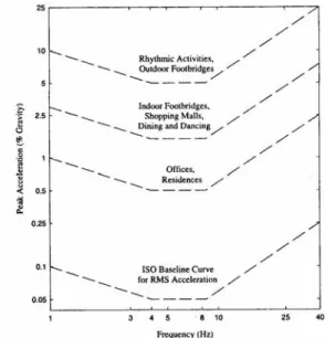
The curves of peak of acceleration to frequency induced in the floor by human activity are shown in Fig. 8. For those situations in which the points representing the computed acceleration are located above certain values of a given limit curve implies that the environment (place) are not attending the comfort criterion.
International Standard ISO 2631:1985 defines the range of parameters of human comfort in three boundaries concerning to human sensation, the exposure time and level of acceleration for which a person may be exposed: Limit I – Limit of the reduced comfort – it is related with the level of vertical acceleration from which the people are annoyed by the vibration, having more difficulties to execute tasks that demand certain concentration, such as eating, to read and to write. Limit II – Limit of fatigue-decreased proficiency – it specifies the boundary beyond which exposure during a long period to vibration can bring a significant risk of impaired working efficiency in many kinds of tasks, particularly those in which time-dependent effects, fatigue, are known to worsen performance. The limit associated to the fatigue-decreased proficiency is defined by ISO 2631:1985 as being three times larger than the limit associated to the reduced comfort. Limit III – Limit of exposure time – is the limit in terms of values of maximum acceleration that a person can be exposed in a safe way, for any frequency condition, duration and direction, in a such way that their limit values are obtaining by doubling the values allowed according to the criterion of to the fatigue-decreased proficiency.
The Analyzed Situations
All structural situations were analyzed as concrete slab molded in site, being considered a medium thickness of 10 cm, specific mass of the concrete and steel of 2500 kg/m3 and 7850 kg/m3 respectively, concrete and steel Young module of 29 GPa and 210 GPa respectively and coefficient of Poisson equal to 0,20 for both materials.
For each structural situation, three types of prefabricated floors were analyzed (“Steel deck”, panels of concrete cellular autoclaved and alveolar panels of concrete extruded) besides the concrete slab molded in site, with the objective of comparing the performance of the prefabricated systems with the conventional ones.
The definition of dimensions of steel cross section, for each situation, was done starting from a previous basic proportioning, considering the most robust cross section to be adopted as pattern, for the four floor types studied. Starting from the minimum dimensions of steel cross section initially chosen, their characteristics could be varied in order to observes the influence degree for each studied floor assembly (Sales, 2001).
Situation 01
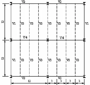
A floor of 18,00 m x 12,00 m, with the spacing between beams of 3,00 m and the outline terms as indicated in Fig. 9. According to the pre-Measurement, the minimum dimensions of the beams are: V1 – external beam (profile 350x38), V2 – external beam (profile 350x38), V3 – internal beam (profile 400x78).
Figure 9. Schematic plant of the floor beams - situations 01 (measured in m).
Situation 02
A floor of 24,00 m x 12,00 m, with spacing between the beams of 3,00 m and outline terms as indicated in the Fig.10. According to pre-Measurement, the minimum dimensions of the beams are: V1 – external beam (profile 200x19), V2 – external beam (profile 400x68), V3 – internal beam (profile 250x27), V4 – internal beam (profile 550x100).
Figure 10. Schematic plant of the floor beams -situation 02 (measured in m).
Situation 03
A floor of 24,00 m x 24,00 m, with spacing between the beams of 3,00 m and outline terms as indicated in the Fig. 11.
Figure 11. Schematic plant of the floor beams - situations 03 (measured in m).
According to pre-measurement, the minimum dimensions of the beams are: V1 – external beam (profile 200x19), V2 – external beam (profile 600x95), V3 – internal beam (profile 250x27), V4 – internal beam (profile 650x155).
With the objective of determining the modal contribution in the response of the floor, i.e., those mode shapes that contribute in an effective way to structural response, in order to verify the susceptibility of the floor related to resonance due to the load induced by people walking, a harmonic analysis was carried out. In this analysis, a force of the type F(t) = F0 sen (t) was applied, with
the force amplitude, F0 = 1000N, and making her to oscillate in a
analysis. In Figs. 12, 13 and 14 are showed the nodal displacements amplitude in function of frequency of the force F(t).
Figure 12. Nodal displacement in function of frequency (Harmonic analysis) – Situation 01.
Figure 13. Nodal displacement in function of frequency (Harmonic analysis) – Situation 02.
Figure 14. Nodal displacement in function of frequency (Harmonic analysis) – Situation 03.
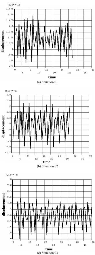
Through a transient analysis, the nodal displacements and accelerations for those points of the floor that presented the largest static displacements were computed, as seen before. In Figs. 15 and 16 are presented the displacements and accelerations computed for each analyzed floor configuration.
(a) Situation 01
(b) Situation 02
(a) Situation 01
(b) Situation 02
(c) Situation 03
Figure 16. Time response of acceleration.
In table (3), the values of the accelerations obtained for the three situations of floors analyzed are presented. A dynamic load given by Eq. (5) was applied and it was considered an oscillation frequency around 2 Hz. The value of RMS acceleration was obtained through Eq. (6).
Table 3. Values of accelerations for the configurations of floors analyzed.
Acceleration (m/s2) Situation 01 Situation 02 Situation 03
amax. 4,75 x 10⁻² 2,03 x 10⁻² 2,31 x 10⁻²
aRMS (Limit I) 1,01 x 10⁻¹ 4,31 x 10⁻² 4,90 x 10⁻²
aRMS (Limit II) 3,36 x 10⁻² 1,44 x 10⁻² 1,63 x 10⁻²
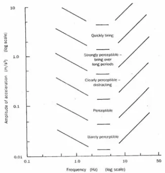
The values of table (3) are compared with the curves shown in the Fig. (17). Because the wide range of frequency to be covered is large, it is common to plot contours indicating human reaction on logarithmic scales of frequency and amplitude of response. This structural response can be expressed in terms of displacements, velocity or acceleration (Fig. (17)).
It is verified that the floor of situation 01 is adapted for the use as residence and office, just when is considered the limit II. On the other hand, the floors of situations 2 and 3 are adapted for the use as residence and office as much for Limit I as for the Limit II.
Figure 17. Qualitative description of human reaction to sustained steady oscillation. SOURCE: Ohlsson, 1982.
Conclusions
The simplified procedure, used here as a method of evaluation the acoustical performance of the prefabricated panels, introduces many limitations for the analyzing situations and requires a parallel experimental verification and/or a numeric study, so that the real terms be considered. However the obtained results are not final evaluations, but are, estimate for a preliminary analysis.
The obtained results, for the vibratory behavior of the floors, through numerical simulation, were shown coherent when compared to those presented by Standard. This proves that this calculation procedure is a good tool to check the condition of comfort of floors in relation to the vibration even in the early project phase.
The human reaction at the vibration levels is substantially psychological; depending partially on the activity that is being carried out. That reaction is usually affected by other incentives, as the sound. Although the vibration level in floors can induce some people to an insecurity sensation, in most of the cases, that doesn't mean that some risk of structural collapse exists (SCI, 1989; Sales et al, 2001).
necessary to carry in count the execution and mounting details of each system and her interferences and interlinking with the surrounding (Sales et al., 2001).
The variables that influence most in the behavior of the floor, regarding the vibration, are the quantity of mass use effectively in the process and the rigidity of the beam structure, mostly of the internal beams of the floor. For the outlet of the values of these parameters, other factors that enter are the dimensions and disposition of the floor and the relative flexibility of the structure at issue
For validation and possible adjustment of the procedure, at issue, it is necessary to do a parallel study or an experimental simulation for the different proposed floors (Sales et al., 2002).
References
ANSYS 6.0, 2001, “User’s Manual”, version 6.0, SAS IP Inc., Canonburg, PA.
Baring, J. G. de A., 2000, “The quality of the buildings and the contribution of the walls of plasterboard”. (In Portuguese), Techné, nº 47 (jully/august), pp.69-73.
Gerges, Samir N. Y., 1992, “Noise: fundamental concepts and control”.
(In Portuguese), Ed. UFSC, Florianópolis, Brazil, 600p.
International Standards Organization, ISO 2631, 1985, “Guide to the Evaluation of Human Exposure to Whole Body Vibration”.
Ohlsson, S. U., 1982, “Floor Vibrations and Human Disconfort”, Department of Structural Engineering, Chalmers University of Technology, Göteborg, Sweden.
Rainer, J. H., Pernica, G., Allen, D. E., 1988, “Dynamic Loading and Response of Footbridges”. Canadian Journal of Civil Engineering, v. 15: pp. 66-71, feb, 1988.
Sales, U. C., 2001, “Analysis of the problems generated in the association between closing systems and metallic structure and acoustic and vibratory characterization of closing panels”. (In Portuguese), Thesis, Federal University of Ouro Preto, Ouro Preto, MG, Brazil, 249p.
Sales, U. C.; Souza, H. A.; Neves, F. A., 2002, “Characterization of the Brazilian Steel Construction and Acoustic Evaluation of Closing Prefabricated Panels”. (In Portuguese), Proceedings of the IX National Meeting of Technology of the Built Environment, Foz do Iguaçu, PR, Brazil, vol. 1, pp. 1-10.
Sales, U. C.; Souza, H. A.; Neves, F. A., 2001, “Interfaces among closing panels and steel structures: real problems”. (In Portuguese), Téchne, São Paulo, vol. aug, n. 53, pp. 98-102.
Sales, U.C., Souza, H.A., Neves, F. A., 2001, “Comparative evaluation of the vibratory acting of prefabricated floors for steel construction”. (In Portuguese), Proceedings of the IV International Congress – The use of steel structures in the building site and I International Congress of Steel Construction, São Paulo, Brazil.
SCI, 1989, “Design Guide on the Vibration Floors” The Steel Construction Institute, SCI-P-0761989, 43p., London.
SILVA, D. T., 2000, “Study of the acoustical insulation in walls and partitions of several natures”. (In Portuguese), Thesis, Federal University of Santa Maria, RS, Brazil, 126p.
SOUZA, U. E. L., 1997, “Quality and productivity in the methods, processes and constructive systems”. (In Portuguese), Proceedings of the Symposium of Research of The Polytechnic School of São Paulo, São Paulo, Brazil.
VASCONCELOS, R. P., 1998, “Reductions of Vibrations in Floor in Reinforced Concrete”. (In Portuguese), Thesis, Federal University of Rio de Janeiro, Rio de Janeiro, RJ, Brazil.