UNIVERSIDADE DA BEIRA INTERIOR
Engenharia
Mission-Based Multidisciplinary Design
Optimization Methodologies for Unmanned Aerial
Vehicles with Morphing Technologies
Pedro Filipe Godinho Lopes Fernandes de Albuquerque
Tese para obtenção do Grau de Doutor em
Engenharia Aeronáutica
(3º ciclo de estudos)
Orientador: Prof. Doutor Pedro Vieira Gamboa
Co-orientador: Prof. Doutor Miguel Ângelo Silvestre
Abstract
One of the most challenging aspects of aircraft design is to synthesize the mutual inter-actions among disciplines in order to achieve enhanced design solutions from the earliest stages of the design process. The complexity of the aircraft physics and the multiple couplings be-tween disciplines complicates this task. The advance of design tools and optimization methods alongside with the computer’s exponential increase in data handling capacity is paving the way for the development of comprehensive multidisciplinary design codes that gradually contribute to a paradigm change, leading to a revolution in the design methodologies.
The research work presented in this thesis features two unmanned aerial vehicles prelim-inary design optimization methodologies - a Parametric Design Analysis and a Multilevel Design Optimization. A specific code has been developed for each methodology, with low-fidelity mod-els being used for the main design disciplines, namely the aerodynamics, propulsion, weight, static stability and dynamic stability. To increase the usability of the codes a graphical user interface for both programs has also been developed.
The first methodology is called Parametric AiRcRaft design OpTimization (PARROT) and relies on a parametric study that optimizes the wing layout for one of two different goals: surveillance mission or maximum payload. Whereas in the former the goal is to maximize the flight range or endurance, the latter’s objective is to maximize the useful payload lifted. Con-straints include the take-off distance, climb rate, bank angle, cruise velocity, among others. The results have shown to be in line with some experimental benchmarking data and to allow the user to easily evaluate the impact of varying two key design variables (wing mean chord and wingspan) on multiple performance metrics, thus significantly contributing to help the de-signer’s decision-making process.
The second methodology is called MulTidisciplinary design OPtimization (MTOP) and adopts the Enhanced Collaborative Optimization (ECO) architecture, together with a gradient-based optimization algorithm. As the goal is to minimize the energy consumption for the specified mission profile, it results in an unconstrained system problem which aims to assure compatibil-ity between subspaces and dully constrained subspace level problems, which aims to minimize the energy consumption. Instead of each subspace representing the traditional design disci-plines (e.g. aerodynamics, structures, stability, etc), the author has chosen to make a different subspace out of each flight stage (e.g. take-off, climb, cruise, etc). The main reason for this choice was the inclusion of morphing technologies as part of the optimization process, namely a variable span wing (VSW), a variable camber flap (VCF) and a variable propeller pitch (VPP). The software final output is the combination of design variables that better suits the objective function subjected to the design constraints. The results have shown how the selection of the optimum combination of morphing/adaptive technologies highly depends on the mission profile. Moreover, the morphing mechanisms weight has a strong impact on the overall performance, which is not easily grasped without an optimization methodology like the one presented.
Globally, these two methodologies foster a more efficient and effective preliminary design stage by feeding the designer’s decision-making process with a large set of relevant data.
Keywords
Multidisciplinary, Multilevel, Parametric, Design, Optimization, Morphing, Unmanned Aerial Vehicle, Mission-based
Resumo
Um dos aspetos mais desafiantes do projeto de aeronaves é a gestão das múltiplas in-terações entre disciplinas, com vista à obtenção de soluções de projeto otimizadas desde os primeiros estágios do projeto de aeronaves. A complexidade da física aeronáutica e os múltiplos acoplamentos entre disciplinas complicam esta tarefa. Com o desenvolvimento de ferramen-tas de projeto e metodologias de otimização aliadas ao aumento exponencial da capacidade de processamento dos computadores e o desenvolvimento de abrangentes códigos de otimiza-ção multidisciplinar estão a contribuir para uma mudança de paradigma, que se espera vir a revolucionar os atuais processos de projeto aeronáutico.
Esta investigação inclui duas metodologias de otimização de projeto preliminar de veículos aéreos não-tripulados - uma otimização paramétrica e uma otimização multinível. Foi desen-volvido um código para cada metodologia, tendo sido utilizados modelos de baixa-fidelidade para as várias disciplinas de projeto, nomeadamente aerodinâmica, propulsão, peso, estabili-dade estática e dinâmica. Para aumentar o leque de utilizadores, foi desenvolvido um interface gráfico para ambos os programas.
A primeira metodologia denomina-se Parametric AiRcRaft design OpTimization (PARROT) e segue uma abordagem paramétrica que otimiza a geometria da asa para um de dois objetivos: missão de vigilância ou máximo peso. Enquanto na primeira o objetivo passa por otimizar o alcance ou autonomia, na segunda o foco passa por maximizar o peso útil sustentado. Con-strangimentos incluem a distância de descolagem, a velocidade de subida, o ângulo de pran-chamento, a velocidade cruzeiro, entre outros. Os resultados mostraram estar em linha com resultados experimentais de referência e ainda permitir ao utilizador avaliar o impacto da vari-ação de duas variáveis-chave (corda média aerodinâmica e envergadura) em diversas métricas de desempenho, desta forma contribuindo significativamente para auxiliar o processo decisório do engenheiro de projeto.
A segunda metodologia chama-se MulTidisciplinary design OPtimization (MTOP) e adota a arquitetura Enhanced Collaborative Optimization (ECO), juntamente com um algoritmo de otimização do tipo gradiente. Uma vez que o objetivo passa por minimizar a energia sumida para um perfil de missão específico, cinge-se a um problema de otimização não con-strangido ao nível do sistema, a solução do qual visa a compatibilidade entre subespaços, e um problema devidamente constrangido com o objetivo de minimizar a energia consumida ao nível dos subespaços. Ao invés de cada subespaço representar as disciplinas tradicionais de projeto (e.g. aerodinâmica, estruturas, estabilidade, etc), o autor decidiu criar um subespaço diferente para cada estágio da missão (e.g. descolagem, subida, cruzeiro, etc). A principal razão para esta escolha foi a inclusão de metodologias adaptativas como parte do processo de otimização, nomeadamente uma asa de envergadura variável (VSW), um perfil alar com curvatura variável através de um flap (VCF) e um hélice de passo variável (VPP). O resultado final é a combinação de variáveis que melhor se adequa à função objetivo, sujeitos aos constrangimentos de projeto. Os resultados mostraram que a seleção da combinação de tecnologias adaptativas adequada está altamente dependente do tipo de missão. Além disso, o peso das tecnologias adaptativas tem um elevado impacto que não é facilmente percecionado sem uma metodologia de otimização como a que é apresentada.
efi-caz e eficiente, alimentando a tomada de decisão do projetista com muita informação rele-vante.
Palavras-chave
Multidisciplinar, Multinível, Paramétrico, Projeto, Optimização, Tecnologias adaptativas, Veículo Aéreo Não-tripulado, Missão
Contents
Abstract v
Resumo vii
List of Figures xv
List of Tables xvii
Acknowledgements xix
1 Introduction 1
1.1 Background and Motivation . . . 1
1.1.1 Greater Research Project . . . 2
1.2 Aircraft Design . . . 2
1.2.1 Conceptual Design . . . 4
1.2.2 Preliminary Design . . . 4
1.2.3 Detailed Design . . . 4
1.2.4 Design Optimization Programs . . . 5
1.2.4.1 Work Scope . . . 7
1.3 Objectives . . . 7
1.4 Contributions . . . 7
1.5 Thesis Structure . . . 8
2 State-of-the-art Review 9 2.1 Multidisciplinary Design Optimization . . . 9
2.1.1 Introduction to Numerical Optimization Concepts . . . 10
2.1.2 Monolithic Optimization Architectures . . . 11
2.1.2.1 Simultaneous Analysis and Design (SAND) . . . 12
2.1.2.2 Individual Design Feasible (IDF) . . . 13
2.1.2.3 Multidisciplinary Feasible (MDF) . . . 13
2.1.3 Distributed Optimization Architectures . . . 14
2.1.3.1 Concurrent Subspace Optimization (CSSO) . . . 14
2.1.3.2 Analytical Targeting Cascading (ATC) . . . 15
2.1.3.3 Collaborative Optimization (CO) . . . 16
2.1.3.4 Enhanced Collaborative Optimization (ECO) . . . 17
2.1.3.5 Bi-level Integrated System Synthesis (BLISS) . . . 18
2.1.3.6 Bi-level Integrated System Synthesis-2000 (BLISS-2000) . . . 18
2.1.3.7 Exact and Inexact Penalty Decomposition (EPD and IPD) . . . 19
2.1.3.8 MDO of Independent Subspaces (MDOIS) . . . 20
2.1.3.9 Quasiseparable Decomposition (QSD) . . . 21
2.1.3.10 Asymmetric Subspace Optimization (ASO) . . . 21
2.1.4 Remarks . . . 22
2.2 Optimization Algorithms . . . 24
2.2.1 Gradient-Based Algorithms . . . 25
2.3 Morphing Technologies . . . 27 2.3.1 Airfoil Morphing . . . 28 2.3.2 Planform Morphing . . . 29 2.3.3 Out-of-plane Morphing . . . 30 2.3.4 Propulsion Morphing . . . 31 2.3.5 Combinations of Morphing . . . 31 3 Analysis Models 33 3.1 Introduction . . . 33 3.2 Programming Languages . . . 33 3.3 Disciplinary Analyses . . . 34 3.3.1 Aerodynamics . . . 34 3.3.1.1 2D Aerodynamic Coefficients . . . 35 3.3.1.2 3D Aerodynamic Coefficients . . . 36 3.3.2 Propulsion . . . 39 3.3.2.1 Electric Motor . . . 40 3.3.2.2 Combustion Engine . . . 44 3.3.2.3 Propeller Model . . . 46 3.3.3 Weight . . . 50 3.3.3.1 Structural Weight . . . 50 3.3.3.2 Energy Weight . . . 53 3.3.4 Static Stability . . . 53
3.3.4.1 Longitudinal Static Stability . . . 54
3.3.4.2 Lateral and Directional Static Stability . . . 57
3.3.5 Dynamic Stability . . . 59
3.4 Performance . . . 62
3.4.1 Take-off . . . 63
3.4.2 Flight Stages . . . 65
3.4.2.1 Climb and Descent . . . 67
3.4.2.2 Leveled Flight - Cruise and Loiter . . . 72
3.4.3 Metrics . . . 74
3.5 Chapter Summary . . . 75
4 Parametric Design Study 77 4.1 Introduction . . . 77
4.2 Methodology . . . 78
4.2.1 Maximum Range/Endurance Mission . . . 80
4.2.2 Maximum Payload . . . 81
4.3 Graphical User Interface . . . 83
4.4 Case Studies . . . 86
4.4.1 Air Cargo Challenge 2015 . . . 86
4.4.1.1 Design Specifications . . . 87
4.4.1.2 Results and Discussion . . . 90
4.4.2 Maximum Range/Endurance Mission . . . 94
4.4.2.1 Design Specifications . . . 95
4.4.2.2 Results and Discussion . . . 98
5 Multilevel Design Optimization 103
5.1 Introduction . . . 103
5.2 Multilevel Architectures . . . 104
5.2.1 Introduction . . . 104
5.2.2 Enhanced Collaborative Optimization . . . 104
5.3 Optimization Algorithms . . . 106
5.4 Benchmarking Case Studies . . . 107
5.4.1 Rosenbrock Problem . . . 107
5.4.2 Analytical Test Case . . . 109
5.5 Optimization Methodology . . . 112
5.5.1 Morphing Technologies . . . 116
5.6 Graphical User Interface . . . 117
5.7 Case Studies . . . 119
5.7.1 Mission I . . . 121
5.7.2 Mission II . . . 125
5.7.3 Mission III . . . 130
5.7.4 Effect of Energy Weighting . . . 134
5.7.5 Effect of Compatibility Parameter . . . 134
5.8 Concluding Remarks . . . 138
6 Conclusions 141 6.1 Summary . . . 141
6.2 Contributions to the State-of-the-Art . . . 142
6.2.1 Parametric Aircraft Design Optimization (PARROT) . . . 142
6.2.2 Multilevel Aircraft Design Optimization (MTOP) . . . 142
6.3 Future Work . . . 143
Bibliography 152 A CHANGE Consortium 153 B Continuous Variable Camber Flap Geometry 155 C Multilinear Interpolation 159 D PARROT GUI Users’ Manual 163 E MTOP GUI Users’ Manual 201 F Motor & Engine Specifications 245 G MTOP Case Studies Mission’s Design Variables 247 H Running Time 251 I MTOP Outputs 253 J Publications 257 J.1 Journals . . . 257 J.2 Conferences . . . 257 J.3 Manuals . . . 258
List of Figures
1.1 Aircraft design steps. . . 3
2.1 MDO architectures. . . 11
2.2 Schematic representation of the different monolithic architectures. . . 12
2.3 Schematic representation of the Concurrent Subspace Optimization architecture. 14 2.4 Schematic representation of the Analytical Targeting Cascading architecture. . . 15
2.5 Schematic representation of the Collaborative Optimization architecture. . . 16
2.6 Schematic representation of the Enhanced Collaborative Optimization architecture. 17 2.7 Schematic representation of the Bi-level Integrated System Synthesis-2000 archi-tecture. . . 19
2.8 Schematic representation of the Exact and Inexact Penalty Decomposition archi-tectures. . . 20
2.9 Schematic representation of the MDO of Independent Subspaces architecture. . . 20
2.10 Schematic representation of the Asymmetric Subspace Optimization architecture. 22 2.11 Types of optimization algorithms. . . 25
2.12 Metaheuristics Taxonomy. . . 26
2.13 Schematic representation of the different wing morphing categories. . . 27
2.14 Variable camber airfoil representation, using a trailing edge mechanism. . . 29
2.15 In-plane morphing configurations. . . 29
2.16 Out-of-plane morphing configurations. . . 31
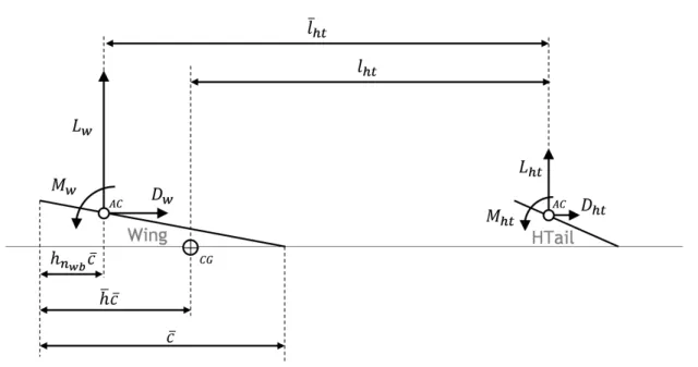
3.1 Schematic representation of the acting forces and moments on the wing and hor-izontal tail. . . 39
3.2 Propulsion model implemented for the electric motor. . . 42
3.3 Propulsion model implemented for the combustion engine. . . 45
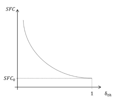
3.4 Engine SFC as a function of the power setting. . . 46
3.5 Typical propeller power coefficient (Cp) curves as a function of the advance ratio (J ). . . . 49
3.6 Typical propeller efficiency (ηp) curves as a function of the advance ratio (J ). . . 50
3.7 Diagram of forces . . . 56
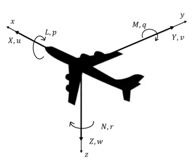
3.8 Notation of aircraft axes. . . 57
3.9 Sideslip angle and yawing moment. . . 58
3.10 Dihedral angle and rolling moment. . . 59
3.11 Static stability methodology. . . 60
3.12 Airplane orientation axes. . . 61
3.13 Velocity triangle. . . 62
3.14 Angular definitions representation. . . 63
3.15 Take-off run velocity steps. . . 64
3.16 Physical models interactions for the take-off stage. . . 64
3.17 Block diagram of the take-off subroutine. . . 66
3.18 Vertical diagram of forces of a generic flight stage. . . 67
3.19 Vertical diagram of forces of the climb stage . . . 67
3.21 Schematic representation of the climb stage height steps in the straight and turn
conditions (top view). . . 68
3.22 Physical models interactions for the climb stage. . . 69
3.23 Block diagram of the climb subroutine. . . 71
3.24 Block diagram of the descent subroutine. . . 71
3.25 Vertical diagram of forces of the cruise stage . . . 72
3.26 Schematic representation of the cruise stage time steps in the leveled flight and sustained turn conditions (top view). . . 73
3.27 Physical models interactions for the cruise stage. . . 73
3.28 Block diagram of the cruise subroutine. . . 75
4.1 Scheme featuring the system level iterative procedure for the PARROT code in the surveillance mission mode. . . 80
4.2 Scheme featuring the system level iterative procedure for the PARROT code in the maximize payload mode. . . 82
4.3 Aircraft Optimization menu. . . . 84
4.4 Main interface window. . . 84
4.5 Output data interface window. . . 85
4.6 Flight of University of Beira Interior’s model (the winner of ACC 2011) in Stuttgart, Germany. . . 86
4.7 Aircraft airfoils drag polar. . . 88
4.8 Air Cargo Challenge 2015 mission profile. . . 88
4.9 Top view schematic representation of the flight path during the 120s legs. . . 89
4.10 Performance metrics as a function of wingspan and wing mean chord. . . 92
4.11 Number of legs flown in 120s. . . 93
4.12 ACC score objective function as a function of wingspan and wing mean chord. . . 93
4.13 Air Cargo Challenge analysis - PARROT Performance. . . 94
4.14 Surveillance mission profile. . . 94
4.15 Energy weight [N] as a function of wingspan and wing mean chord. . . 98
4.16 Limits’ specifications. . . 99
4.17 Energy weight [N] as a function of wingspan and wing mean chord, including the wing aspect ratio and the wing stall velocity boundaries and the respective design point. . . 99
4.18 Structure weight and design take-off weight. . . 100
4.19 Wing incidence and dihedral angles. . . 100
4.20 Empennages surfaces’ areas. . . 101
5.1 Iteration history up to convergence (Rosenbrock case study). . . 110
5.2 Iteration history up to convergence (analytical case study). . . 112
5.3 Schematic representation of the MTOP framework. . . 113
5.4 Graphical representation of a telescopic VSW with a VCF wingspan section which uses a continuous flap for different telescopic wing extensions. . . 114
5.5 Main interface window. . . 117
5.6 Output data interface window. . . 118
5.7 Case study mission I profile. . . 121
5.8 Energy Consumption [kJ] in mission I. . . 122
5.10 Convergence of global/shared design variables - mission I. . . 124
5.11 Case study mission II profile. . . 125
5.12 Energy Consumption [kJ] in mission II. . . 126
5.13 Mission II design variables as a function of the optimization cases. . . 128
5.14 Convergence of global/shared design variables - mission II. . . 129
5.15 Case study mission III profile. . . 130
5.16 Energy Consumption [kJ] in mission III. . . 131
5.17 Mission III design variables as a function of the optimization cases. . . 132
5.18 Convergence of global/shared design variables - mission III. . . 133
5.19 Total energy and take-off weight mission (I.A) compatibility factor study. . . 135
5.20 Optimization variables mission (I.A) compatibility factor study. . . 136
5.21 Total energy and take-off weight mission (I.B) compatibility factor study. . . 137
5.22 Optimization variables mission (I.B) compatibility factor study. . . 137
B.1 Variable camber flap airfoil geometry. . . 155
B.2 Airfoil Geometry Definition. . . 155
B.3 Flapped and Unflapped Airfoil Geometry Definition. . . 156
B.4 Cantilever beam under a linearly distributed bending moment and linearly dis-tributed load. . . 157
C.1 Linear interpolation. . . 159
List of Tables
2.1 Benchmarking studies available in the literature at present time. . . 23
3.1 Power sources nomenclature explanation. . . 40
4.1 Mission profile performance inputs. . . 78
4.2 Known and unknown weight fractions in the two PARROT working modes. . . 79
4.3 Air Cargo Challenge 2015 design specifications. . . 87
4.4 Air Cargo Challenge 2015 mission profile. . . 90
4.5 Most relevant design specifications for the surveillance mission. . . 95
4.6 Surveillance mission profile requirements. . . 96
5.1 Solutions of the Rosenbrock Problem. . . 109
5.2 Solutions of the Analytical Test Case. . . 112
5.3 Distributed optimization problem formulation (LV - local variable; GV - global variable). . . 115
5.4 Weight fractions depending on the optimization mode selected. . . 116
5.5 Optimization cases for the three mission profiles considered, (P => Parameter; GV => Global Variable; LV => Local Variable). . . 120
5.6 Optimization variables bounds. . . 120
5.7 Aircraft weight distribution - mission I. . . 122
5.8 Aircraft weight distribution - mission II. . . 127
5.9 Aircraft weight distribution - mission III. . . 131
5.10 Effect of energy weighting results. . . 134
A.1 CHANGE consortium responsibilities. . . 153
F.1 Motor & Engine Specifications. . . 245
G.1 Optimized variables - MTOP case study mission I. . . 248
G.2 Optimized variables - MTOP case study mission II. . . 249
G.3 Optimized variables - MTOP case study mission III. . . 250
H.1 Running Time for each optimization case [s]. . . 251
I.1 MTOP Output Variables (I). . . 254
Acknowledgements
The current work has been partially funded by the European Community’s Seventh Frame-work Programme (FP7) under the CHANGE project (Combined morphing assessment software using flight envelope data and mission based morphing prototype wing development).
The results of my thesis are the corollary of several years of work at the Department of Aerospace Sciences of University of Beira Interior, lead by Professor Pedro Gamboa and Professor Miguel Silvestre. The completion of this thesis was only possible with the support and guidance of many people to whom I wish to leave a written testimony of my gratitude.
First and foremost I would like to thank my advisor, Professor Pedro Vieira Gamboa on behalf of his priceless commitment, assertive guidance, permanent availability and insightful advice throughout the whole of my thesis. There are no words to express how privileged I feel about working and learning with him.
I would also like to have a word of gratitude to my co-advisor, Professor Miguel Ângelo Silvestre and to Professor Kouamana Bousson for their worthy help and advice.
A special thank goes to my colleague, student and friend Filipe Fraqueiro on behalf of our fruitful collaboration on the elaboration of a graphical user interface for the two computational codes developed in the current thesis.
Many thanks to my colleague and friend Pedro Santos for his crucial support in a wide range of matters as well as for our early morning runs; and to my friend Diogo Vicente for the many useful technical discussions we had.
I thank my sister Ana Albuquerque, my wife Inês Albuquerque, my mother-in-law Mª Manuela Lopes, my mother Mª Amália Pontes Fernandes and my friends Ângela Pisco, Bruno Tojo, Hugo Lopes and Stefano Carli for their support in the revision of the current text.
I would also like to express my gratitude to my current employer, Embraer Portugal, specially to my supervisor, Engineer Sérgio Carvalho, for his flexibility, understanding and en-couragement in the final stage of my PhD.
For UBI academic community and the population of Covilhã in general for the 31 months I lived there, which I will always miss and remember with joy.
Last but not least, I would like to thank my mother for her strong personal investment and involvement in my education. I cannot thank her enough.
A final word of gratitude to all the Portuguese taxpayers for their co-funding of my aca-demic path. I will do my best to live up to my compatriots’ expectations, thus honoring and hopefully returning their investment.
Glossary
A
AAO All-At-Once
AC Aerodynamic Center
ACC Air Cargo Challenge
AoA Angle-of-Attack
ANAC Autoridade Nacional de Aviação Civil - Portugal
ASO Asymmetric Subspace Optimization
ATC Analytical Targeting Cascading
BLISS Bi-Level Integrated System Synthesis
BLISS-2000 Bi-Level Integrated System Synthesis-2000
CB Climb
CG Center of Gravity
CHANGE Combined morpHing Assessment software usiNG flight Envelope
data and mission based morphing prototype wing development
CO Collaborative Optimization
CSSO Concurrent Subspace Optimization
CZ Cruise
DT Descent
DTOW Design Take-Off Weight
EASA European Aviation Safety Agency
ECO Enhanced Collaborative Optimization
EPD Exact Penalty Decomposition
ESC Electronic Speed Control
FAA Federal Aviation Administration
FP7 European Union’s Seventh Framework Programme
FW Fixed Wing
GV Global/shared Variable
GUI Graphical User Interface
IDF Individual Design Feasible
IPD Inexact Penalty Decomposition
ISA International Standard Atmosphere
LLT Lifting-line theory
LO Lift-Off
LT Loiter
LV Local Variable
MAV Micro air vehicle
MDF Multidisciplinary Feasible
MDO Multidisciplinary Design Optimization
MDOIS MDO of Independent Subspaces
MLG Main Landing Gear
MOSFET Metal–Oxide–Semiconductor Field-Effect Transistor
MTOP MulTilevel design OPtimization
NLG Nose Landing Gear
NP Neutral Point
PARROT Parametric AiRcRaft design OpTimization
PZT Piezoelectric
QSD QuasiSeparable Decomposition
RMS Root mean square
RoC Rate-of-Climb
RoD Rate-of-Descent
s.t. subject to
SAND Simultaneous Analysis aNd Design
SFC Specific Fuel Consumption
SMA Shape-memory alloy
UBI Universidade da Beira Interior
USAF United States Air Force
VCF Variable Camber Flap
VLM Vortex Lattice Method
VSW Variable-Span Wing
VTail Vertical tail
Nomenclature
L S a linear acceleration ¯ A, ¯B, ¯D, ¯E, ¯F , ¯G, ¯K generic coefficients b wingspan c wing chord ¯c wing mean aerodynamic chord
cf flap chord
C capacitance
Cd airfoil drag coefficient
CD lifting surface drag coefficient
Cf friction coefficient
Cl airfoil lift coefficient
CL lifting surface lift coefficient
CL0 lifting surface lift coefficient at null angle-of-attack
CLα lifting surface lift curve slope
Cm airfoil pitching moment coefficient
CM lifting surface pitching moment coefficient
Cm0 airfoil pitching moment coefficient at zero lift
CM0 lifting surface pitching moment coefficient at zero lift
Clβ rolling moment coefficient derivative with respect to the side-slip angle
Cnβ yawing moment coefficient derivative with respect to the side-slip angle
Cp power coefficient
Cp0 power coefficient when the advance ratio is null
d propeller diameter
df us fuselage diameter
D aerodynamic drag
Df riction friction drag
e Span efficiency factor
˜
e0 Oswald efficiency factor
espec specific energy
E energy
f generic function
F force
F fuselage form factor
Fc centripetal force
Finertial inertial force
g acceleration of gravity
h altitude
¯
h aircraft CG position as a fraction of the wing mean aerodynamic chord
hlimit CG forward-most position
hn aircraft NP position as a fraction of the wing mean aerodynamic chord
hnwb wing plus body NP position as a fraction of the wing mean aerodynamic chord
I electric current
Ix, Iy, Iz moments of inertia about the (x,y,z) axes
J propeller advance ratio
Ji subspace level objective function
Jsys system level objective function
iht horizontal tail incidence angle
iw wing incidence angle
kC compatibility factor
kst stall velocity coefficient (quotient between minimum operating velocity
and the stall velocity)
kv motor’s speed constant
Kn static margin
lf us fuselage length
lht distance between the wing AC and the horizontal tail AC
¯
lht distance between the aircraft CG and the horizontal tail AC
L aerodynamic lift
Lm MLG length
Ln NLG length
m mass
M aerodynamic pitching moment
M Mach number
n load factor
ncseries number of battery cells in series
nlegs number of mission legs flown
N rotational velocity
Nl landing gear ultimate load factor
p propeller pitch
p, q, r scalar components of the rotational velocity ¯
p wingspan extension factor
P power
q dynamic pressure
Q fuselage interference factor
Rele electrical resistance
R radius
Re Reynolds number
S lifting surface area
u, v, w scalar components of the velocity vector
vht horizontal tail volume coefficient
¯
vht horizontal tail volume coefficient (alternative definition)
vvt vertical tail volume coefficient
Vst stall velocity
V velocity
Vf uel fuel volume
Vw wind velocity
s slack variables
S lifting surface planform area
t/c airfoil relative thickness
T thrust
U voltage
w vertical velocity, rate-of-climb or rate-of-descent
W weight
Wl landing gear design gross weight
x, y generic variables
xL local variables’ vector
xS shared variables’ vector
x∗ subspaces best attempt to match the system level targets
X, Y, Z components of the resultant aerodynamic forces acting on the airplane
z system level targets
G S α angle-of-attack αi induced angle-of-attack β side-slip angle γcb climb angle γdt descent angle
Γ wing dihedral angle
δ generic variable increment
δth engine/motor power setting
δe elevator deflection angle
δf flap deflection angle
∆t time interval
∆x distance interval
ε wing down-wash angle
ηprop propeller efficiency
ηpropmax maximum propeller efficiency
θ aircraft pitch angle
λ taper ratio
λ∗C dynamic compatibility parameter
λF feasibility parameter
λweight weighting coefficient
Λ wing aspect ratio
¯
Λ wing sweep angle
µ dynamic friction coefficient
ν kinematic viscosity of air
ξ non-dimensional damping coefficient
ρ density
τ propulsive force angle with respect to the fuselage axis
ϕ aircraft bank angle
ψ aircraft yaw angle
S S
0 reference flight condition
ac aerodynamic center
aero aerodynamic
av available
bat battery
bat0 battery with motor in idle
C center cb climb comb combustion comp compatibility cz cruise dt descent E Earth ef f effective ele electrical ene energy eng engine
i initial iter iteration f flap, final f ric friction f us fuselage ht horizontal tail i, j, k, l, n generic index limit limit lo lift-off L lower m generic index max maximum min minimum misc miscellaneous
mlg main landing gear
mot motor
n generic index
nlg nose landing gear
norm normalized
p, q, r scalar components of the rotational velocity
p propulsive
pay payload
prop propeller
ref reference aircraft
req required st stall str structures shaf t shaft step step sys systems to take-off
thr threshold
vt vertical tail
T trailing edge
T E trailing edge
u, v, w scalar components of the velocity vector
U upper
w wing
Chapter 1
Introduction
1.1
Background and Motivation
Aircraft design involves a comprehensive analysis of a wide range of mutually interacting phenomena, requiring a sound knowledge of disciplines like materials, aerodynamics, struc-tures, control, stability and performance, thus being an inherently multidisciplinary task. In-deed, aircraft design is commonly regarded as a separate design discipline [1], which is different from the former in the way that the designers need to be well versed in all of them while aim-ing to create the aircraft’s geometrical description. Nonetheless, aircraft design is probably amongst the most subjective disciplines of aeronautics which despite having its roots anchored on the laws of physics, neither it is a linear process, nor there are standardized procedures for it.
Aircraft design is an intrinsically iterative process, since there are much more unknowns than equations. Only after years of experience do designers acquire the proficiency level that not only enables them to get closer to the global optimum but also significantly reduce the optimization time, making the overall design process concomitantly more effective and effi-cient. Hence, Multidisciplinary Design Optimization (MDO) is undoubtedly of utmost relevance and a topic of intense research. In recent decades, the development of MDO architectures has shown that the disciplinary optimization breakthroughs witnessed over the last century will not be the only ones to revolutionize the design process. As an increasing number of experts and researchers devote their time to MDO, it becomes clearer that the discipline of design has got a tremendous progress margin. The possibilities these new methodologies unfold show that they will definitely pave the way of engineering design in a range of subjects that goes far beyond the aerospace industry. The significant improvements on MDO assessed and formalized by Martins et al (2013) [2], combined with the computer’s exponential increase of data handling capability show that their scope of applicability is widening. As a corollary, there has been an increas-ing interest from the industry, with a growincreas-ing number of companies adoptincreas-ing MDO in order to further enhance both their products’ design and design processes as discussed by Weck et al (2011) [3].
Another research topic in vogue is morphing. Despite not being a new concept in the sense it exists since the dawn of aviation - starting with the Wright Brothers use of wing warping - the definition of morphing adopted in this study is narrower in the way it will focus on more recent shape changing technologies, as it will be further discussed in section 2.3. Morphing technologies have been adopted with the goal of widening the aircrafts’ flight envelopes, contributing to an increased aerodynamic efficiency and optimized performance. These technologies include, but are not limited to, variable wingspan, wing dihedral, wing sweep, wing torsion, airfoil camber and variable propeller pitch.
The synergy created by the combined use of increasingly efficient solutions with the search for more versatile and capable vehicles, does clearly foster combined research works
on Multidisciplinary Design Optimization and Morphing Technologies.
While the use of unmanned aerial vehicles (UAVs) to test these ideas significantly reduces the cost and risks involved, the number of applications of this kind of vehicles has been contin-uously growing over the last decade, with the only obstacle preventing an effective boom being the scarce regulatory framework. Nevertheless this last impediment is expected to be overcome before the end of the decade, as both the European Aviation Safety Agency (EASA) and the Fed-eral Aviation Administration (FAA) are expected to issue certification specifications for the use of unmanned aerial systems. Some national certification authorities have already started issuing regulatory frameworks, like the Portuguese Autoridade Nacional de Aviação Civil [4].
In addition, it is apparent that the most significant shape-changing methodologies applica-tion to UAVs is much more likely than their use for manned aircraft, because of the wider range of multimission capabilities of UAVs with respect to manned aircraft. Yet, the performance assessment of morphing solutions done for UAVs as primary test benches as well as probable primary users can provide the cornerstones for the employment of such technologies in manned aircraft.
1.1.1
Greater Research Project
The current work has been partially funded by the European Union’s Seventh Framework Programme (FP7) (ACP2-GA-2012-314139-CHANGE-GA) under the Grant Agreement 314139. The CHANGE project’s main objective is ”to define a stepping stone to insert morphing technologies into air transport aircraft enabling the aircraft to fly with increased performance during the length of their mission.”, thus aiming to include three different morphing concepts in the same wing, something that had not been done before the start of the project, in August, 2012.
The CHANGE project (Combined morphing assessment software using flight envelope data and mission based morphing prototype wing development) is a Level 1 project involving 9 part-ners: Tekever (Portugal), DLR (Germany), ARA (United Kingdom), University of Beira Interior (Portugal), Cranfield University (United Kingdom), Swansea University (United Kingdom), In-vent (Germany), Middle East Technical University (Turkey) and the Technical University of Delft (Netherlands). The responsibilities of each member are summarized in Appendix A.
1.2
Aircraft Design
The aircraft designer needs to have a comprehensive knowledge on the mainstream disci-plines of aircraft design, namely, on materials, aerodynamics, structures, control, stability and performance. However, the most challenging part of designing an aircraft is to synthesize the mutual interactions among these disciplines in order to achieve enhanced design solutions from the earliest stages of the design process.
The holy grail of aircraft designers was, and in many cases still is, that their concepts can get through subsequent evaluations by different disciplinary experts without major changes being required. If the designer is talented, there is surely much more content on the drawing than what the eye can perceive. Globally, it can thus be said that the earliest stages of the aircraft design process are about a powerful and duly weighted mix of intuition and knowledge.
However, the increasing number of disciplines, the ever greater complexity of the physical mod-els that depict current technologies and the multiple couplings between disciplines makes this task to some extent herculean.
For the successfulness of this demanding undertaking, an increasing number of design companies are adopting the so-called Multidisciplinary Design Optimization (MDO) methodolo-gies (section 2.1). These solutions can not only be far more encompassing than human brains but also provide a quantitative output. Nonetheless, the profitability of using MDO methodologies is uneven throughout the design process.
It can be said that the aircraft design process is divided in three major steps: Conceptual Design, Preliminary Design and Detailed Design, respectively, as depicted in Figure 1.1. While the earlier Conceptual Design stage decision making-process is commonly still based on the designers’ themselves, MDO methodologies have proven that they can be particularly worthwhile in saving time and resources while getting closer to the global optimum at the Preliminary Design stage [2].
Figure 1.1: Aircraft design steps.
It is important to stress that this schematic representation of Figure 1.1 fails to provide a feeling of both the relative time span of each major step as well as to reveal that these stages are usually not exactly sequential. The most timeconsuming step is obviously the Detailed Design -where literally all parts will be designed, analyzed and tested - -whereas the Conceptual Design is the fastest stage - where the analysis is much more generic and largely qualitative. Moreover, these steps are not fully sequential in the way there is an actual time-line overlap between the end of Conceptual Design and the beginning of Preliminary Design as well as the end of Preliminary Design and the beginning of Detailed Design. This happens because aircraft design is not straightforward. As a matter of fact, it is an indelible iterative task, where it is common place to go upstream in the design process as a result of analysis’ findings.
1.2.1
Conceptual Design
As depicted in Figure 1.1, the conceptual design phase follows the design requirements definition, thus being the first of three major steps that are usually present in the design of any aircraft. First and foremost, the designer shall determine if the design requirements lead to a feasible vehicle. If that is not the case, one should go back to the design objectives definition and loosen up one or more requirements. Secondly, an usual concern is about the aircraft’s affordability. Likewise, if this is not met, the design requirements might be relaxed, depending on the vehicle’s purpose.
At this stage the designer’s goal is to answer the fundamental questions of design arrange-ment, like aircraft configuration, size, weight and cost. This is a stage where the experience of the designer is absolutely paramount to getting closer to the optimum and to do it within the least possible amount of time, as there is a great design freedom. It usually starts with a so-called brainstorming where literally all ideas are considered and is followed by some rough analysis and sizing methodologies which will tend to eliminate inefficient or poor-performing solutions with the objective of narrowing down the number of possible configurations. At the end of this stage, the main design concepts shall be frozen.
1.2.2
Preliminary Design
The Preliminary Design stage aims at defining the vehicle’s dimensions and geometry. At the beginning of this stage, the aircraft configuration shall be frozen. At this point, the disciplinary experts will design and analyze their respective part of the aircraft, (e.g. landing gear, structure, flight controls). Some actual testing in areas like aerodynamics, propulsion, performance and controls shall also begin.
However, the most important task at this stage is what is usually called ”lofting”. Its goal is to define an appropriate geometrical definition of the outside skin of the aircraft while ensuring a proper fitting between the various components. Despite current industrial practice breaking up the design task between different design groups, with the major aircraft manufacturers commonly subcontracting many smaller companies to develop specific parts of the aircraft, the lofting is usually performed by the aircraft manufacturers themselves. This is concomitantly justified by the relevance of the task to the success of the design and due to confidentiality requirements.
At the end of this stage, the designers should be absolutely confident that the aircraft can perform as required and provide reasonably accurate costing estimates and delivery date. This is usually known as ”you-bet-your-company” as meaningful flaws will impact the designer’s com-pany image and will most likely incur in financial losses, and ultimately can lead to bankruptcy.
1.2.3
Detailed Design
The detailed design stage name is largely self-explanatory about its goal of developing the actual design of all the smaller parts and components with the greatest detail. If the wing layout and perhaps the wing box have been designed at the preliminary design stage, now the goal is to design its ribs, spars, skin, bolts and rivets. At this point, the structure sizing is made using high fidelity computational methods to make sure the vehicle will perform according to its
operational requirements complying with the applicable certification specifications established by the civil aviation authorities or military specifications, depending on the vehicle’s target market segment. The ultimate structural studies, also include ground and flight experiments to physically accept the compliance with the regulations.
At this design stage, several minor modifications to the original design shall be at stake. Some of them will be accepted in order to ease production or lower manufacturing times and costs, whereas some others will not because they would have an unacceptable impact on per-formance or weight. This is probably one of the most thrilling undertakings at this stage - the compromise between various disciplinary experts. Globally, it must be assured that none of these changes impact the original design requirements.
The manufacturing of the whole aircraft will follow this last design stage. In most cases however, some components and parts shall still undergo detailed design concurrently with early manufacturing of other components and parts.
1.2.4
Design Optimization Programs
The most challenging part of a high performance design is to synthesize the mutual inter-actions among disciplines in order to achieve enhanced design solutions at the earliest stages of the design process. However, the large number of disciplines, the complexity of the aircraft physics and the multiple couplings between disciplines complicates this task.
Nevertheless, the development of comprehensive multidisciplinary design codes is grad-ually contributing to a paradigm change, in the way it is expected to revolutionize the design process. While the earlier conceptual design phase decision making-process is commonly still based on the designers themselves, multidisciplinary design optimization methodologies have proven that they can be particularly worthwhile in saving time and resources while getting closer to the global optimum at a preliminary design stage, as shown by Martins et al (2013) [2].
Amongst the different multidisciplinary design programs which include a graphical user interface, it is worthwhile to mention some cornerstone developments in the context of aircraft disciplinary analysis and design optimization.
One of the earliest such works was the Advanced Aircraft Analysis (AAA) [5], a tool which enables aircraft design and optimization as it allows a wide spectrum of analysis, although this is a complex software and a license is required to use it. AAA is divided into ten independent modules such as weight, aerodynamics, performance, stability and controls, among others. Due to its multidisciplinarity, this software allows a comprehensive aircraft design analysis and op-timization even though the latter is generally user guided through an informal process.
CEASIOM (Computerized Environment for Aircraft Synthesis and Integrated Optimization Methods) [6] is a freeware software featuring a geometry module which makes it possible to have a general view about the aircraft geometry under analysis. It also includes modules related to stability, controls and aerodynamics.
It is also worthwhile to refer XFRL5 [7], which was developed by André Deperrois. It uses XFOIL for the 2D airfoil analysis and VLM or LLM for 3D wing analysis. XFOIL [8] was developed at the Massachusetts Institute of Technology, being a widely known code to calculate airfoils’ aerodynamic coefficients. Despite being an accessible and widely used tool, XFLR5 does not enable automatic optimization of airfoils, lifting surfaces and/or fuselages. Conversely, the
analyses data can be used by the designer for optimization purposes, but the overall optimization workflow will be far more toilsome.
A more recent example of design optimization programs is SUAVE [9] – developed at Stan-ford University in collaboration with Embraer – which is a comprehensive tool with four calcula-tion methods: Tradicalcula-tional Aircraft Design, Advanced Configuracalcula-tion/Unconvencalcula-tional Technology Design, Optimization, Aircraft/Discipline Analysis. SUAVE is an open source and has been written with the Python language. It can be incorporated using extensible interfaces and prototyped with a top-level script that allows the creation of arbitrary mission profiles, unconventional propulsion networks, and right-fidelity at right-time discipline analyses.
Other tools have been developed, which enable the assessment of morphing technologies. Suleman et al (2014) [10] have detailed a MDO framework for conceptual design and analysis of new aircraft configurations, including the capability to analyze and quantify the effect of mor-phing wing solutions on aircraft performance. Two main modifications to the MDF architecture were implemented. The first change consisted on replacing the real models (aircraft disciplines) by surrogate models; the second modification is rather more particular and was specially intro-duced in the MDO Framework to better suit the capabilities of the aircraft to morph during flight by splitting up the general aircraft configuration optimization and control optimization of each performance goal in two levels of MDO problems. The first/lower level is responsible for de-termining the best morphing strategy for the selected performance metric. So for each chosen metric a MDO problem is defined. The selected performance parameter is set as the objective and the variables able to change during flight can be employed as design variables (for example: aerodynamic controls, morphing devices and engine controls). In the upper/second level, the geometric configuration variables are optimized. The performance parameters optimized in the lower level can be included in a weighted multi-objective function and/or in the MDO problem set of constraints. It has been shown how the devised MDO framework can contribute to an enhanced design of a conventional wingtip and proved that a morphing wingtip would probably present no advantage due to its low aerodynamic gains compared to its weight penalty.
Lyu and Martins (2015) [11] have shown that adaptive morphing trailing edge wings have the potential to reduce the fuel burn of transport aircraft. The effectiveness of the trailing edge morphing was demonstrated by comparing with the optimized results of a hypothetical fully morphing wing. From an aerodynamic perspective, an adaptive morphing trailing edge can easily offer additional drag reduction without a complete redesign of the wing (1% drag reduction at on-design conditions, and 5% drag reduction near off-design conditions). However, to provide a comprehensive evaluation benefit, a multidisciplinary study is required to examine the trade-offs between aerodynamics, structures, and controls.
Adaptive morphing trailing edge technology offers the potential to decrease the fuel burn of transonic transport aircraft by allowing wings to dynamically adjust to changing flight con-ditions. Conversely, current aircraft use flap and ailerons to adjust the wing during flight, thus introducing unnecessary drag. Burdette et al (2015) [12] have compared a standard non-morphing wing against a wing retrofitted with a non-morphing trailing edge, and a clean sheet wing designed with the morphing trailing edge. The morphing trailing edge was found to achieve fuel burn reductions via two mechanisms. The first was its ability to improve maneuver load alleviation, allowing for lighter wing structures. The second was a reduction of the coupling between the cruise and maneuver cases, which allows the cruise configuration to improve with-out causing adverse effects on maneuver performance. The wing retrofitted with the morphing
trailing edge improved the fuel burn as effectively as the full wing redesign without morphing. Additional fuel burn reductions were observed for the clean sheet design. The morphing trailing edge decreased the fuel burn by performing load alleviation at the maneuver condition, weak-ening the trade-off between cruise performance and maneuver structural constraints, resulting in lighter wing-boxes and more aerodynamically efficient cruise configurations.
Vale et al (2016) [13] have also used multidisciplinary design optimization in a comparative study between the lift over drag ratio (L/D) performance of a fixed wing glider and a camber morphing wing glider, featuring aerodynamics, structures and static stability analyses. The proposed camber morphing concept featured a coupled effect of changing the wing twist. For that reason, and for the sake of computing efficiency, the CMWG MDO procedure is a sequential optimization, with the goal of converging the wing twist on the surrogate and FEM, while the FWG MDO procedure is a single level optimization. The results indicate that the CMWG can effectively reduce the magnitude of the load factor experienced by the aircraft.
1.2.4.1 Work Scope
The current work aims at providing a comprehensive multidisciplinary framework for mission-based optimization of morphing aircraft. In particular, and contrarily to the afore-mentioned methodologies, one aim to tailor the optimization methodology for the assessment of morphing technologies. In addition to the development of an arbitrary mission-profile based on generic flight conditions and adaptive technologies, the iterative propulsion model matches the blade versus motor/engine performance for any combination of velocity, altitude, throttle setting and required power.
1.3
Objectives
This PhD thesis’ main goal is the development of mission-based state-of-the-art aircraft design optimization methodologies that can contribute to an efficient (not costly) and effective (accurate) preliminary design stage. Two computational codes have been created using the mainstream disciplines of aeronautical design: aerodynamics, propulsion, mass distribution, static and dynamic stability and performance. In addition, these tools enable the assessment of adaptive technologies. In order to make the codes easily usable by any interested aircraft designer, the development of a user friendly graphical user interface is also part of the current research project goals.
1.4
Contributions
The core contributions of this thesis are two preliminary UAVs design optimization method-ologies - a PARametRic aircraft design OpTimization (PARROT) and a MulTilevel aircraft design OPtimization (MTOP), which distinguishing feature is the fact of being mission-based optimiza-tion methodologies, which means that the aircraft is being optimized for a specific mission profile, rather than being optimized for cruise conditions. The latter enables the assessment
of morphing technologies. These two methodologies have been materialized in two different codes largely sharing the physical analysis’ models.
The former methodology enables the user to optimize the wing layout (wing mean chord and wingspan) for one of two different goals: maximum endurance/range mission or maximum payload, whereas the latter relies on a multidisciplinary and multilevel design optimization methodology combined with the use of morphing solutions making it possible to optimize the UAVs for a more detailed pre-defined mission profile.
1.5
Thesis Structure
The current thesis is divided into four main chapters: State-of-the-art Review (2), Analysis Models (3), Parametric Design Optimization (4) and Multilevel Design Optimization (5).
Chapter 2 introduces the basic definitions and provides an overview on the latest develop-ments in MDO, particularly on distributed optimization architectures, highlighting present and future challenges. An insight on morphing technologies is also included.
Chapter 3 describes the analysis models used in the development of the two codes. It in-cludes a comprehensive overview of the disciplinary models (e.g. aerodynamics, weight, propul-sion and stability), a description of the possible mispropul-sion stages (e.g. take-off, climb, cruise) flight mechanics and also specific modifications tailored for morphing technologies.
Chapter 4 presents a mission-based parametric study-based aircraft design optimization methodology and explains how the PARROT code has been developed highlighting the merits of such approach with several case studies. This chapter also includes a description of the PARROT’s graphical user interface.
Chapter 5 features a mission-based distributed aircraft design optimization methodology and thoroughly describes the MTOP code, presenting the merits of this broader approach along the discussion of several case studies, which, among other advantages, can assess the profitabil-ity and optimize the use of morphing technologies. In addition, this chapter also features an overview of MTOP’s graphical user interface.
Notwithstanding that each chapter includes short introduction and concluding sections, the conclusions from the design optimization methodologies and computational implementations are summarized in Chapter 5. Future work and recommendations are also presented in this last chapter.
Chapter 2
State-of-the-art Review
2.1
Multidisciplinary Design Optimization
As shown by Gohman et al (2012) [14] and already discussed, the design of future aerial vehicles requires the consideration of multiple and interacting disciplines as well as different design goals, like lowering manufacturing and operational costs, minimizing weight without compromising structural behavior or lowering emissions without jeopardizing performance. As shown by Martins and Lambe (2013) [2] and La Rocca et al (2009) [15], Multidisciplinary Design Optimization (MDO) is definitely of utmost relevance in the quest for these goals.
The works of Schmit et al (1960, 1981 and 1984) [16–18] and Haftka et al (1973, 1977 and 1979) [19–21] are the genesis of MDO when they widened the scope of their structural design optimization to other disciplines, the first applications being wing design, where there is an inherent coupling between aerodynamics, structures and controls.
In recent years, however, MDO algorithms have been extended to the full aircraft, Kroo et al (1994) [22] Antoine et al (2005) [23] and Henderson et el (2012) [24]. In this context, the works of Wakayama et al (2000) [25] that developed a comprehensive MDO methodology for aircraft preliminary design, of Gur et al (2010) [26] that developed a complete design opti-mization study for a wing and the work of Gohmal et al (2012) [14] that developed a conceptual multifidelity, multistrategy and multidisciplinary design optimization for a generic jet wing are noteworthy.
There have been several surveys of MDO over the last 25 years. Haftka et al (1992) [27] were among the first to review the MDO architectures. Cramer et al (1994) [28] formalized the monolithic architectures and detailed the required optimization algorithms (gradient-based methods). Balling and Sobieski (1996) [29] identified a number of possible monolithic approaches and estimated their computational cost.
In a collection of articles edited by Alexandrov and Hussaini (1997) [30], Kroo et al (1997) [31] provided a comprehensive overview on MDO, including a description of both mono-lithic and distributed architectures. Later, in that same year, Sobieski and Haftka (1997) [32] published an exhaustive survey of the MDO literature known at that time.
More recently, Martins and Lambe (2013) [2] have presented a survey of all the optimiza-tion architectures presented in the literature by the time of its publicaoptimiza-tion. In this review, the architectures have been compared using a unified nomenclature, which is adopted through-out this thesis, since this work is concomitantly the latest and most comprehensive effort to benchmarking the existing methodologies.
The forthcoming paragraphs include some introductory remarks to numerical optimiza-tion concepts (subsecoptimiza-tion 2.1.1) and are followed by a thorough yet abridged overview on the two fundamental MDO architecture categories - Monolithic (subsection 2.1.2) and Distributed (subsection 2.1.3).
2.1.1
Introduction to Numerical Optimization Concepts
Before providing a quick but comprehensive overview of the multidisciplinary design op-timization architectures developed so far, it is important to provide some relevant definitions with which the reader may not be fully acquainted:
• compatibility: is what happens to variables that are shared among different subspaces at the end of multilevel optimization schemes;
• condition number <> gradient: of a function with respect to an argument measures how much the output value of the function can change for a small change in the input argument; • consistency constraints: in system design, consistency enforces that both the target and
actual variable values are the same;
• convex design space: a design space is said to be convex if the line segment between any two points on the graph of the function lies above the graph;
• design constraints: in system design, these constraints are usually externally imposed, either by one organization, some external regulation or some other disciplinary groups working on the same project;
• feasibility: is the set of all possible points (sets of values of the choice variables) of an optimization problem that satisfy the problem’s constraints, potentially including inequal-ities, equalinequal-ities, and integer constraints. It is thus the initial set of candidate solutions to the problem, before the set of candidates is narrowed down;
• sensitivity analysis: a technique used to determine how different values of an indepen-dent variable will impact a particular depenindepen-dent variable under a given set of assumptions; • objective function: in linear programming, the optimization goal is to maximize or min-imize a given function or a linear combination of mathematical functions which measure physical quantities of interest. The objective function minimization or maximization is thus the ultimate optimization target;
• optimization:
distributed: the original problem is partitioned into a number of subproblems each with its own subset of variables and constraints, (subsection 2.1.3);
monolithic: optimization where a single optimization problem is being solved, (sub-section 2.1.2);
multilevel: is a special kind of optimization where one or more problem is embedded within another in cascade fashion and is a particular type of distributed optimization where there is a hierarchy among the different problems;
• variable:
coupled: exhibits some kind of dependence on some other variable; independent: does not have any kind of dependence;
local: is not shared among disciplinary analyses;
shared/global: is shared by different disciplinary analyses;
state: one of the set of variables that are used to describe the mathematical ”state” of a dynamical system. The state of a system describes enough about the system to determine its future behavior in the absence of any external forces affecting the system. Models that consist of coupled first-order differential equations are said to be in state-variable form; • surrogate model: is a method used when an outcome of interest cannot be easily directly
measured, and a model of the outcome has to be built to be used instead;
• well-conditioned: a problem with a low condition number is said to be well-conditioned, which means the output value of a function does not significantly change due to small changes in the input argument.
Despite the fact that different MDO architectures can be used to solve the same problem, the architecture’s choice has shown to have great influence on both the solution time and the final design. The same goes for the optimization algorithm employed, e.g. on the one hand the use of a purely gradient-based algorithm may result on the solution getting prematurely stuck in a local maximum or minimum, on the other hand the computational cost of a such choice is likely to be considerably lower than most non-gradient-based algorithms.
As per Martins and Lambe (2013) [2], the optimization architectures can be categorized in the groups shown in Figure 2.1.
Figure 2.1: MDO architectures.
2.1.2
Monolithic Optimization Architectures
If the boundaries between the different disciplinary analyses are disregarded, an MDO problem is reduced to a standard constrained nonlinear problem which means finding the op-timum combination of design variables that minimizes or maximizes the design objective func-tion subject to its constraints. The architectures presented in this subsecfunc-tion are referred to as Monolithic architectures. These solve a single optimization problem, with different strategies being adopted for the sake of multidisciplinary feasibility.
optimization problem from which all the others are derived - All-at-Once (AAO) problem - will be presented. The definition of AAO problem adopted in the current work, is in line with the ones presented by Cramer et al (1994) [28] and Martins and Lambe (2013) [2], which corresponds to “the most general formulation”. Accordingly, the AAO problem includes all the design, state, input and output variables. However, the optimization problem is never solved in this AAO architecture because the consistency constraints can be easily eliminated.
The remaining three optimization architectures - Simultaneous Analysis and Design (SAND), Individual Design Feasible (IDF) and Multidisciplinary Design Feasible (MDF) - can be found by eliminating equality constraints to this fundamental AAO formulation, as depicted in Figure 2.2. The reader should be aware that despite the formulation differences presented below, the problem being solved is always the same.
Figure 2.2: Schematic representation of the different monolithic architectures.
2.1.2.1 Simultaneous Analysis and Design (SAND)
A logic step following the AAO formulation is to eliminate the consistency constraints, which can be done by introducing a single group of coupling variables to replace the separate target and response groups, as discussed by Haftka (1985) [33].
In this formulation, there is no need to solve any discipline analysis explicitly or exactly at each iteration, which results that the optimization problem can potentially be solved rather quickly by letting the optimizer explore regions that are infeasible with respect to the design constraints. Additionally, the SAND methodology is not restricted to multidisciplinary systems and can be used in single-discipline optimization as well. Contrarily, this problem formulation still requires all state variables and discipline analyses to be known and therefore problem size and potential premature termination of the optimizer at an infeasible point are issues of concern. The discipline analysis equations are treated explicitly as constraints, which means the residual values - and possibly their derivatives - need to be available to the optimizer. However, it is important to note that even if the software can be modified to return the residuals, the cost and effort required may be excessive, according to Haftka (1985) [33].
2.1.2.2 Individual Design Feasible (IDF)
The Individual Design Feasible (IDF) architecture is reached by eliminating the consistency constraints from the AAO formulation.
IDF enables the discipline analyses to be performed in parallel, since the coupling between disciplines is resolved by the coupling variable copies and consistency constraints. As a conse-quence, the IDF problem is substantially smaller than the SAND, requiring minimum modification to the existing discipline analysis, which is one of the main assets of this formulation.
Conversely, if the number of coupling variables is too large, the resulting optimization problem might be too heavy to solve efficiently. When the disciplinary analyses are expensive, evaluating the objective and constraint functions’ gradients becomes costly. In practice gra-dients are estimated using some finite-differencing procedure. While this approach preserves discipline feasibility it is costly and unreliable Martins and Lambe (2013)[2].
For a comprehensive overview on the available options for computing derivatives in MDO problems, the reader is encouraged to see the work of Martins and Hwang (2013) [34].
2.1.2.3 Multidisciplinary Feasible (MDF)
The Multidisciplinary Feasible (MDF) problem formulation, presented by Cramer et al (1994) [28] - also known in the literature by fully integrated optimization (Alexandrov and Hus-saini (1997) [30]) and by nested analysis and design (Balling and Sobieszczanski (1996) [29]) - is as small as it can be for a monolithic architecture, since only the design variables, objective function and design constraints are under the control of the optimizer. Accordingly, this formu-lation is obtained after removing the analysis and consistency constraints from the AAO problem (thus combining the SAND and IDF architectures).
MDF returns a system design that always satisfies the consistency constraints, even if the optimization process is terminated early. However, as per Martins and Lambe (2013) [2], the design constraints satisfaction may not be guaranteed.
A consistent set of coupling variables must be computed and returned to the optimizer every time the objective and constraint functions are evaluated. MDF requires a full multidis-ciplinary analysis to be performed at each iteration. Instead of simply running each individual discipline analysis once per iteration, as in IDF, it requires running every analysis multiple times until a consistent set of coupling variables is found.
For instance, the block Jacobi coupling process is considered to be the most conceptually straightforward iterative approach for strong coupling of two or more codes, Matthies et al (2006) [35]. The Gauss-Seidel iterative approach, however, has shown to converge faster than block Jacobi coupling because it uses information about the dependent parameters as soon as they become available, Ismail Farajpour and Sez Atamturktur (2012) [36]. Newton-like methods offer gradient-based iterative coupling techniques relying on the Newton iterations completed on the Jacobians in the coupled system of equations.
Furthermore, gradient calculations are also harder for MDF than IDF. While in IDF gradi-ent information must be discipline-feasible, in MDF the gradigradi-ent information must be feasible with respect to all disciplines, because a full multidisciplinary analysis is performed at each it-eration. However there are several semi-analytic methods that contribute to a very significant