1. INTRODUCTION
The vector from the robotized aerial system acts the same as piloted airships having the same aerodynamic laws. While projecting a lift surface type fl ying wing an important aspect would be maneuverability and stability which is directly infl uences by geometrical characteristics used in the designing phase.
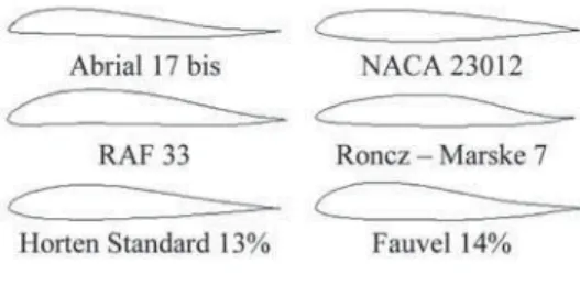
Normally airships type fl ying wing could have lift surfaces with any aerodynamic profi le, everything else resuming to the type of mission and the performance of the bearing surface. To design such an airship at a large operating scale, the wing must present optimal geometrical characteristics so it can maintain induced resistance, the moment coeffi cient and the lift coeffi cient at suitable levels. A few aerodynamic profi les used at tailless airships are represented in Figure 1.
Figure 1 Airfoils for fl ying wing
The majority of the aerial vectors for the fi xed wing have a conventional geometry with the tail, the low cost design determining to create a tailless project that has a blended wing or not, see fi gure 2. [1]
a) b) c)
Figure 2. Flying wing UAV. Model free plan, b. Scan Eagle, (a.
USA, c. Maxi 10, France)
THE AERODYNAMIC ANALYSIS
OF THE PROFILES FOR FLYING WINGS
Vasile PRISACARIU
Transylvania University, Brasov, Romania
The possibility of using an un-piloted aerial vector is determined by the aerodynamic characteristics and performances. The design for a tailless unmanned aerial vehicles starts from defi ning the aerial vector mission and implies o series of geometrical and aerodynamic aspects for stability. This article proposes to remark the aerodynamic characteristics of three profi les used at fl ying wing airship through 2D software analysis.
Mainly there are 3 types of fl ying wings determined by obtaining longitudinal stabilization: plank (fi g. 2a), swept (fi g. 2b) and parafoil (fi g. 2c).
By choosing one of the longitudinal stabilizations we use a series of aerodynamic profi les corresponding to the momentary coeffi cient (low values), as examples we choose Phoenix and Clark YH profi les for plank and swept wings and MH 91 for parafoil wings (see fi gure 3)[2, 3].
Figure 3. Airfoil for fl ying wing
2. THEORETICAL LANDMARKS Aerodynamic analysis for airfoil reveals limits of performances can be obtained: the angle of incidence for zero lift (α0), the angle of the incidence for zero drag (Cd)min, maximum smoothness (Cd/Cl) min (fi gure 4), the angle of incidence at maximum lift – (Cl)max. [4]. Incidence reference values are shown in Figure 5.
Figure 4. Dependence of lift coeffi cient (Cl) and drag coeffi cient (Cd) with angle
of incidence (α)
Figure 5. The classic polar
For performances calculus is necessary an explicit dependence of Cd= Cd(Cl). Show in fi gure 4 a linear variation of Cl small incidence angles above 70 but the variation is nonlinear because of the separation of fl uid layers. We have:
(
ed
d C M R
C = a, , ,Cl=Cl(a,M,Re) (1)
removed α, result:
(
C M R)
C
Cl = l d, , (2)
Variation of the coeffi cients is show in fi gure 5 with M and Re known and constant, where: M – nr. Mach, Re – nr. Reynolds
(3) 2 1 2 b c v L cl ∞ ∞ = r 2 1 2 b c v D cd ∞ ∞ = r (4) 2
1 2 2
0 0 b c v M cm ∞ ∞ = r (5)
3. AERODYNAMIC ANALYSIS
3.1. Profi li v.2.21software
For the 2D analysis we choose the profi les from fi gure 6 which are mainly used in building tailless aerial vectors, the analysis being performed by Profi li 2.2.1 software [5] using the data from table 1.
Figure 6. Airfoils
The analysis methodology for comparative graphics is described in the diagram in fi gure 7.
Figure 7. Analysis methodology [5]
Table 1. The conditions of the analysis
Features Value
CMA(mm) 400
Flight height (m) 100
Angle of incidence (0) - 5 ÷ 15
Speed (m/s) 10 20 30
Reynolds number Re 272000 543000 815000
For speed of 10 m/s (Re = 272000) the polars of three airfoils are shown in fi gure 8 (a, b, c).
Figure 8 a. Chart Cl-Cd
Figure 8b. Charts Cl - angle of the incidence, Cd – angle of incidence
The characteristics the three profi les are shown in table 2. [5, 6].
Table 2. Airfoil features Features Phoenix Clark
YH MH 91 Thickness: 8,2% 11,9% 15%
Camber: 2,8% 6% 1,7% Max CL: 1,17 1,11 1,11
Max CL
angle: 11 15 15
Max L/D: 92,61 32,83 20,09 Max L/D
angle: 7 4,5 3
Zero lift
angle -0,69 -2 0
We can see in the graphs (fi gure 9) pressure coeffi cient variation (Cl) reported at airfoil chord depending angle of incidence (α) at Re = 272000 for minimum speed of 36 km/h. We observe pressure coeffi cient (Cl) that is infl uenced by camber.
Analysis of the airfoil, made at Re = 272,000, in the case the curvature changes (fl aps out at 50 and 100) to 20% of chord, show increasing lift coeffi cient (Cl) and change the value of the moment coeffi cient (Cm), as graphs in fi gure 10 (a, b ), fi gure 11 (a, b ), fi gure 12 (a, b ).
Flaps 00 Flaps 50 Flaps 100
3.2. Easy CFD v.4.1
It is a calculation instrument used for the fl uid dynamic based on the numerical solutions of the fl uids and heat transmission in Cartesian coordinates systems. We present the analysis with EASY CFD_G v.4.1 which is realized according to the methodology from fi gure 13 and the data from table 4 so we can fi nd out the pressure coeffi cient that is around the three profi les which are subjected to laminar stream.
Figure 10 a. Phoenix airfoil, the charts Cl – angle of incidence, Cd – angle of incidence
Figure 10 b. Phoenix airfoil, the charts Cl/Cd – angle of incidence, Cm – angle of
incidence
Figure 11 a. Clark YH airfoil , the charts Cl – angle of incidence, Cd – angle of incidence
Figure 11 b. Clark YH airfoil, the charts Cl/Cd-angle of incidence,
Cm – angle of incidence
Figure 12 a. MH 91 airfoil , the charts Cl – angle of incidence, Cd – angle of incidence
Figure 12 b. MH 91 airfoil, the charts Cl/ Cd – angle of t incidence, Cm – angle of
Table 3. Analysis data Meshing unstructured Mesh spacing
method uniform Mesh elements
(max) 3000
Regime steady-state
Thermal effects isothermal
Iteration 100 Airfoil incidence 00
The speed and pressure prints are remarked in fi gure 14. The validation of the analysis presented in Easy CFD_G v.4.1 could be start ups for deeper studies with refi nements for the initial entry conditions for fl ow and advection models.
for small Reynolds numbers which can lead to instability. The best compromise for a UAV fl ying wings is to adapt curved moderate line of the profi le with a maxim curve moved to the leading edge [8].
Recent research with the help of the software led to the design of new profi les with multiple applications without too much experimental effort. The applications in unmanned aerial vehicles request abnormal qualities that are not met at piloted airships: maneuverability at small speeds and high overload.
ACKNOWLEDGMENT
The authors wish to thank the Transilvania University of Brasov and “Henri Coand ” Air Force Academy of Brasov for supporting the research necessary for writing this article.
REFERENCES
[1] UAS Yearbook, Unmanned aircraft systems – The Global Perspective 2011/2012, Blyenburg & Co, june 2011, Paris, ISSN 1967-1709, p. 216
[2] Airfoils database, www. airfoiltools.com, Available at 10.12.2012
[3] Airfoils, ww.aerodesign. de/english /profi le/profi le_s.htm, Available at 10.12.2012
[4] Deliu Ghe., Mecanica aeronavelor, Editura Albastr , 2001, Cluj-Napoca, ISBN 973-650-029-2, p. 375
Limits and options of the software
Profi li 2.2.1 offers an aerodynamic analysis with a series of instruments and criteria which lead to a high trusted result. The most important analysis instruments are: profi le manager (with a data base that contains 2000 profi les), Reynolds calculator (rope functions, speed and altitude), polar analysis profiles, speed and relevant analysis coeffi cients for profi le fl ow (pressure, friction).
EASY CFD_G v.4.1 is simple software, mainly oriented for educational purpose becoming a valorous instrument for a fi rst analysis. It presents a few options and characteristics which recommend him: laminar or turbulent fl ow, isothermal or non-isothermal fl ow, steady-state or transient fl ow, structured and unstructured mesh generation, two turbulence models, conduction in solid and conjugate heat transfer, multi component fl uid fl ow, transport of passive scalars (smoke), geometry import from DXF or point data fi les [7].
4. CONCLUSIONS
[5] Duranti S. Profi li 2.21 software, 2012, Feltre-Italia, www.profi li2.com, Available at 12.12.2012
[6] Airfoil tools, www. worldofkrauss.com, Available at 14.12.2012
[7] Gameiro Lopes A.M., Easy
CFD_G user manual, 2012, p. 98
[8] Airfoils for tailless airplanes,
http://www.mh-aerotools.de /airfoils/

![Figure 7. Analysis methodology [5]](https://thumb-eu.123doks.com/thumbv2/123dok_br/18249192.342094/3.744.91.644.459.950/figure-analysis-methodology.webp)


