Stationary air conditioning, refrigeration, heat pump equipment and stationary fire protection systems on the European market and operating with fluorinated greenhouse gases (f-gas), such as R407C, R134a, R410A, must comply with the F-gas regulation: (EC) No. The f-gas regulation also requires operators to use all measures that are technically feasible and do not entail disproportionate costs to prevent leakage of these gases, to test for leakage regularly and to recover f-gas during service and maintenance of equipment. and before disposing of equipment. Before proceeding with the installation of Liebert XD cooling modules, read all instructions, verify that all parts are included, and check the nameplate to ensure that the voltage of the Liebert XD cooling module corresponds to the available power supply.
Before beginning any action that may cause a disturbance to the cooling function of the Liebert XD system, the facility manager MUST be notified. Additionally, once action is taken and work is completed, the facility manager MUST be informed. A field-supplied disconnect switch for the Liebert XDO power supply must be installed at eye level in the room with the Liebert XDO to provide emergency shutdown in accordance with local electrical codes.
L IEBERT XDO C OMPONENT L OCATIONS AND M ODEL N UMBER N OMENCLATURE
I NTRODUCTION
Pre-Installation Checks
Packing List
Optional Items
Installation Considerations
Room Preparation
G ENERAL P RODUCT I NFORMATION
Product/System Description
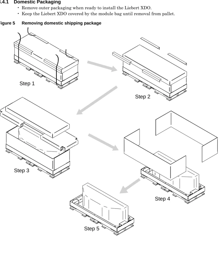
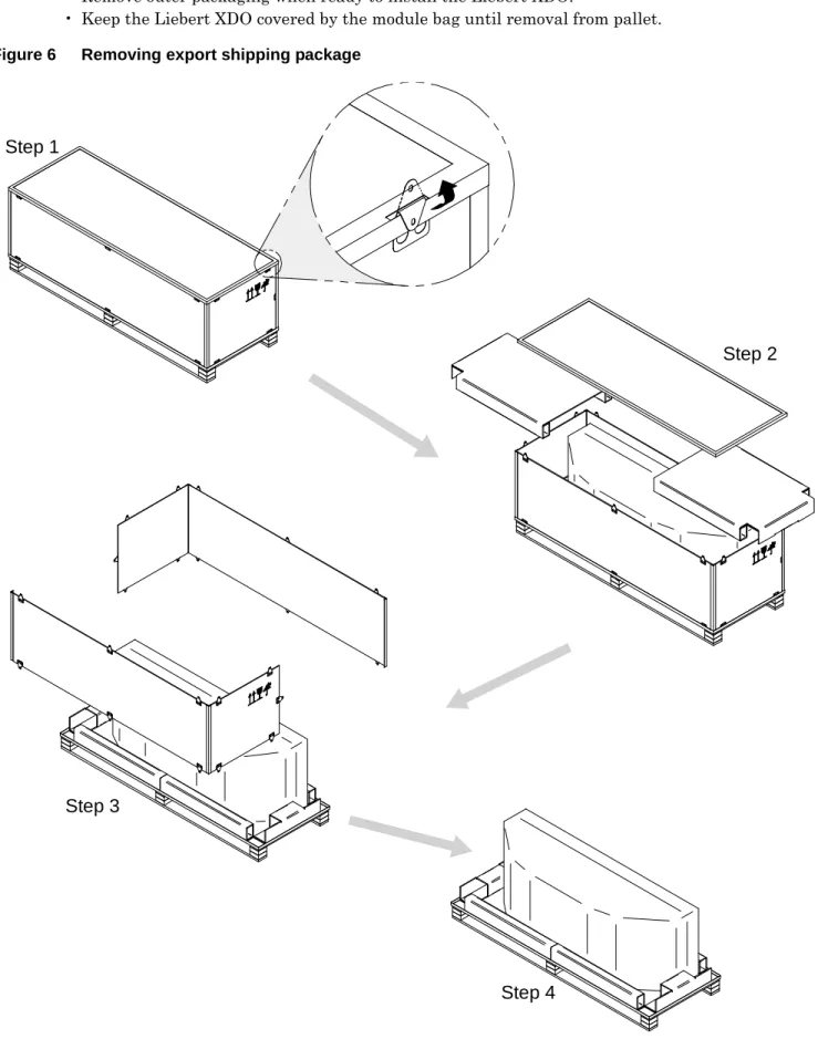
Checking and Unpacking
Recyclable Packaging
Keep the hoops level with the fork and at a suitable height to fit under the pallet.
Module Handling
Unpacking the Module
Domestic Packaging
Export Packaging
Removing the Liebert XDO from the Pallet
M ECHANICAL C ONSIDERATIONS
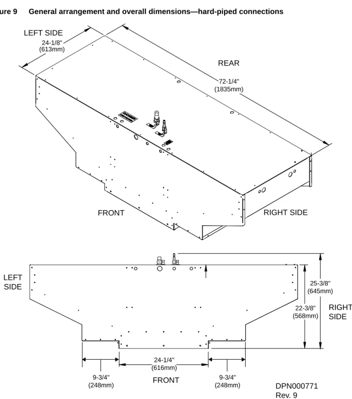
Liebert XDO Dimensions
Determining Placement in Overhead Space
Weight Distribution
Leveling
Ceiling Preparation
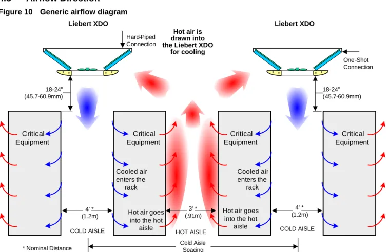
Airflow Direction
I NSTALLING THE M ODULE
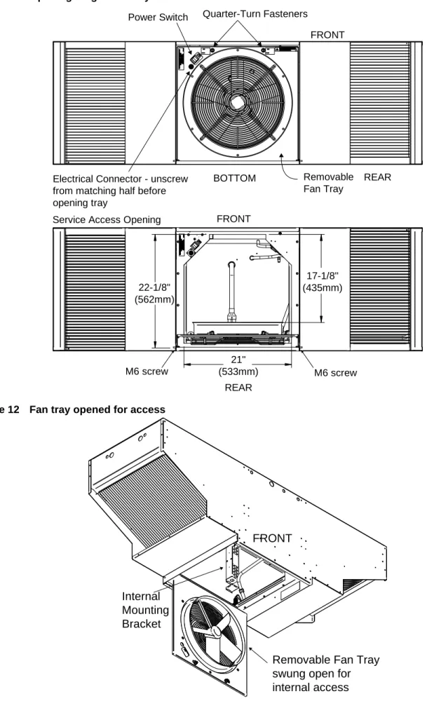
Internal Access: Opening the Fan Tray
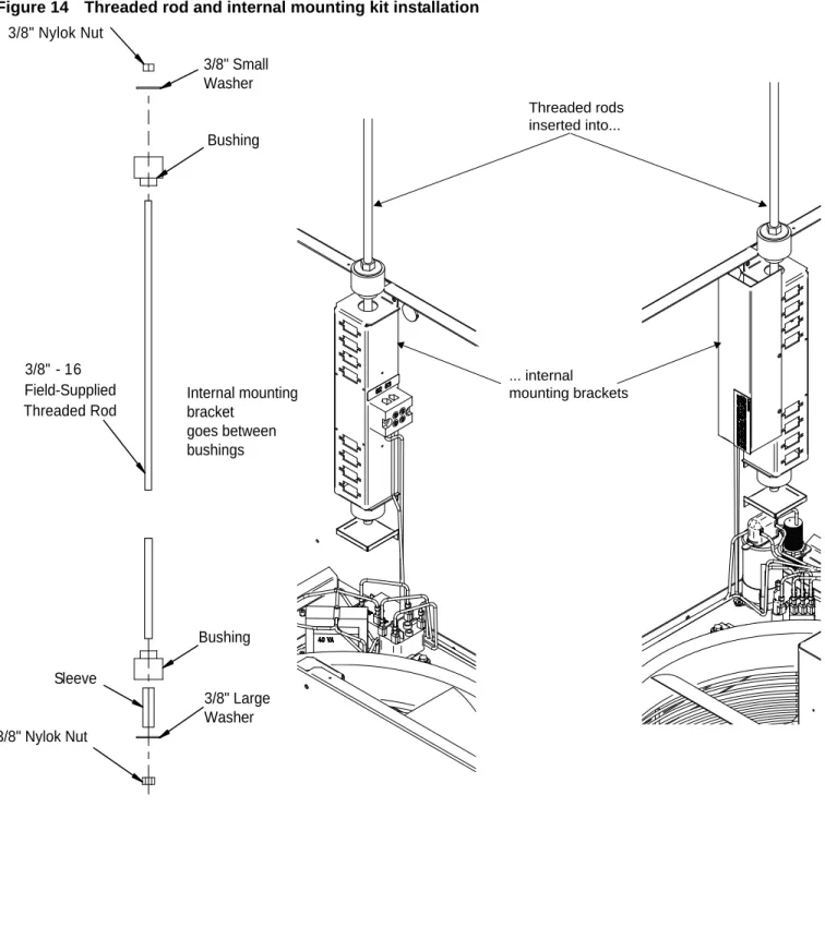
Installation With Internal Mounting Brackets
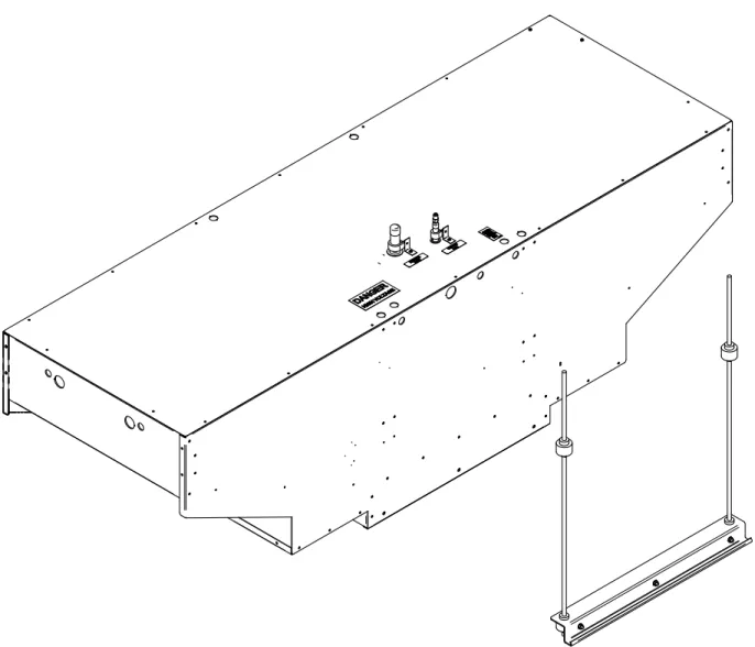
Installation With External Mounting Brackets
P IPING
The assembly and connection tools used for piping in the Liebert XD system are the same as those used in conventional refrigeration systems. For Liebert XDO with solid piping, the supply piping connection is 1/2" OD copper pipe and the return piping connection is 7/8" OD copper and will have copper caps soldered in place along with a load bearing of nitrogen. For the Liebert XDO with the pre-charged option, both the supply and return fittings are one-shot connections.
For easy connection, the hard pipe Liebert XDO provides access to supply and return pipe at the top or through the front or either side (see Figure 19). If access from a different direction is required, the factory installed pipes can be shortened and elbows installed inside the module to accommodate the alternative entrances. To reduce the possibility of condensation, insulate all pipes between the Liebert XDO and the Liebert XDP or Liebert XDC.
The Liebert XDO in hard-piped configuration is shipped with a low-pressure nitrogen charge (approximately 30 psi) to prevent oxidation and moisture. It must be vented before removing the caps at the ends of the supply and return lines. Locate the Schrader valve containing the nitrogenous charge in the Liebert XDO (see Figure 20).
Bleed the holding charge in the circuit by depressing the pin in the Schrader valve. After the charge has been bled and before soldering, wrap a wet rag around the copper terminals before removing the caps to prevent damage to the internal components. A torch can be used to remove the caps over the ends of the supply and return lines.
The mounting and connecting hardware used for piping in the Liebert XD system is similar to that used for conventional refrigeration systems. During brazing, the pipes must be filled with flowing dry nitrogen to prevent excessive oxidation and scale formation in the pipes. Current good refrigeration practice should be applied for piping support, leak testing, dehydration and filling.
Recommended Piping Size
Hard-Piped Connection Sizes
Liebert XD Piping Slope
Piping Details—Shutoff / Isolation Valves
Leak Checking and Evacuation
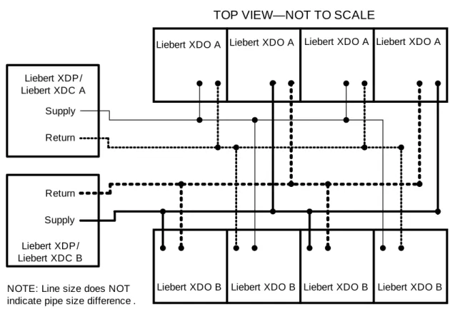
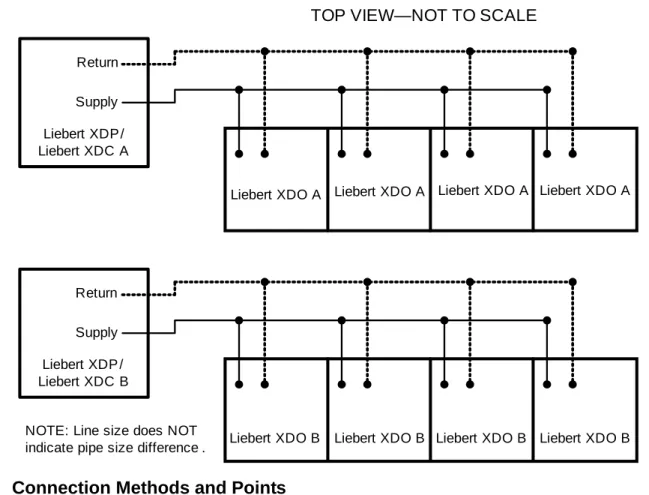
Header System
Connecting Pipes to the Top of the Liebert XDO—Hard-Piped Modules
Connecting Pipes Through the Side or Front of the Liebert XDO—Hard-Piped
Do not remove the pipe caps or plugs until the module is ready to connect to the Liebert XD Flex Pipe. The module and Liebert XD Flex Pipe contain a charge of R-134a refrigerant under pressure. Use a marker or pen to draw a line lengthwise across the Liebert XD Flex Pipe modular coupling.
Before connecting the Liebert XDO with the Liebert XD Flex Pipe to the prefabricated pipe network, check the entire system for leaks. Determine the fitting size by finding the Liebert XD Flex Pipe fitting part number. Put the Liebert XD Flex Pipe with removable couplings aside where it will not be damaged.
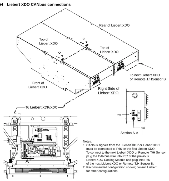
High voltage and low voltage terminals seen from the inside of the Liebert XDO. Liebert XD smart modules must be connected to Liebert XDP or Liebert XDC, which supply the modules with refrigerant. Liebert XDP and Liebert XDC have two CANbus ports (P2 and P4) each on the CAN isolator in the low voltage side of the electrical box (see figure 49).
The Liebert XDP and Liebert XDC have two CANbus ports (P2 and P4) each located on the CAN isolator on the low voltage side of the electrical box (see Figure 49). CANbus signals from the Liebert XD P or Liebert XDC must be connected to P66 on the first Liebert XDO. The Liebert XDO primary and secondary switches are also in the fan drawer (see Figure 57).
Field Installation of Liebert XD Flex Pipe Kit on Liebert XDO
Connection Method—One-Shot Connections for Pre-Charged Refrigerant Option
Do not disconnect the one-shot Liebert XD Flex Pipes after connecting them to the module. If the module includes the optional factory-installed one-shot connections, proceed to 6.15 - Field Installation of the Liebert XD Flex Pipe Kit on the Liebert XDO and see Figure 25. If the optional pre-filled option is selected, the Liebert XDO will be shipped with a full charge of R-134a pressurized refrigerant.
Do not remove the pipe caps or plugs until the module is ready to connect to Liebert XD Piping. Supply and return fittings on the preloaded Liebert XDO modules are one-shot connections.
Connect a Liebert XDO with One-Shot Couplings to Liebert XD Flex Pipe
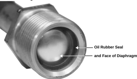
Use a small applicator brush saturated with refrigeration oil to lubricate the entire surface of the diaphragm, O-ring, and threaded portion of the male coupling. If refrigeration oil is not used, an alternative lubricant for this application is a refrigerant-compatible silicone grease product, such as Dow Corning DC200/60,000 cst. It is imperative that the brass housing on the Liebert XD Flex Pipe coupling does not rotate while the union nut is being tightened.
Hold the brass body of the Liebert XD Flex Pipe with a wrench so that it does not rotate, and use a torque wrench to tighten the union nut to the appropriate value shown in Table 3. Tighten the union nut on the Liebert XD Flex Pipe to connect to the module with the appropriate size wrench until feel a certain resistance, metal to metal contact. Tighten the nuts with another wrench straight (60°), judging the amount by the mark drawn in step 7.
Connect a Liebert XDO with Liebert XD Flex Pipe to a Liebert XD System
Apply mineral oil or polyol ester oil to the stainless steel delta ring on the male fitting (head port connector) (see Figure 31). Thread the union nut of the Liebert XD Flex tube union into the port union to ensure proper thread engagement. Using the wrench arrangement shown in Figure 32, rotate the couplings to the values in Table 4.
After the supply and return connections are complete, verify that the Liebert XDO fan breaker is off, then connect the power cable to its power source. Refer to the Liebert XDC or Liebert XDP user manual for evacuation, leak control, charging, and start-up procedures. While the Liebert XDO blower is operating, the return service valve opens first, followed by the supply service valve.

Disconnect a Liebert XD Flex Pipe from a Liebert XD System
Disconnecting the Liebert XD Flex Pipe from the Liebert XDO
Liebert XD Flex Tubes with one-shot connectors must not be removed from the Liebert XDR unless replaced with Liebert XD Flex Tubes with one-shot connectors.
Removing the Liebert XDO
E LECTRICAL C ONNECTIONS
Remote Emergency Power Off Switch Required
Connecting High-Voltage Cables—All Liebert XDO Modules
Remove two screws to remove the protective cover from the high voltage terminal block (see Figure 40 for standard Liebert XDO modules; see Figure 41 for Liebert XDO Smart modules. Connect the high voltage power supply wires and ground wire with Liebert XDO (see Figure 40 for standard Liebert XDO modules; see Figure 41 for Liebert XDO Smart modules) The black wire on the power supply line connects to L1 on the terminal block and the white wire connects to N on the terminal block.
The ground wire (earth) is connected to earth (earth) via the L1 and N connectors.

Connecting Low-Voltage Wiring—Liebert XDO Smart Modules
M OUNTING O PTIONAL L IGHT U NITS
CAN BUS L IEBERT XDP O R L IEBERT XDC I NTERCONNECTION W ITH S MART M ODULES
Network Layout Options
Remote Sensor Temperature/Humidity Sensor Placement and Connection to the
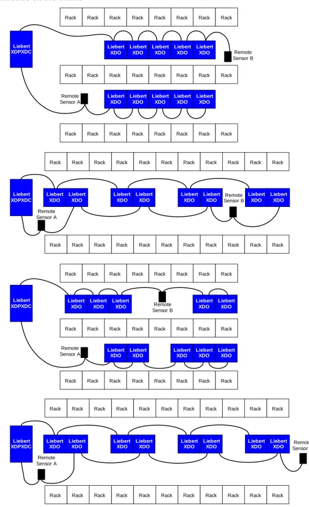
Remote sensors can be placed at the end of a chain or in the middle of a chain, as shown.
CANbus maximum length
CANbus Cables
Connecting CANbus Network
Connection to the Liebert XDP or Liebert XDC
Connecting to the Liebert XD Smart modules
CANbus Termination
Remote Temperature and Humidity Sensors Termination
If the remote sensor is the last device in the CANbus chain, no changes are necessary. If the remote sensor is not the last device in the CANbus chain, you must remove the termination jumper.
Terminating a Smart Module
Testing Network Termination
This procedure applies to the devices that are not at the end of the chain, usually a Liebert XD Smart Module. If the resistance is between 110 and 140 ohms and it is not the last control board, the device is not properly terminated. If the resistance is greater than 200 ohms and it is not the last control board, the device is not connected.
To connect to the next Liebert XDO or Remote T/H Sensor, plug the CANbus wire into P67 of the previous one. Liebert XDO cooling module and plug into P66 of the following Liebert XDO or remote T/H sensor B.
I NSTALLATION C HECKLIST AND S YSTEM F ILL FOR S TARTUP
Charging with Refrigerant and Starting the Liebert XD System
O PERATION
Start the Liebert XDO Basic Module
LED Indicators on Liebert XDO Smart Modules
Activating Remote Shutdown Option
M AINTENANCE
Fluorinated Greenhouse Gas Requirements
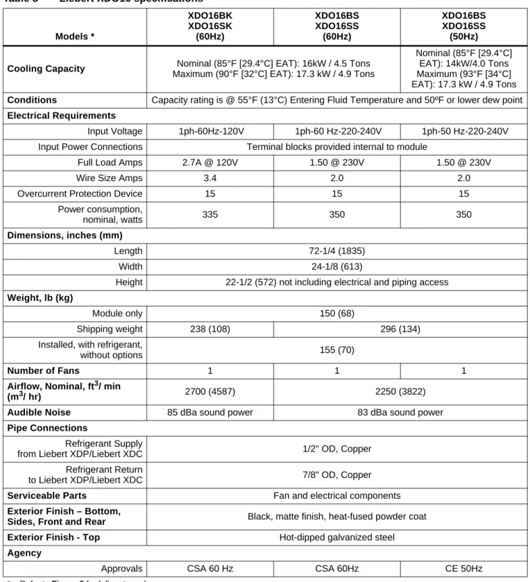
S PECIFICATIONS
Option Liebert XDO - 60 Hz models Liebert XDO - 50 Hz models Lights (included) 2 Liebert XDOs per light unit; 120V or 277V; 4' Standard Fluorescent Tubes (Not Included) Power Supply, Optional Lamp 0.9A per 120V Lamp;. factory installed).