The Liebert CRV is targeted at small and medium-sized data centers and is optimized for maximum cooling capacity with a minimal footprint. The Liebert CRV is designed to ensure proper control of room temperature, humidity and air filtration. The Liebert CRV is optimized for maximum cooling capacity in a minimal footprint and maximizes the net sensible cooling capacity used to distribute the heat load of the servers.
Consider this card only when the Liebert CRV is the only device managing humidity control in the server room. The Liebert CRV may not be able to fully meet the humidity requirements of the Liebert XD system. D Define size and number of Liebert CRV units to provide sufficient net sensible cooling capacity to meet the heat load.
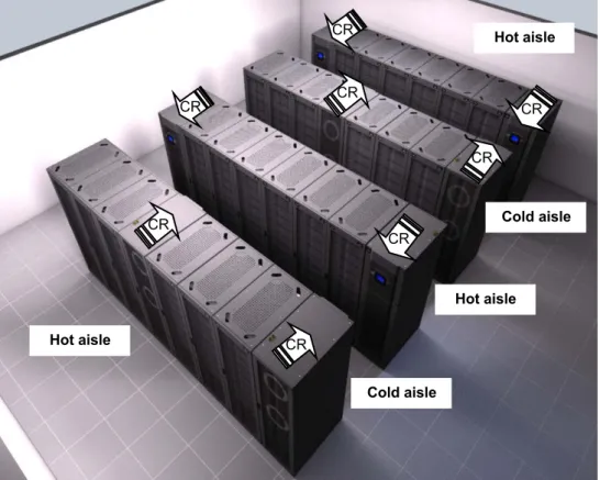
The best approach is to put the Liebert CRV at the end of the line, which results in much better air distribution. The exact number of cabinets depends on the size of the Liebert CRV unit used and the heat load per cabinet.
Application of Liebert CRV
- Solutions with redundancy
- Example of applications with CoolFlex
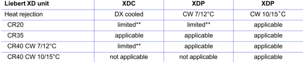
- Example of applications with Liebert XD
- Temperature sensors
Note that the number and size of Liebert CRV units must be planned to achieve the required cooling capacity should one of the units fail. When high-density IT equipment is used (typically more than 10 kW per rack) or the load distribution in rack rows is not constant and high energy efficiency is required, it is strongly recommended to use CoolFlex (cold aisle containment) together with Liebert CRV. When using high-density IT equipment (typically more than 10 kW per cabinet) with less available space, especially when a scalable solution is needed (starting with a lower thermal load and ready for future growth), the Liebert CRV together with the Liebert system is the best answer XD.
Two Liebert CRV units are used to support the Liebert XD system and provide N+1 redundancy in humidity control. It is recommended that the sensor be pointed at the front of the heat load for the most accurate temperature reading. In the InRow configuration, the temperature sensor monitors the temperature of the air entering the rack device.
The reading is used to monitor the operation of the unit, so the sensor must be positioned as indicated below, otherwise the equipment will not function properly. Insert the cabinet temperature sensor connector into the temperature sensor port on the iCom interface.
3 Liebert CRV
Standard features
FAN The unit is equipped with two plug-in fans: direct driven centrifugal fans with backward curved blades and electronically commutated DC motors; commonly called EC plug-in fans. The fan speed is variable and automatically regulated by iCOM control throughout all operating modes. The fans push air through the coil and are located on the back panel of the unit.
3-WAY MODULATING VALVE A 3-WAY modulating valve controls the water/glycol flow passing through the brazed plate condenser. The iCOM control manages the movement of the valve actuator to maintain the desired condensing temperature for different entering water flow rates and temperatures. SERVICE ACCESS All service and maintenance is performed through the front and rear of the unit.
All electrical and pipe connections are made through the top and/or bottom of the unit. CLOSE DISCONNECT SWITCH A molded case circuit breaker disrupts the flow of power to the unit.
Liebert CRV
Optional features
The pump is equipped with built-in primary and secondary float switches, pump, motor assembly and reservoir. HUMIDIFIER A humidifier with a steam tank is factory-installed in the cooling unit and controlled by the iCOM control system. It is equipped with a disposable cylinder, all inlet and outlet valves, a steam distributor and electronic controls.
An air gap in the humidifier assembly prevents backflow of the humidifier feed water. INTELLISLOT 485 BOARD (IS-485L) Provides RS-485 Modbus network connectivity to building management systems for unit monitoring and management. 2-WAY MODULATING VALVE A 2-way modulating valve controls the water/glycol flow passing through the brazed plate condenser.
2-WAY Modulating Valve A two-way modulating valve controls the flow of chilled water passing through the cooling coil. The iCOM control manages the movement of the valve actuator to provide the desired amount of cooling for different inlet water flow rates and temperatures.
Digit nomenclature
4 Operation
Cooling
Heating
Dehumidification
Humidification - optional
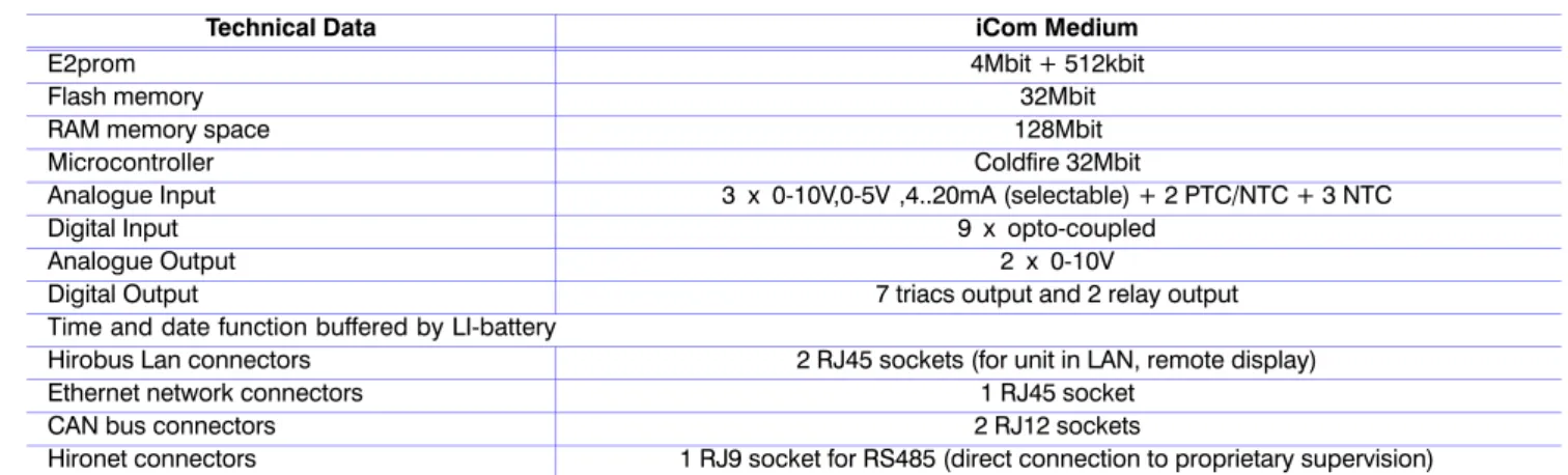
5 Microprocessor Controls
Microprocessor Controls
CDL Graphic Display (option)
6 Specifications - Air cooled
Performances - air cooled
Specifications - Air cooled
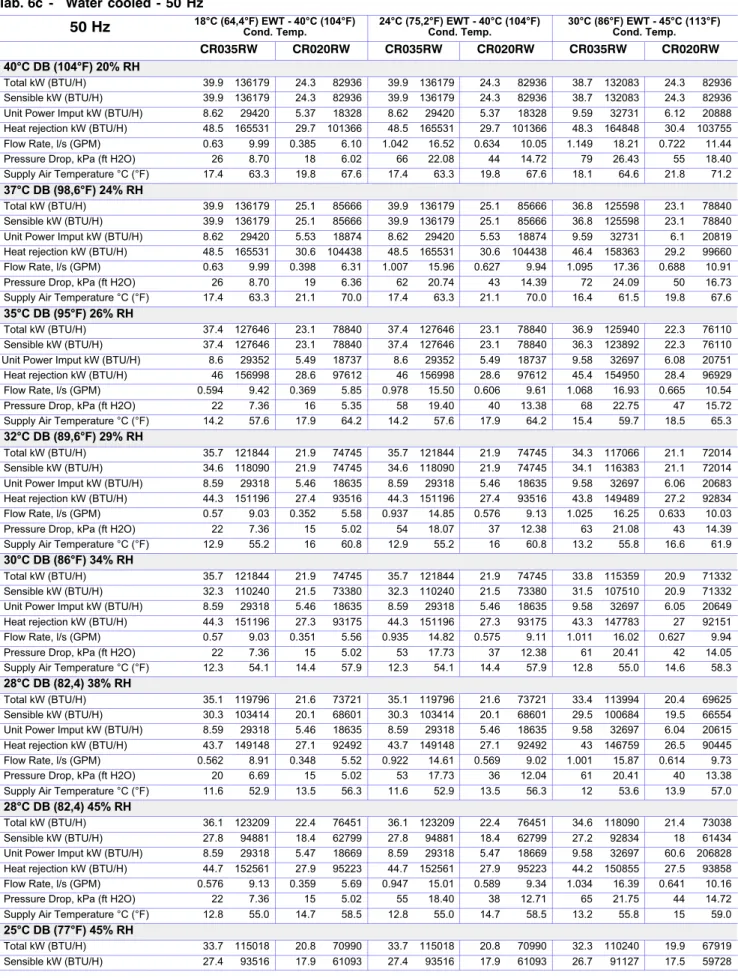
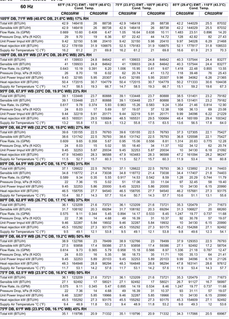
Performances - water cooled
Specifications - Water cooled
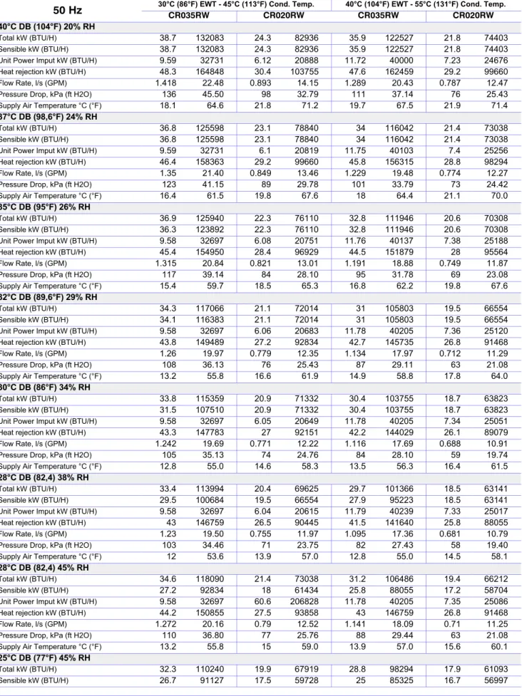
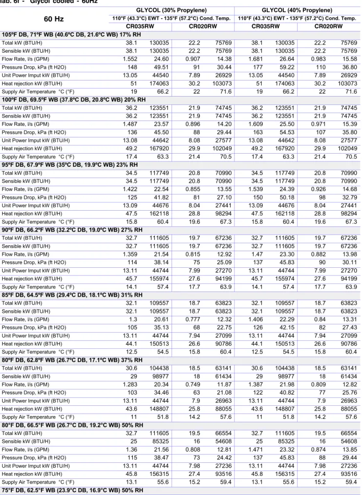
Performances - glycol cooled
Specifications - Glycol cooled
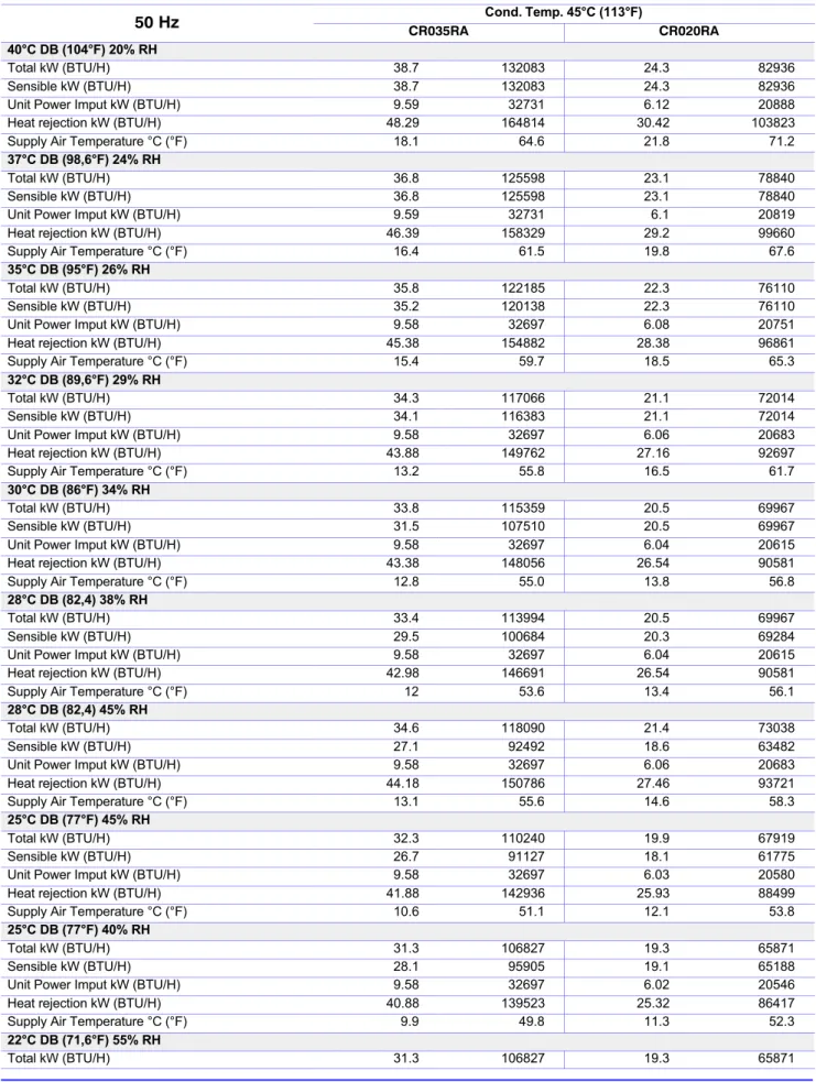
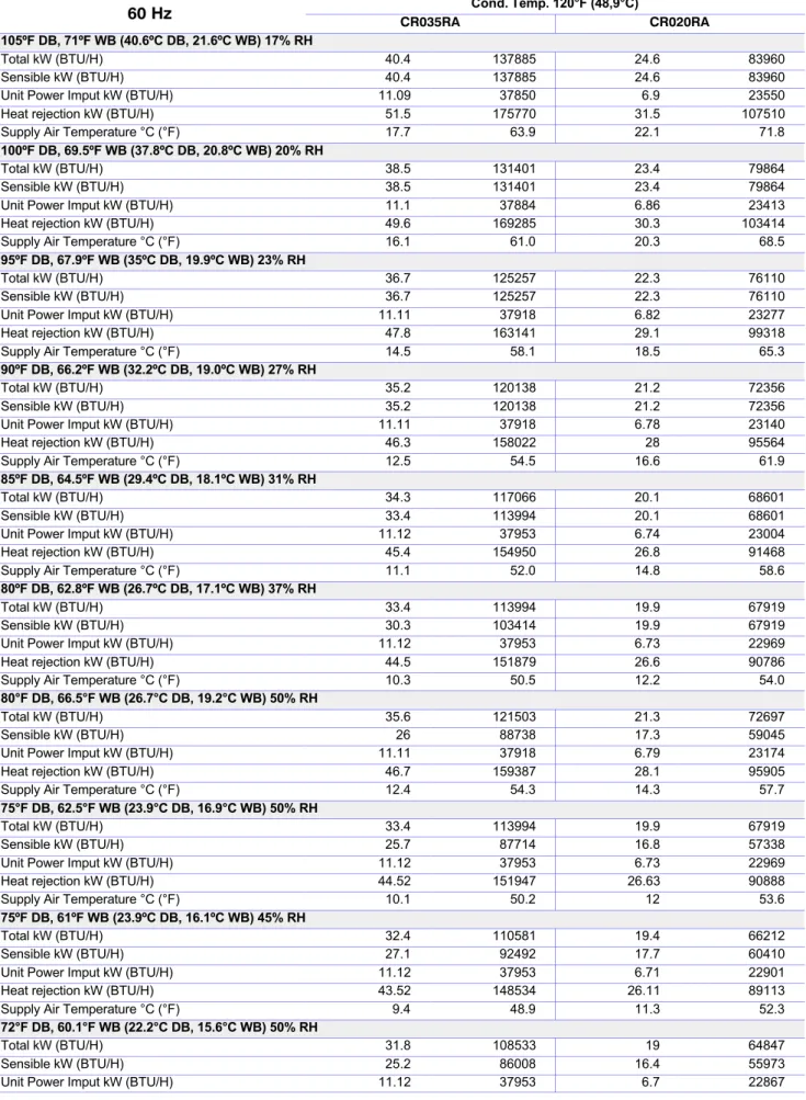
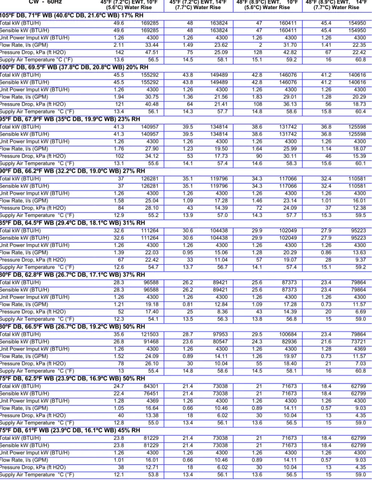
Performances - CW units
Specifications - CW
Electric data
The dimensions of the cables must be in accordance with local standards and according to the type and characteristics (e.g. amps) of the installation.
Specifications - Electrical data
Sound data
7 Heat Rejections (A version)
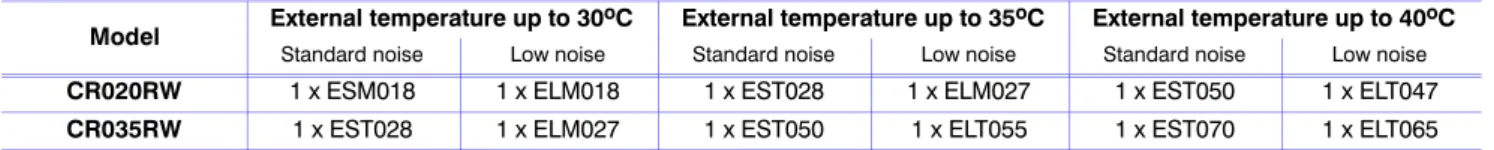
Coupling of Liebert CRV (A-type, 50Hz, CE mark) air conditioning units with remote air-cooled
D Units are factory equipped with electrical board 230V/1ph/50Hz +T, with main disconnector IP65 and with stepless fan speed controller. The electrical board is designed to allow a local or remote switch from high to low fan speed set point (and vice versa) by means of terminal contact 70---71. Sound pressure level was evaluated according to the norm EN13487, at 5m distance, with free field conditions.
Heat Rejections (W version)
Coupling of Liebert CRV (W-type, 50Hz, CE mark) water cooled air conditioning units with remote
D The axial fans are equipped with a protective net and are statically and dynamically balanced; they can guarantee high efficiency and low level of noise emission (above all in the low noise version); D Tubular heat exchanger with oval geometry that ensures better air flow and thus an increase in heat exchange efficiency, for a lower level of emitted noise. On request (optional), the unit can be ordered with aluminum fins coated with epoxy, with a better protection.
The coil manifolds are copper, with AISI 304 stainless steel flanged connections for the three-phase models and male threaded gas connections for the single-phase models. 230 V single phase 50 Hz in the ESM (standard sound level) and ELM (low sound level) models. 400 V three-phase 50 Hz in the EST (standard sound level) and ELT (low sound level) models.
D The units are equipped with an electrical protection board Q, with main switch and protection for fan motors. Sound pressure levels have been evaluated according to standard EN13487, at a distance of 10 m, with free field. 7c - Coupling of Liebert HPD drycoolers with Liebert CRV (W-type, 50Hz, CE marked) air conditioning units.
The combinations are evaluated considering a mixture of water and ethylene glycol up to 30% as the heat exchange fluid. The above indications are approximate and should be checked based on other specific operating conditions. For operating conditions other than those shown in the table, refer to the New Hirating calculation software and the Liebert HPD service manual.
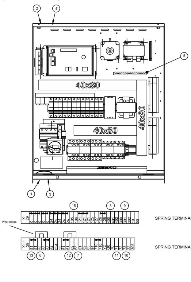
8 Installation drawings
Installation drawings
9 Refrigerant, Hydraulic and Electrical Connections
Refrigerant, Hydraulic and Electrical Connections
- Electrical field connections descriptions - 50 Hz
- Primary high voltage entrance “2.50“ (64mm); 75“ (44mm); 375” (35mm) diameter concentric knockouts located in bottom of box
- Secondary high voltage entrance “ 50“ (64mm); 1.75” (44mm); 1.375” (35mm) diameter concentric knockouts located in top of box
- Primary low voltage entrance ” Quantity (3) 1.125” (28mm) diameter knockouts located in bottom of unit
- Secondary low voltage entrance ” Quantity (3) 1.125” (28mm) diameter knockouts located in top of box
- Earth ground - Terminal for field supplied earth grounding wire
- Smoke sensor alarm (with smoke sensor option)- The smoke sensor is factory installed ,and senses the delivery air;it is connected across terminals 61-62 and send a visual and an audible
- Condensate alarm (with condensate pump option) - On pump high water indication, normally open dry contact is closed across purple wire for remote indication install inside the box near the
- Electrical field connections descriptions - 60 Hz
- High voltage entrance through the bottom of the electric panel - 38” (34.9mm), 75”
- Low voltage entrance through the bottom of the electric panel - Quantity (2) 1.125” (28mm) diameter knockouts
- Low voltage entrance through the top of the unit - Quantity (2) 1.125“ (28mm) diameter knockouts
- Three phase electrical service - Connect to terminals on disconnect switch. Three phase service not by Liebert
- Factory Installed locking Disconnect Switch
- Earth ground - Terminal for field supplied earth grounding wire
- Reheat and humidifier lockout - Remote 24VAC required at terminals 82 & 83 for lockout of reheat and humidifier
General alarm - On any alarm normally open dry contact across terminals 400,401 is closed for remote indication. Warning Alarm - On any alarm, normally open dry contact across terminals 300,301 is closed for remote indication. Compressor Motor On - On any call for compressor operation, normally open dry contact across terminals 72 & 73.2 AMP, 24VAC maximum load is closed.
The fan motor is on - at any call for fan operation, the normally open dry contact is closed via terminals 70 and 71. Smoke sensor alarm (with smoke sensor option) - a smoke sensor is factory installed and detects supply air; it is connected via terminals 61 -62 and sends a visual and sound detection of the intake air; it is connected via terminals 61-62 and sends a visual and audible alarm. This smoke sensor is not intended to operate or replace any indoor smoke detection system that may be required by local or national regulations.
Condensate Alarm (with Condensate Pump Option) - On the pump high water indicator, the normally open dry contact is closed through the purple wire for the remote indicator installation inside the box next to the dry open contact is closed through the purple wire purple for the remote indicator install inside the box next to the pump. The sensor is connected to terminals 105 and 106 and up to 5 alarm sensors can be connected. The sensor is connected to terminals 105 and 106 and up to 5 sensors can be connected to the same flood alarm device to control multiple points at the end of the unit.
Normal Alarm - On any alarm, the normally open dry contact is closed across terminals 75 and 76 for remote indication. Heat Rejection Lockout - At each call for compressor operation, the dry open contact is normally closed across terminals 70 and 71 for the heat rejection devices. Smoke Sensor Alarm - The dry factory wired contacts from the smoke sensor are 91-Common, 92-NO, and 93-NC.
Condensate alarm (with condensate pump option) - At pump high water indication, normally open dry contact is closed across terminals 88 and 89 for remote indication. Common Alarm - On each alarm, an additional normally open dry contact is closed between terminals 94 and 95 for remote indication. LiquiTect Trip and Dry Contact - On LiquiTect activation, normally open dry contact is closed across terminals 58 and 59 for remote indication (LiquiTect sensor ordered separately).
10 Refrigeration & Hydraulic Circuits
Refrigeration & Hydraulic Circuits