Be very careful when repairing or inspecting the circuit without turning off the power.
SAFETY PRECAUTION
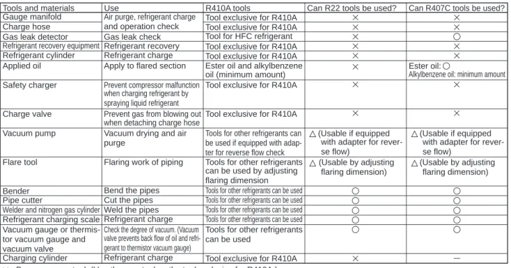
See the flow diagram below to determine if the existing pipes can be used and if a filter drier should be used. If the diameter of the existing pipes is different from the specified diameter, refer to the technical data material to confirm if the pipes can be used. Although the refrigerant piping for R410A is the same as for R22, special tools are required to prevent mixing with another type of refrigerant.
Therefore, to improve air tightness and strength, the cross-sectional dimension of the copper pipe for R410A was determined separately from the dimensions for other refrigerants, as shown below. The end nut B dimension for R410A has also been partially modified to increase strength as shown below. Exclusive tool for R410A Exclusive tool for R410A Tool for HFC refrigerant Exclusive tool for R410A Exclusive tool for R410A Ester oil and alkylbenzene oil (minimum quantity).
Tools exclusive to R410A Tools exclusive to R410A Tools for other refrigerants can be used if equipped with reverse flow control adapters Tools for other refrigerants can be used by adjusting flare dimension Tools for other refrigerants can be used tools for other coolants can be used Tools for other coolants can be used Tools for other coolants can be used Tools for other coolants can be used. Use the new tool as an exclusive tool for R410A.) : Tools for other refrigerants can be used under certain conditions.
FEATURES
SPECIFICATIONS
DATA
OUTLINES AND DIMENSIONS
WIRING DIAGRAM
Connection terminal Connection terminal Controller PCB switch
WIRING SPECIFICATIONS
If using the optional indoor power connection kit, change the wiring of the indoor unit's electrical box according to the figure on the right and the DIP switch settings on the outdoor unit's control panel. Label attached next to each indoor and outdoor unit wiring diagram Outdoor unit DIP switch settings (only when using separate indoor/outdoor unit power supplies). The indoor/outdoor unit power cords and connection cords should not be lighter than polychloroprene sheathed flexible cord.
Set the lowest number in the group for the outdoor unit whose chiller address is "00" as its M-NET address. Note: In group B, the M-NET address of the outdoor unit whose chiller address is "00" is not set to the group minimum. In A control models, the M-NET address and chiller address should be set only for the outdoor unit.
To build a central control system, the setting of M-NET address should be performed only on the outdoor unit. In the system connecting multiple outdoor units, the terminal (A, B, S) on M-NET terminal block must be wired individually to the other outdoor unit's.
REFRIGERANT SYSTEM DIAGRAM
However, this is not a problem with the product, because it is generated by the control valve itself due to a small pressure difference in the coolant circuit. If "CENTRALLY CNTROLLED" is displayed, the coolant collection (pumping down) cannot be completed normally. Press the pump-down SWP switch (push button type) on the control board of the outdoor unit.
Even if the unit is stopped and the SWP deflate switch is pressed less than 3 minutes after the compressor has stopped, refrigerant collection cannot be performed. Since the unit will automatically stop after approximately 3 minutes when refrigerant collection is completed (LED1 off, LED2 on), close the gas ball valve quickly. If refrigerant collection is completed normally (LED1 off, LED2 on), the unit will remain off until the power supply is turned off.
In this case, use refrigerant recovery equipment to collect all the refrigerant in the system. 7 Turn off the power supply (circuit breaker), remove the gauge manifold, and then disconnect the coolant pipes.
TROUBLESHOOTING
FUNCTION SETTING
2 Set the refrigerant gas addresses and indoor unit numbers with the F1 to F4 buttons, and then press the button to confirm the current setting. 5 When the settings are finished, press the button to send the setting data from the remote control to the indoor units. Note: When you enter the function selection mode in the wireless remote control operation area, the unit automatically ends the function selection mode if nothing is input for 10 minutes or more.
Function selection using the wireless remote control is only available for refrigerant systems with wireless function. Point the wireless remote controller at the receiver of the indoor unit and press the button. Point the wireless remote controller at the sensor of the indoor unit and press the button.
Start this operation from the remote control display status off.) [CHECK] lights up and flashes. Point the wireless remote control at the receiver of the indoor unit and press the button. It flashes when the remote is powering up or when there is an error.
Manual Vane Angle Use this option to set the vane angle for each vane in a fixed position. Function setting If necessary, perform the indoor unit function settings via the remote controller. Checking the remote control If the remote control does not work properly, use the check function of the remote control to solve the problem.
MONITORING THE OPERATION DATA BY THE REMOTE CONTROLLER ·93
Outdoor unit-2 phase pipe temperature (TH6) Outdoor unit-Outdoor air temperature (TH7) Outdoor unit-Heat sink temperature (TH8) Superheat discharge (SHd). Indoor unit - Liquid pipe temperature (unit no. 1) Indoor unit - Liquid pipe temperature (unit no. 2) Indoor unit - Liquid pipe temperature (unit no. 3) Indoor unit - Liquid pipe temperature (unit no. 4) Indoor unit -Cond./Eva. Indoor unit-Control status Outdoor unit-Control status Compressor-Frequency control status Outdoor unit-Fan control status Actuator output status Error content (U9).
Display of execution of replace/wash operation External unit-Microprocessor version information External unit-Microprocessor version information (sub No.). Compressor-Operating current at time of fault Compressor-Accumulated operating time at time of fault Compressor-Number of operating times at time of fault Discharge temperature (TH4) or comp. Outdoor unit-2-phase pipe temperature (TH6) at the time of fault Outdoor unit-Outdoor temperature (TH7) at the time of fault Outdoor unit-Heatsink temperature (TH8) at the time of fault Discharge superheat (SHd) at the time of fault.
Inside -Liquid pipe temperature at time of fault Inside -Cond/Eva. pipe temperature at time of fault Inside at time of fault. Indoor unit-Capacity setting information Indoor unit-SW3 information. indoor control board side) setting Indoor unit-SW5 information. Maintenance data, such as indoor/outdoor unit heat exchanger temperature and compressor operating current can be displayed with "Smooth Maintenance".
Compressor Outdoor unit Indoor unit Accumulated working Heat exchanger 7 Inlet air time (o10 hours) temperature (:) temperature. 4 Coolant/heat exchanger temperature COOLING : HEAT : 5 Coolant/discharge temperature COOLING : HEAT : 6 Air/outdoor temperature COOLING : HEAT : (Air/exhaust temperature) COOLING : HEAT. Air/inlet air temperature COOLING : HEAT : (Air/discharge temperature) COOLING : HEAT : 8. Coolant/heat exchanger temperature COOLING : HEAT.
7 Indoor intake air temperature) – (8 Indoor heat exchanger temperature) Is “D000” displayed steadily on the remote control. In heat mode, the operating condition may change due to the formation of frost on the external heat exchanger. 7 Indoor intake air temperature)— (8 Indoor heat exchanger temperature) (8 Indoor heat exchanger temperature) — (7 Indoor intake air temperature) [5 Exhaust temperature] – [4 External heat exchanger temperature).
DISASSEMBLY PROCEDURE
Removing the service panel and top panel. 1) Remove the service panel mounting screws (4 for front/5 x 12), then slide the service panel down to remove it. See Figure 4 or 5) (4) Undo the lead wire clip in the electrical parts box. See procedure no. 5 on the previous page to remove the thermistor <2-phase tube> (TH6).
To remove the reactor, the electrical parts box must be separated from the outdoor unit.). To remove the thermistor
