Outdoor Unit
Indoor Unit
Overload protection, when the compressor current is higher than the normal level, the compressor stops and the unit displays a fault code. Reverse (open) phase protection, when the phase sequence of the supply is inconsistent or the phase is absent, the unit cannot work and display a fault code.
Product Data at Rated Condition
Ĺ Noise is tested in the Semianechoic Room, so it should be a little higher in actual operation due to environmental changes. Ĺ Noise is tested in the Semianechoic room, so it should be slightly higher in actual operation due to environmental changes.
Operation Range
Electrical Data
Cooling/Dry Operation
Heating Operation
Cooling
Dry Mode
Heating Mode
Defrosting
Fan Mode
Operation View
4 ON/OFF button Press the button to set start or close unit 5 LCD screen Display the status of remote control information 6 Fan speed button Press this button to set fan speed 7 Sleep button Press the button to set sleep function 8 Time on Press the button to set time on function 9 Time off Press the button to set time off function.
Display View
Operation View
5 Sleep/SWING button Press the button to set the sleep/swing function 6 Timer button Press the button to set the timer function 7 On/off button Press the button to set the start or shutdown of the device 8 Remote control window Get remote information. 1˅ SAVE setup ˖When the unit is off, to press “FAN” +“ź” buttons continuously for 5 seconds, it can enter into saved setup interphase, the unit will run in save mode. When the unit is off, press the "FAN" button for 5 seconds and set up the fresh air setup.
3˅ Outdoor ambient temperature display: Under normal mode, "ENV" will show the room temperature, when the unit is on or the unit is off, press the "SLEEP/SWING" button last for 5 seconds, the LCD will show "OUT ENV". 4˅ MEMORY function setting: When the device is off, press the "MODE" button for 10 seconds to switch the device's mode on or off after it is off. 5˅ Troubleshooting function: When the device is off, continuously press the “FAN” + “SLEEP” buttons lasting 10 seconds, call up the debugging menu and show “Debugging” icons, use the “MODE” button adjust the setting item by pressing “Ÿ”ǃ “ź” button to set the detailed value.
Display View
Dimension
Installation
The communication distance between the main board and the wire controller can be as far as 20m (The standard distance is 8m). The wire controller must not be installed in a place where there is waterfall or large amount of water vapor.

Centralized Controller-not with week timer
Centralized Controller-week timer
3 Decrease key Press " " and select the unit or a specific day in a week or a specific value. 2 Group operation displays when group operation is displayed 3 Single operation displays when single unit operation is displayed 4 Timer time in week views Display time in week. 8 on control displays When the unit or group is on, shows, 9 off control displays When the unit or group is off, shows, 10 current time in week view Show current time of the week.
11 current time in Hr:Min displays Display time of hour and minute now 12 timer off time displays Display in time.
Field Setting
Control Wiring Design
Installation of Duct Type
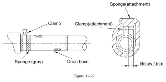
The joints of the drainage pipeline must be covered with heat-insulating materials to prevent the formation of external condensate. Air supply pipes and air supply pipes are attached to the ceiling mounting plates using an insulating layer of condensate pipes. Pipe joints must be sealed with glue to prevent leakage.
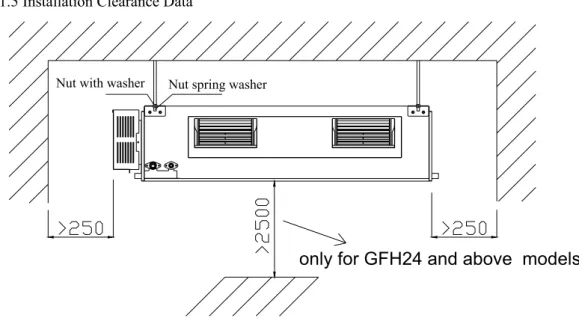
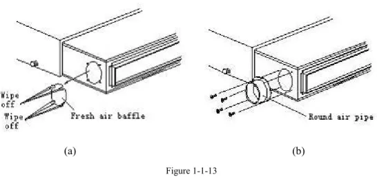
The edge of the air intake pipe must be at least 150 mm away from the wall. Silence and shock absorption must be considered in the design and installation of air ducts. If the fresh air duct is not used, the gaps around the battle should be closed with sponge.
Factory square flanges should be installed at the rear as standard, and the air return deck plate should be installed at the bottom, as shown in Figure 1-1-14. The air return duct must be connected to the air return inlet of the indoor unit with rivets, and the other end of the air return duct must be connected to an air return window.
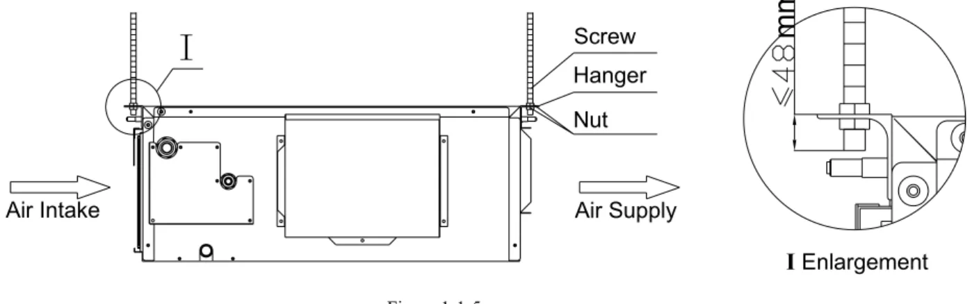
Installation of Ceiling Type
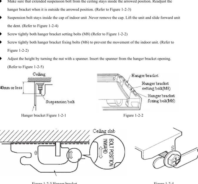
Do not use the device in the immediate vicinity of a laundry, bath, shower or swimming pool. Tighten both bracket mounting bolts (M6) to prevent movement of the indoor unit. It is possible to install using inward facing hanger brackets without removing the brackets from the indoor unit.
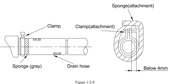
A drain plug is located on the left and right side of the indoor unit. When connecting the drain pipe to the unit, do not apply excessive force to the pipe on the side of the unit. When making the connection, place the end of the PVC pipe in the drain hole.
If the unit is installed in a new house, carry out tests before decorating the ceiling. The diameter of the discharge pipe must be equal to or greater than the diameter of the connection pipe.
Installation of Cassette Type
Before Installation
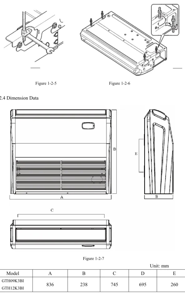
Dimension Data
Installation Clearance Data
Install the installation card on the bolt unit (3 pieces) and adjust the angle of the drain pipe to the bolt outlet. The diameter of the drain hose must be equal to or larger than that of the connecting pipe. To prevent bending of the drain hose, the distance between the lifting stand should be 1 to 1.5 m.
The characteristics of the discharge hose of the selected coupling must be adapted to the operating capacity of the unit. Upon receipt of the machine, the unit and accessories will be checked in accordance with the packing list. Make sure there is no obstruction to the air intake and exhaust of the outdoor unit.
When installing the drain pipe, the connection of the drain pipe must be placed in a drain hole on the chassis of the outdoor unit. If the drain connection is used, the installation height of the outdoor unit must be at least 5 cm).
Refrigeration Piping Work Procedures
Connect the vacuum gauge tubing to the vacuum pump, with the low pressure end connecting to the refrigerant inlet. Detach the pipe from the coolant inlet cap, then tighten the cap. . . Loosen the valve cord on the gas valve as well as the liquid valve completely. Tighten the valve cap on the gas valve and liquid valve to check for leaks.
To prevent condensation on the connecting pipe and prevent leakage, the large pipe and the small pipe of the connecting pipe should be covered with heat-insulating materials, connected with adhesive tape, and isolated from the air. There should be no gap between the joint of the connecting pipe and the wall of the indoor unit. To prevent condensate from flowing out of the drain pipe, separate the drain pipe from the connecting pipe and cables.
Use thermal insulation tape to wrap the pipes from the bottom of the outdoor unit up to the top end of the pipe where the pipe enters the wall. When wrapping thermal insulation tape, the later tape circle must cover half of the front tape circle (Figure 3-1-7).
Caution in Connecting Pipes
When pipes are wrapped with protective materials, never bend them to form a very small angle, otherwise the pipes may crack or break. Do not wrap the protective tape too tightly, otherwise the effectiveness of the thermal insulation may be reduced. After the protective work is completed and the pipes are wrapped, seal the hole in the wall with sealing material to prevent rain and wind from entering the room.
Refer to the following table for how much refrigerant must be added for each meter extension. If the height difference between the indoor unit and the outdoor unit exceeds 10m when installing the air conditioning system, an oil return bend must be fitted with an interval of 6m. If the heights of the indoor unit and the outdoor unit are different, the pipes must be laid out with reference to figure 3-2-1.
Specification of Connection Pipe
Wiring Principle
Ĺ Utility pliers to bend the end of the single wire to form a loop that matches the screw size. Ĺ Use a crimping tool to connect a terminal (matching the size of the screw) to the end of the multiple twisted wires. If the flexible power supply line or the signal line of the equipment is damaged, only use a special flexible line to replace it.
If several twisted wires are connected to the terminal board, an arc may occur. . . All line connections must conform to the schematic diagram of lines. For air conditioning with booster heater, it is required to connect the power cable to the "L1, L2 L3" terminals and the ground screw. Be extremely careful when making the following connections to avoid malfunction of the air conditioner due to electromagnetic interference.
The signal line of the wired controller must be separated from the power line and. Connect the signal line of the wired controller to the 4-bit socket on the indoor unit PCB.
Electric Wiring Design
Specification of Power Supply Wire and Air Switch
If the compressor overload switch is tripped after starting the compressor, an error is reported. All loads (except the four-way valve) are switched off, an error is displayed and the compressor stops for 3 minutes. The compressor and the outdoor unit will stop, and the four-way valve will stop 2 minutes after the compressor stops in the heating state.
The water level is detected continuously for 8 seconds after the system is turned on, the water level protection is triggered and the indicator flashes (or E9 is displayed). In the air supply mode, only an error is displayed and the indoor unit operates normally. After starting the compressor, an open circuit of the heat lamp on the discharge is detected for a continuous 5 seconds.
After the error is removed, the system will reset itself and clear the error code. In air supply mode, only the error is displayed and the indoor fan runs normally.
Wiring Diagram-Outdoor Units
Wiring Diagram-Indoor units
Outdoor Unit
Indoor Unit
Outdoor Unit
Indoor Unit