SAFETY PRECAUTION
Although the refrigerant piping for R410A is the same as for R22, exclusive tools are required to avoid mixing different types of refrigerants. Because the working pressure of R410A is 1.6 times higher than that of R22, the dimensions of the flared sections and flare nuts are different. Since the working pressure of R410A is higher than that of R22, use refrigerant pipes with the thickness specified below.
Therefore, to increase the air tightness and intensity, the cross-sectional dimension of the copper pipe for R410A was determined separately from the dimensions for other refrigerants, as shown below. The B end nut dimension for R410A has also been partially modified to increase the intensity as shown below. Exclusive tool for R410A Exclusive tool for R410A Tool for HFC refrigerant Exclusive tool for R410A Exclusive tool for R410A Ester oil and alkylbenzene oil (minimum quantity).
Tools exclusive to R410A Tools exclusive to R410A Tools for other refrigerants can be used if equipped with reverse flow control adapters Tools for other refrigerants can be used by adjusting flare dimension Tools for other refrigerants can be used tools for other coolants can be used Tools for other coolants can be used Tools for other coolants can be used Tools for other coolants can be used. Use the new tool as an exclusive tool for R410A.) : Tools for other refrigerants can be used under certain conditions.

OVERVIEW OF UNITS
The additional connection of the Branch Box together with the use of the compact trunk-view outdoor unit can successfully realize a long-distance pipeline for large houses. Equipped with a microprocessor, the Branch Box can translate the indoor units' transmission signal to achieve optimal control. Junction box (Controller) Number of branches 5 : 5 branches 3 : 3 branches Model type Factory symbol Applicable refrigerant A : R410A.
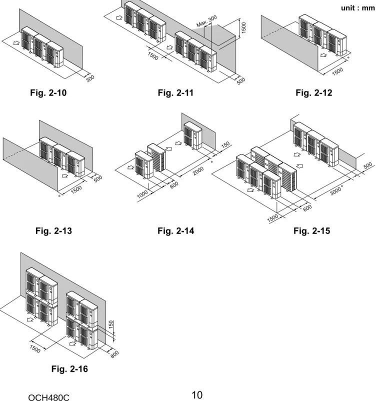
When using an optional air outlet guide installed for upward airflow, the distance is 1000 mm or more. When using an optional air outlet guide installed for upward airflow, the distance is 1500 mm or more. If the pipe connection size of the junction box does not match the pipe connection size of the indoor unit, use optional joints of different diameter (deform) for the side of the junction box. Connect deformed joint directly to junction box side.).
For P100 indoor units, the individual Y-shaped connection pipes use 2 ports on the junction box as shown below. To connect two P100 indoor units, use port A and port B and port C and port D on the junction box.
SPECIFICATIONS
To obtain the system cooling and heating capacity and the electrical characteristics of the outdoor unit, first add up the ratings of all the indoor units connected to the outdoor unit (see table below), then use this total to calculate the standard capacity with the help of the tables at the back of the manual "INNER UNITS COMBINATION SHEETS". Therefore, the capacity of MSZ-EF25VE and PEAD-RP50JAQ will be calculated as follows using the formula in 4-1-2. Therefore, the capacity of MSZ-EF25VE and PEAD-RP50JAQ will be calculated as follows using the formula in 4-1-2.
1 System composed of indoor and outdoor unit (in this example, the total capacity of the indoor units is greater than that of the outdoor unit). 3 The following figures are from the 150 unit total capacity row of the standard capacity chart (INDOOR UNITS COMBINATION SHEET: at the back of the manual).
DATA
Use the rated capacity and rated power values listed in the characteristics table for each indoor unit. To obtain the total capacity, the capacity on the sides of each indoor unit must be added. Individual capacity at the rated time Individual capacity under stated conditions =Total capacity under the stated conditions o.
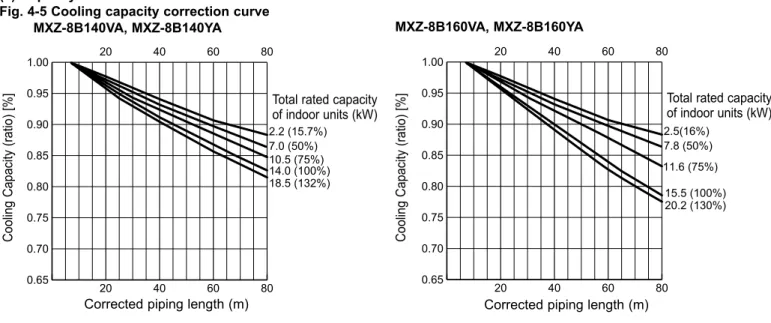
Wet bulb temperature of the outdoor air intake air <:W.B.> Wet bulb temperature of the outdoor air intake air <:W.B.>. Indoor inlet air wet bulb temperature <:W.B.> Indoor inlet air wet bulb temperature <:W.B.>. To obtain the ratio (and corrected piping length) of the rated capacity of the outdoor units and the total indoor capacity during use, first find the capacity ratio corresponding to the standard piping length shown in Fig. 4.
-6 and then multiply by the capacity from fig. 2) Method to obtain the corrected pipe length.
OUTLINES AND DIMENSIONS
WIRING DIAGRAM
WARNING: When the main supply is disconnected, the voltage [540 V] in the main capacitor will drop to 20 V in approx. 5 minutes (input voltage: 380 V). Components other than the outer plate may be defective: check and take corrective action according to the service manual. Junction box/outdoor communication error (Signal reception error)(Outdoor unit) Indoor/junction box communication error (Signal reception error)(Junction box) Junction box/outdoor communication error (Transmitting error)(Outdoor unit) Indoor/junction box communication error (Transmission error)(Junction box).
Misconnection of connection wire to indoor junction box/junction box outdoor unit (reversed wiring or disconnection) Start time over. Radiator panel temperature error Outdoor fan motor abnormality Voltage error, current sensor error Forced compressor stop. Overlap failure of drain pump in indoor unit and linear expansion valve in junction box) MODEL.
NECESSARY CONDITIONS FOR SYSTEM CONSTRUCTION
When using the indoor unit type 35, 50 P series, use the end nut (for R410A) attached to the indoor unit. Use the refrigerant pipes listed in the table below to connect the P100 indoor unit. Liquid pipe Gas pipe Liquid pipe Gas pipe Liquid pipe Gas pipe Liquid pipe Gas pipe Liquid pipe Gas pipe.
When using 60 type indoor unit of MEXZ series, use the flare nut in the indoor unit accessory for the gas side connection of indoor unit.
TROUBLESHOOTING
ELECTRICAL WIRING
Outdoor/junction box controller circuit can automatically set the unit number of indoor units. To connect the P100 indoor unit(s), the connection cable(s) must be connected to the specified terminal block(s) in the junction box. P100 indoor unit(s) are not connected to the specified terminal block(s) in the junction box.
The connection wires from the P100 indoor unit are connected to the wrong terminal blocks in the distribution box. Abnormal if the junction box/external controller circuit could not receive anything for normal 3 minutes. Incorrect wiring of connecting wire indoor - distribution box/junction box - outdoor unit (converse wiring or disconnection) Startup time has expired.
WIRING SPECIFICATIONS
OC : Outdoor unit BC : Junction box IC : Indoor unit RC : Remote control BC (5-branch type).
SYSTEM CONTROL
REFRIGERANT PIPING TASK
If connecting an indoor unit with :9.52 liquid piping (model number 71 or more for M and S series and model number 60 or more for P series), the additional refrigerant charge amount in Table 1 must be corrected (add the following to R- value of the value given in Table 1). Because indoor units are connected with :9.52 liquid pipes (indoor units A and D in this example), the additional refrigerant charge amount must be corrected. Although two ø6.35 liquid pipes are used between the junction box and the Y-shape connection pipe when connecting the P100 indoor unit, calculate the additional refrigerant charge amount assuming that only one ø9.52 liquid pipe is used.
Perform the following procedures to collect the refrigerant when moving the indoor unit or outdoor unit. 2 Connect the low pressure side of the gauge manifold to the service port of the gas side shutoff valve. Indoor-outdoor communication start-up takes approximately 3 minutes after the power (circuit breaker) is turned on.
Start pump discharge operation 3 to 4 minutes after power (switch) is turned on. However, even if the unit stops and SW4-1 and SW4-2 are set to ON less than 3 minutes after the compressor stops, the refrigerant collection operation cannot be performed. If this happens, use a refrigerant collection device to collect all the refrigerant in the system and then recharge the system with the correct amount of refrigerant after the indoor and outdoor units have been moved.
The compressor may burst if air, etc. situation in which there are no doorways or in which there are openings above and below doors that occupy at least 0.15% of the floor area). R410A refrigerant of this air conditioner is non-toxic and non-flammable, but leakage of large quantities from an indoor unit into the room where the unit is installed can be harmful. Total amount of refrigerant is pre-charged refrigerant at ex-factory plus additional charge amount at field installation.
The section with represents the room with the smallest volume. a) Situation where there are no partitions. All the refrigerant from this system will leak into this room if there is a leak from this indoor unit. To facilitate calculation, the maximum concentration is expressed in units of O/K (kg R410A per K). KHK installation guidelines S0010) Maximum concentration of R410A: 0.3O/K.
DISASSEMBLY PROCEDURE
Note: In case of replacing the thermistor