Guidance Manual for Constructed Wetlands
R&D Technical Report P2-159/TR2
J. B. Ellis, R.B.E. Shutes and D.M. Revitt
Research Contractor:
Urban Pollution Research Centre
Middlesex University, London
Publishing Organisation
Environment Agency, Rio House, Waterside Drive, Aztec West, Almondsbury, BRISTOL, BS32 4UD
Tel: 01454 624400 Fax: 01454 624409 Website: www.environment-agency.gov.uk
© Environment Agency 2003 ISBN 1 844 321185
All rights reserved. No part of this document may be reproduced, stored in a retrieval system, or transmitted, in any form or by any means, electronic, mechanical, photocopying, recording or otherwise without the prior permission of the Environment Agency.
The views expressed in this document are not necessarily those of the Environment Agency. Its officers, servants or agents accept no liability whatsoever for any loss or damage arising from the interpretation or use of the information, or reliance upon views contained herein.
Dissemination Status
Internal: Released to Regions External: Released to Public Domain Statement of Use
This Guidance Manual is for use by Environment Agency operational staff and others involved in the control and management of surface water runoff from development, and those who are seeking advice on the construction and operation of constructed wetlands to treat road runoff.
Keywords
Constructed wetlands, reedbeds, urban stormwater runoff, urban runoff quality control, sustainable drainage systems (SuDS), urban catchment management, decision support systems, multicriteria assessment.
Research Contractor
This document was produced under R&D Project P2-159 by:
Urban Pollution Research Centre, Middlesex University, Bounds Green Road, London, N11 2NQ Tel: 02 08 411 5000 Fax: 02 08 411 6580 Website:
www.mdx.ac.uk
Environment Agency’s Project Managers
The Environment Agency’s Project Managers for Project P2-159 were:
Dr Maxine Forshaw, National Centre for Ecotoxicology & Hazardous Substances Barry Winter and Doug Mills, Thames Region
CONTENTS
Page
ABBREVIATIONS vii
GLOSSARY x
EXECUTIVE SUMMARY xiii
1. INTRODUCTION 1
1.1 Background and Context 1
1.2 Aim of this Guidance Manual 1
1.3 Wetland Types and Definitions 2
1.4 Constructed Wetlands and Flow Systems 5
1.5 Pocket or Mini-Wetlands 8
1.6 Modular or Treatment-Train Systems 9
1.7 How Wetlands Work 9
1.8 Wetland Classification 13
2. WETLAND DESIGN 15
2.1 Introduction 15
2.2 Design Criteria 16
2.3 Substrate Structure 24
2.4 Planting Considerations 25
2.5 Pre and Post Treatment Structures 27
2.6 Wetland retrofitting 30
3. WETLAND PERFORMANCE AND COSTS 35
3.1 Wetland Performance 35
3.2 Performance Indicators 40
3.3 Treatment, Performance and maintenance Costs 42
4. OPERATION AND MAINTENANCE 47 4.1 Wetland Operation and Maintenance Requirements 47
5. WILDLIFE AND LANDSCAPE ENHANCEMENT 53
5.1 Multifunctional Use of Urban Wetlands 53
5.2 Landscape and Visual Issues 53
5.3 Landscape Development 54
5.4 Wetland Wildlife Considerations 56
6. SUDS IMPLEMENTATION AND CATCHMENT
PLANNING 59
6.1 Introduction; The Need for Integrated Approaches 59
6.2 SuDS and the EU Water Framework Directive 59
6.3 Implementing SuDS within River Basin
Management Planning 61
7. DECISION SUPPORT APPROACHES 63 7.1 Introduction: Towards a Multi-Criteria Approach 63 7.2 Defining Primary Criteria, Indicators and Benchmarks 63
7.3 Applying a Multi-Criteria Approach 63
7.4 Benchmark Indicator Standards 63
7.5 Matrix Approaches 66
7.6 Wetland Design Procedure 66
8. RECOMMENDATIONS FOR FURTHER RESEARCH 68
KEY DOCUMENTS 70
APPENDICES
Appendix A Wetland Processes 72
Appendix B Wetland Pollutant Efficiency Rates 77
Appendix C Kinetic Design Modelling of Wetlands 80
Appendix D Surface Water Discharges, Sediment Quality Standards and
Receiving Water Classification in England & Wales 84 Appendix E Outline Inspection Sheet: Wetland Operation,
Maintenance & Management 89
List of Tables
Table 1.1a Wetland Pollutant Removal Mechanisms and their Major
Controlling Factors 11
Table 1.1b Relative Importance of Wetland Pollutant Removal Mechanisms 11 Table 1.2 A Process-based Classification of Constructed Wetlands 14 Table 2.1 Plant Species Commonly Used in Constructed Wetlands 26 Table 2.2 Summary of the Main Methods Used to Establish the Common Reed
(Phragmites australis) 27
Table 3.1 Percentage Pollutant Removals for Domestic Wastewater and
Artificial Stormwater Wetland Systems in the UK 35 Table 3.2 Wetland Metal Removal Efficiencies for Natural and Artificial
Wetlands in the UK 37
Table 3.3 SuDS Pollutant Removal and Flow Attenuation Capacities 41 Table 3.4 Wetland and Dry/Wet Storage Basin Indicators 40
Table 3.5 Distribution of Wetland Capital Costs 43
Table 3.6 Capital and Maintenance Costs for Highway Treatment Systems 44 Table 7.1 Sustainability Criteria and Indicators for Urban Wetlands and SuDS 64
Table 7.2 SuDS Technology Evaluation Matrix 66
Table Appendix B1 Solid Sizes and Settling Velocities 77 Table Appendix B2 Pollutant Load Fractions Attached to Stormwater Solids 78 Table Appendix D1 Standards for Intermittent Discharges 85 Table Appendix D2 Fundamental Intermittent Standards for Ecosystem Types 86 Table Appendix D3 Pollutant 99 Percentile Values for RE Classes 86
Table Appendix D4 Sediment Quality Standards 88
List of Figures
Figure ES1 Major components of On-Line Constructed Wetland xv Figure ES2 Major components of Off-Line Constructed Wetland xvi
Figure 1.1a SF Constructed Wetland Design 6
Figure 1.1b SF Constructed Wetland Illustrative Cross-section 7
Figure 1.2a A SSF Constructed Wetland 8
Figure 1.2b A SSF Constructed wetland Illustrative Cross-section 8 Figure 1.3 Nitrogen Transformation in a Wetland System 10 Figure 2.1 Linkages and Interactions between Wetland Design Elements 17
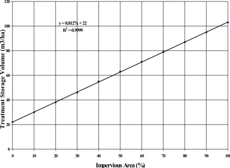
Figure 2.2 Wetland Treatment Storage Volumes 20
Figure 2.3 Section through a Sub-surface Constructed Wetland 22 Figure 2.4 Idealised layout of a Constructed Wetland 29 Figure 2.5 Original On-stream Wet Retention Balancing Pond before Retrofitting 32 Figure 2.6 Flood Balancing Pond Following Retrofitting to Incorporate a
Constructed Wetland 32
Figure 2.7 Section Through Retrofitted Constructed Wetland 33 Figure 2.8 Retrofitting a Dual Outlet to a Flood Storage Pond 34
Figure 3.1 SSF Wetland Performance Costs 42
Figure 4.1 Predicting Sediment Removal Maintenance Requirement Time 48 Figure 5.1 Schematic Landscaping for a Wet Retention and Wetland Basin 55 Figure 5.2 The Great Notley Garden Village Wetland 56
Figure 6.1 RBMP Programme of Measures 60
Figure 7.1 Multi-Criteria Analysis for the Evaluation of Urban Runoff Control
and Treatment Options 65
Figure 7.2 Process Diagram for the Design of Constructed Wetlands 67
Figure Appendix A1 Solids Retention Under Differing Discharge
and Volume Conditions 72
Figure Appendix A2 Solids Retention Curves for Three Wetland Sites 73 Figure Appendix C1 Bacterial Removal Efficiency and Hydraulic Loading Rate 83
Figure Appendix D1 Water Quality Assessment Schemes 89
List of Plates
Plate 1 View of Pond F/G looking towards the outlet, with the A34 (Newbury Bypass) in the background. Retro fitted sub-surface flow wetland and balancing
pond. xviii
Plate 2 Overview of Pond B looking towards the inlet, alongside the A34
(Newbury Bypass). Surface flow constructed wetland and balancing pond. xviii Plate 3 A constructed wetland within a commercial development in Milton
Keynes, providing flood storage, pollutant treatment and aesthetic amenity
value. xix
Plate 4 Vegetated balancing pond at Aztec West Business Park, near Bristol,
with ecological features and aeration. xix
ABBREVIATIONS
AMP Asset Management Plan ASPT Average Score Per Taxon
AONB Area of Outstanding Natural Beauty
BAP Biodiversity Action Plan
BMWP Biological Monitoring Working Party
BOD Biochemical Oxygen Demand
BMP Best Management Practice
BPEO Best Practicable Environmental Option
CESM3 Civil Engineering Standard Method of Measurement
CIRIA Construction Industry Research & Information Association
COD Chemical Oxygen Demand
CSO Combined Sewer Overflow
CW Constructed Wetland
DEFRA Department of Environment, Food and Rural Affairs DETR Department of Environment, Transport and the Regions
DO Dissolved Oxygen
DTLR Department of Transport, Local Government and Regions
ED Extended Detention Basin
EMC Event Mean Concentration EIA Environmental Impact Analysis
EPSRC Engineering and Physical Sciences Research Council
EQI Environmental Quality Index
EQS Environmental Quality Standard FWR Foundation for Water Research
GQA General Quality Assessment HLR Hydraulic Loading Rate HRT Hydraulic Retention Time
IPPC Integrated Pollution Prevention and Control IRBM Integrated River Basin Management
LCP Local Contribution Plans
LEAP Local Environment Agency Plan
LNR Local Nature Reserve
MIPS Material Intensity per Service Unit MTBE Methyl Tertiary Butyl Ether
NGO Non-Government Organisation
NNR National Nature Reserve
NOEC No Observable Effect Concentration
NWC National Water Council
O&M Operation & Maintenance OFWAT Office of Water Services PAH Poly-Aromatic Hydrocarbons PAN Planning Advice Note
PPGs Pollution Prevention Guidelines
PPG 25 Planning Policy Guidance Note 25 (DTLR)
RBD River Basin District
RBMP River Basin Management Plan
RE River Ecosystem
RHS River Habitat Survey
RIVPACS River Invertebrate Prediction and Classification System
RSPB Royal Society for the Protection of Birds RQO River Quality Objective
SEPA Scottish Environment Protection Agency
SS Suspended Solids
SF Surface Flow Constructed Wetland System SSF Sub-surface Flow Constructed Wetland System SLINC Site of Local Importance for Nature Conservation
SPA Special Protected Area
SSSI Site of Special Scientific Interest SuDS Sustainable Drainage Systems
SUDS Sustainable Urban Drainage Systems (as used in Scotland) SWO Surface Water Outfall
TOC Total Organic Carbon
TPH Total Petroleum Hydrocarbons
TSS Total Suspended Solids
UDP Unitary Development Plan
USEPA United States Environmental Protection Agency UKWIR United Kingdom Water Industry Research VF Vertical Flow Constructed Wetland System
WFD Water Framework Directive
WQO Water Quality Objectives
WWAR Wetland Area to Watershed Area Ratio
GLOSSARY
Aspect Ratio Length to width ratio of a Constructed Wetland Biochemical oxygen
Demand (BOD)
The amount of oxygen consumed by the degradation of organic materials
Bioaccumulation The uptake or accumulation of a compound by a living organisms as a result of exposure to the compound
Bioavailability The extent by which an ion or compound is freely available for uptake by living organisms
Biomass The mass of animals and plants within a habitat measured at a given time
Chemical oxygen demand
(COD) The amount of oxygen consumed by chemical
oxidation of organic material
Chlorosis Pale coloration in plants leaves caused by a failure of chlorophyll synthesis
Consent standard Licence to discharge wastewater at or better than a standard set by a regulatory authority. UK Water Companies usually have to comply with
BOD/TSS/amm-N standards, and possibly with additional nitrate and bacteria standards
Constructed wetland Artificial wetland engineered to achieve biological and physiochemical improvement in the
environment Derogation
Emergent macrophytes
Temporarily deferred designation
Aquatic plants rooted in the support medium with much of their green parts above the surface of the water
Heavy metal Metalliferous elements and their derivatives including zinc, lead, copper, iron, mercury, cadmium, cobalt, lead nickel and aluminium Hydraulic conductivity The ability of support medium to conduct fluid
through the interstices between particles which make up the medium
Hydrophyte Plant which grows in areas with periodic or continuous flooding
Micro-organism An organism that is not visible with the naked eye Nitrification A two-stage process. Ammonia is first converted
to nitrite and then from nitrite to nitrate
Denitrification A microbial process that reduces nitrate to nitrite and nitrite to nitrogen gas
PH Scale based on hydrogen ion concentration and
ranging from highly acid (1) to highly alkaline (14)
Productivity The rate of production of biomass
Rhizosphere Zone of soil immediately around roots and rhizomes and modified by them
Rhizomes Rip-rap zone
Below ground stem of macrophytes
Area of stones placed directly on the ground to protect locations prone to soil erosion, the stones can vary in size but are usually larger than 100mm Root zone The area around the growing tips of the roots of a
plant
Support medium Gravel, soil or other material used as the matrix within the constructed wetland
Suspended solids (SS) Dry weight per volume of matter retained by a filter
Total suspended solids (TSS)
Material remaining in a sample when all the water has been evaporated
EXECUTIVE SUMMARY
The increase in road construction has highlighted the issue of increased volumes of highway runoff and the potential pollution of groundwater and surface waters.
The Environment Agency are involved in the assessment of the effects of urban and highway runoff and mechanisms for the protection of water quality.
Constructed wetland systems have been used extensively for the treatment of municipal, industrial and agricultural effluent, but they have only been recently developed and investigated for the treatment of urban surface runoff. Although, vegetated wet balancing ponds have been used to treat highway runoff, their performance has not previously been assessed in the UK in comparison with constructed wetland systems. The potential for combining constructed wetlands with flood storage ponds would be beneficial in terms of flood alleviation and pollution control. The Halcrow Group Ltd and the Middlesex University Urban Pollution Research Centre were commissioned by the Environment Agency (Thames Region) in 1995 to undertake a Research and Development project to investigate the treatment of runoff by the use of vegetative treatment systems. The project comprised: a literature review; a monitoring programme and the development of an interim manual (Halcrow et al, 1996,1998).
The literature review considered over 150 references and their key points were summarised in the final report The subjects covered included the characteristics of highway runoff and their pollution impacts on receiving water, relevant legislation, and treatment options. The characteristics of highway runoff were found to be highly variable due to varying traffic conditions, lengths of antecedent periods, intensities of storms and volume of rainfall. EU and UK legislation were reviewed and listed. Treatment options considered included gullypots, oil separators and silt traps, detention systems, filtration systems, sedimentation tanks, lagoons and constructed wetlands.
An Interim Manual, the Treatment of Highway Runoff Using Constructed Wetlands was published by the Environment Agency in 1998 and the results of a monitoring programme of a constructed wetland system on the A34 Newbury Bypass has been published in 2003. The aim of the current Guidance Manual is to provide updated information on the design, costs, construction, operation and maintenance of constructed wetlands, including the configuration, planting medium, water levels and type and extent of the vegetation in order to effectively treat urban runoff. In addition, the types of wetland and how they remove pollutants are considered together with their potential for enhancing the landscape and attracting wildlife. Decision support approaches for selecting constructed wetlands as a Sustainable Drainage System (SuDS) treatment option and their implementation are discussed. The information provided in this Guidance Manual is derived from Constructed Wetlands and Links with Sustainable Drainage Systems, R&D Technical Report P2-159/TR1 which includes an updated literature review.
Section 1 of the Guidance Manual includes examples of the various types of wetlands and how they work. Section 2 provides guidance regarding the design and planting of a constructed wetland system and the retrofitting of existing
treatment structures, and in Section 3 the performance and costs of urban wetlands are considered. In Section 4 the operation and maintenance requirements for constructed wetland systems are addressed. The use of wetlands to encourage wildlife and enhance the landscape is considered in section 5 and the implementation of Sustainable Drainage systems (SuDS), including constructed wetlands, and catchment planning in Section 6. The use of decision support approaches for selecting SuDS systems and recommendations for future research form sections 7 and 8.
Feedback on use of the Guidance Manual or monitoring information to establish the effectiveness of constructed wetland systems for the treatment of highway runoff should entered on the HR/EA UK National SuDS base (www.suds- sites.net).
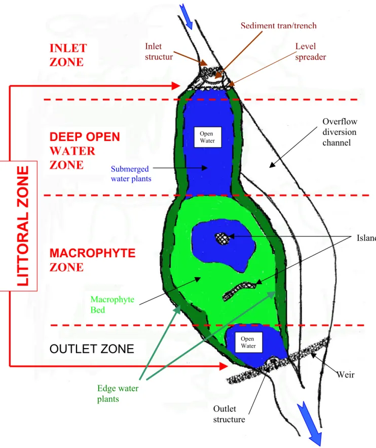
LITTORAL ZONE
DEEP OPEN WATER ZONE
MACROPHYTE ZONE
OUTLET ZONE
Macrophyte Bed
Outlet structure
Weir Island
Open Water Open
Water
Submerged water plants
INLET ZONE
Inlet structur
Sediment trap/trench Level spreader
Edge water plants
Overflow diversion channel
Figure ES1. Major Components of On-Line Constructed Wetland
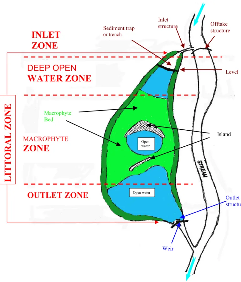
INLET ZONE
DEEP OPEN WATER ZONE
MACROPHYTE
ZONE
OUTLET ZONE
LITTORAL ZONE
Macrophyte Bed
Open water
Open water
Level Offtake structure Sediment trap
or trench
Inlet structure
Island
Weir
Outlet structure
Figure ES2. Major Components of Off-Line Constructed Wetland
Constructed Wetlands - Key Considerations
Design Criteria
• Minimum contributing drainage area of 8/10ha; 1.5/2.0ha for a pocket wetland
• Minimum dry weather flow path of 2:1
(length:width) should be provided from inflow to outflow; avoid short-circuiting
• Minimum of 40 - 50% open water with minimum of 35 - 40% surface area having a depth of 2.5cm; 10 – 15% of surface area should be a deep pool (0.5 – 2.0 m depth)
• Sediment pre-treatment (e.g sediment forebay or pre-settlement pond) of 10 – 15% total wetland cell volume
• Variable wetting-drying cycle to encourage macrophyte growth/diversity; hydraulic retention time of 12 – 24 hours for the design storm event
Advantages/Benefits
• Good nutrient, bacterial, oil and solids removal
• Can provide natural wildlife habitat and public amenity feature
• Relatively low maintenance costs Disadvantages/Limitations
• Requires fairly large land uptake
• Needs continuous baseflow (i.e. minimum water level) for viable wetland
• Sediment regulation is critical to sustain long term wetland performance
Maintenance Requirements
• Monitor and ensure initial plant establishment period
• Replace wetland vegetation to maintain at least 35 – 40% coverage
• Remove invasive vegetation
• Monitor sediment accumulation and remove periodically
STORMWATER MANAGEMENT SUITABILITY
• Extreme flood protection
• Receiving water quality
• Downstream channel protection
• Overbank flood protection
• Accepts first-flush runoff
• Requires minimum 0.75 – 2.0 m separation distance to water table IMPLEMENTATION
CONSIDERATIONS
Land requirement: M - H Capital costs: M Maintenance Burden Shallow wetland: M
Extended detention shallow wetland: M Pocket wetland: M - H
Wetland/Pond: M Residential/Commercial use
Unsuitable for high density, ultra-urban core areas
Permeable soils will require liner L= Low;M= Moderate;H= High
POLLUTANT REMOVAL 70 - 80% Total suspended solids;
bacteria 40 - 50% Nutrients 50 – 60% Heavy Metals 60 - 70% Oils, hydrocarbons
Plate 1. View of Pond F/G looking towards the outlet, with the A34 (Newbury Bypass) in the background. Retro fitted sub-surface flow wetland and balancing pond
Plate 2. Overview of Pond B looking towards the inlet, alongside the A34 (Newbury Bypass). Surface flow constructed wetland and balancing pond
Plate 3. A constructed wetland within a commercial development in Milton Keynes, providing flood storage, pollutant treatment and aesthetic amenity value
Plate 4. Vegetated balancing pond at Aztec West Business Park, near Bristol, with ecological features and aeration
1. INTRODUCTION 1.1 Background and Context
It has been widely recognised for some time that urban runoff, particularly from motorways, contains a range of pollutants that can have detrimental impacts on receiving waters, both ground and surface. The increase in road construction and especially the widening of existing motorways under the Government’s `Roads Programme’ highlighted the issue of increased volumes of highway runoff and the potential pollution of ground water and surface waters. The Environment Agency are involved in the assessment of the effects of urban runoff and mechanisms for the reduction of deleterious effects in receiving waters.
In recent years the Environment Agency has investigated available treatment methods for urban runoff, which include grass swales, detention ponds and constructed wetlands based on reedbed treatment technology. Particular emphasis has been placed on the consideration of constructed wetlands for urban runoff treatment for a number of reasons, including:
potential for high pollutant removal performance for low capital and operating costs;
capability for treating large volumes of runoff which could not realistically be treated by conventional mechanical methods; and potential for ecological and aesthetic enhancement opportunities.
Constructed wetland systems have been used extensively for the treatment of municipal, industrial and agricultural effluent. However, the treatment of urban runoff by constructed wetlands has only recently been adopted and investigated.
1.2 Aim
The aim of this Guidance Manual is to provide information on the design, construction, operation and maintenance of constructed wetlands, including the configuration, planting medium, water levels and type and extent of the vegetation in order to effectively treat urban and road runoff.
This Manual includes the following information:
Examples of the various types of Wetlands and how they work (Section 1);
guidance regarding the design and planting of a constructed wetland system and the retrofitting of existing treatment structures (Section 2);
the performance and costs of urban wetlands (Section 3);
the operation and maintenance requirements for constructed wetland systems (Section 4)
the use of wetlands to encourage wildlife and enhance the landscape (Section 5)
the implementation of Sustainable Drainage systems (SuDS), including constructed wetlands, and catchment planning (Section 6)
the use of decision support approaches for selecting SuDS systems (Section 7)
recommendations for future research (Section 8).
The user may only require information on constructed wetland design, operation and maintenance from Sections 2 and 4 with costs from Section 3. However, the Guidance Manual is designed to provide background information to wetlands (Section 1) in addition to the criteria for selecting and implementing them as a SuDS option (Sections 6 and 7). It is hoped that the guidelines for enhancing the landscape (Section 5) will be of use to both engineers and landscape architects.
1.3 Wetland Types and Definitions 1.3.1 Definitions.
Wetlands are a generic term covering a variety of water bodies supporting aquatic vegetation and providing a biofiltration capability. They include not only natural marsh and swamp environments but also artificially constructed storage basins or ponds. Wetlands are essentially transitional between terrestrial and aquatic systems, where the water table is normally at or near the soil surface or where there is a permanent shallow water cover. However, the presence of water by ponding, flooding or soil saturation is not always a good indicator of wetlands as they can often appear to be dry. Nevertheless, wetlands possess three basic characteristics:
• an area supporting (at least periodically) hydrophytic vegetation i.e. plants which grow in water
• substrates which are predominantly undrained hydric (continually wet) soils
• non-soil (rock/gravel) substrates which are either saturated with water or have a shallow, intermittent or seasonal water cover.
1.3.2 Natural and semi-natural wetlands.
Natural wetlands typically exhibit gradual hydroperiods (i.e. variation in water level), complex topographic structures, moderate to high wildlife habitat value, support few exotic species and are self-sustaining. They can be classified into three basic types:
The Welsh Harp, N W London
The Welsh Harp basin, whilst originally constructed as an ornamental reservoir, now serves as a storm runoff attenuation facility for the highly urbanised 5.2 km2 Silk Stream catchment, with some 60% of the annual flow volume being derived from impermeable surface runoff. The wet retention basin has an extensive Typha and Phragmites wetland marsh located at the inlet which has become an important wildfowl and bird reserve. Studies have shown that this semi-natural wetland functions as an effective pollution control facility for the treatment of urban runoff removing some 97% of Suspended Solids (SS) and between 50-80% of the hydrocarbons contained in both water and sediment passing through the basin. The Biological Monitoring Working Party (BMWP which assess the macroinvertebrate community status) scores improve from a very depressed value of 5 immediately upstream of the inlet to 50 below the wetland.
Fir Wood Nature Reserve, Herts
A small natural wetland located near to Junction 24 on the M25 at Potters Bar receives soil-filtered runoff from the motorway. Although aqueous metal levels recorded in the wetland are well below statutory water quality standards, metal sediment levels show moderate to high levels of contamination.
• swamps which are dominated by water-tolerant woody plants and trees
• marshes dominated by soft-stemmed emergent plants such as rushes, reeds and sedges (but which can
also contain submergent and floating plants)
• bogs which are characterised by acidic and low-nutrient water and acid-tolerant mosses.
Although natural wetlands and their surrounding riparian area reduce diffuse pollution, they do so within a definite range of operational conditions. When either hydrologic or pollutant loadings exceed their natural assimilative capacity, they rapidly become stressed and degraded.
It is also possible to recognise a separate category of semi- natural wetlands that have developed in open water situations after colonisation by aquatic vegetation. Such semi- natural, self-seeded wetlands can be found in open waters initially designed as flood storage reservoirs (retention/detention basins) or
ornamental ponds in urban areas. They also quite frequently occur in disused gravel pits, silt and ash (PFA) lagoons (Merritt, 1994). The Ruxley gravel pits adjacent to the River Cray in Kent and the Great Linford pits on the upper Ouzel in Milton Keynes are also examples of self-seeded, wetland marshes. Both are important nature reserves and community assets and also have significant functions as stormwater balancing facilities.
1.3.3 Artificial or created wetlands.
Artificially constructed wetland storage basins or ponds which create "generic"
wetland habitats, have the more limited objectives of flood and pollution control.
Created stormwater wetlands which are dependent on surface water runoff are "semi- tidal" in nature, being continuously exposed to episodic inundation and subsequent drawdown. The extent of the changes in water level impose quite severe physiological constraints on the plant community. The resulting created wetland systems typically have a more clearly defined open water component than natural wetlands. The types of artificial constructed wetlands which can function as urban stormwater facilities include:
Rye House Nature Reserve
The 5 ha Rye House nature reserve in the lower floodplain of the River Lea and operated jointly by the RSPB and Thames Water, is an example of a long established constructed shallow marsh.
The wetland marsh was created in 1973 taking 90 Ml/day of treated sewage effluent from the adjacent tertiary treatment lagoons of Rye Mead sewage works. The wetland marsh is now managed as a series of compartments demonstrating a range of habitats from shallow pools and scrapes, through reed bed to carr.
The Ouzel Valley Lakes
The series of wet retention (balancing) lakes located in the Ouzel valley at Milton Keynes contain marginal aquatic vegetation which is partly semi-natural and partly artificially introduced. The largest lakes in this balancing system are Mount Farm Lake (95ha), Willen Lake (87ha) and Caldecotte Lake (44ha). All three are fringed by both emergent and submergent macrophytes which not only provide enhanced ecological and amenity functions, but also help to reduce the elevated nutrient, oil and heavy metal concentrations associated with wet weather urban surface discharges.
Extended Detention Basins in Essex and Herts
The 65ha Pinnacles Industrial Estate at Harlow, Essex discharging surface water to a 19,400 m3 capacity storage basin and 10.93 ha of the M11 at Stansted Brook in Hertfordshire which discharges to a 4,900 m3 capacity dry basin, now have low-level marsh located in the base of the storage facilities.
Shallow marsh systems requiring considerable space and which drain contributing areas often in excess of 10 hectares.
They demand a reliable baseflow or groundwater supply to support emergent wetland plants. The 140 ha Potteric Carr Reserve at West Bessacarr near Doncaster receives surface runoff from a 1261 ha mixed urban catchment, is a very
large marsh system. Whilst being a designated nature reserve dominated by carr marsh, it also retains its function as a major flood storage facility. The "water meadows" in the Chells district of Stevenage similarly operate as shallow marshes fed by overbank flows from the Aston End Brook generated by urban surface runoff during storm events.
Retention or wet (balancing) ponds/basins having a permanent water volume are amongst the most frequently
encountered flood storage facilities in the UK for managing and controlling urban and highway runoff.
Surface stormwater runoff displaces the water lying in the basin at the commencement of
the storm event. Sedimentation within the basin will occur as well as biological uptake and other forms of treatment (volatilisation, complexation, photo-oxidation etc.). Retention ponds can have marginal rooted and submergent/floating aquatic vegetation with open water comprising typically some 50 - 75% of the total basin surface area.
Small, semi-permanent (low-lying) marshes and pools have been frequently incorporated into dry detention
basins to form an extended detention (ED) basin. Such wetlands (of between 10-25% of the total basin area) facilitate pollutant removal and mitigate
against short-circuiting, channelisation and sediment re-entrainement. A few ED basins are now being formally introduced under the SEPA SUDS initiative in Scotland on the Dunfermline (Eastern Expansion, DEX) site in Fife. There is a modified ED basin with a semi-permanent pool as well as a low level wetland marsh in the off-line 38,000 m3 detention basin located at North Weald, Essex and a number of industrial/commercial estates have extended dry detention basins to incorporate a wet marsh facility. A number of originally dry detention basins have shallow marsh/wetland vegetation occupying some part of the basin floor and now effectively function as extended detention facilities with the vegetation filtering out pollutants contained in the influent surface water flows.
The A34 Newbury Bypass
A total of nine flood storage basins have been built alongside the A34 Newbury Bypass to control and treat surface water design discharges varying between 20-120 l/s, from 13.5 km of dual, two-lane trunk road. Maximum design storage volumes vary between 121-676 m3 with retention times of between 30-120 hours. One storage basin has been retrofitted with a SSF constructed wetland (Phragmites) and wet weather removal rates recorded for the wetland system has been high with SS and heavy metal removal efficiencies varying between 40-75% and 59-98% respectively.
District Park (DEX), Dunfermline, Fife, Scotland
Combined dry/wet retention basins and SF wetlands treat surface water from a 600ha light industrial/commercial and highway catchment. Percentage metal removals from the wetlands are Cu 33%, Pb 25% and Zn 65%. Mean metal sediment levels are Cu 13, Pb 10.5 and Zn 30.2 mg/kg .
Combined pond/wetland (retention/detention) basins are storage facilities where part of the containing basin is given over to dead storage (permanent pools) and part to live (fill and drain) storage. Such combined retention/detention wetland designs have been adopted for the control and
management of highway runoff as on the A34 Newbury bypass, the A4/A46 Bathford roundabout and at the M49 junction to the east of the southern Severn Bridge crossing. The designs frequently possess a front-end pool or chamber which traps sediment and
associated pollutants providing treatment for the first flush and (the more frequent) small runoff events. The wetland cell (which can be separated by a filter strip or gabion wall from the permanent pond), provides for temporary storage, secondary biological treatment and attenuation of runoff from larger more infrequent storms. A final micropool or settlement pond might also be included to give a more limited tertiary treatment.
1.4 Constructed Wetlands and Flow Systems 1.4.1 Constructed wetlands
Constructed wetland basins normally have non-soil substrates and a permanent (but normally shallow) water volume that can be almost entirely covered in aquatic vegetation. Constructed wetlands may contain marsh, swamp and pond (lagoon) elements; the inlet zone for example,
can resemble the latter form and be used as a sediment trap. The dominant feature of the system is the macrophyte zone containing emergent and/or floating vegetation that requires (or can withstand) wetting and drying cycles.
Constructed wetlands lack the full range of aquatic functions exhibited by natural wetlands and are not intended to provide species diversity. Whilst natural
wetlands depend upon groundwater levels,
constructed stormwater wetlands are dominated by surface runoff in a random “semi- tidal” hydroperiod characterised by cyclic patterns of inundation and drawdown.
Such constructed wetlands typically experience much greater sediment inputs than natural wetlands. In addition to a more restricted aquatic flora, they are likely to provide an environment favourable to invasive terrestrial weed species especially during plant establishment. Open water would normally occupy up to 25 - 30% of the total basin surface area with remaining areas comprising shallows up to a maximum
Anton Crescent, Sutton, Surrey
The 1.3 ha Anton Crescent wetland in Sutton, Surrey has been built in a wet detention basin which serves a mixed residential and light commercial catchment. The basin has a maximum design storage capacity of 10,000 m3 with a mean retention time of 10.8 days. The SF constructed wetland was planted with Typha to provide a wildlife conservation area and a local amenity/educational facility and now also provides a valuable water quality function with average removal rates for SS, Zn and Faecal Coliforms of 56%, 37% and 78%
respectively .High metal levels are associated with the sediments filtered out by the macrophyte roots and stems (Cu 40, Pb 126.6 and Zn 120.7 mg/kg.
Keytec 7 Pond, Pershore, Worcs.
The 10.9ha Keytec Industrial estate pond in Pershore, Worcs was designed as a flow balancing facility with a SF constructed wetland to provide 1500m3 of stormwater storage with a retention time of 15-20 hours. The imposed pollution discharge consents for SS (100mg/l), BOD (20mg/l) and oils/hydrocarbons (5mg/l) have been successfully met throughout the operational lifetime of the basin.
depth of 0.5m. Flood storage can also be added above the treatment wetland where the surrounding terrain permits
1.4.2 Constructed wetland flow systems
Although the design of artificially constructed wetlands varies making each system unique, the basic flow configurations can be divided into two categories:
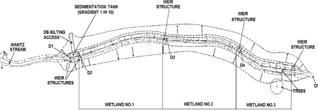
Surface flow (SF) or free water surface (FWS) systems which are similar to natural marshes in that they are basins planted with emergent, submergent and/or floating wetland macrophyte plants. Such free surface water treatment wetlands mimic the hydrologic regime of natural wetlands. Almost all constructed wetlands in the UK for the treatment of urban runoff comprise surface flow systems and resemble natural marshes, in that they can provide wildlife habitat and aesthetic benefits as well as water treatment. The influent passes as free-surface (overland) flow (and/or at shallow depths) and at low velocities above the supporting substrates. Figure 1.1a and b shows a (3 x 80m) linear SF design which has been retrofitted into a widened stream channel in Dagenham, East London to treat surface runoff from a 440ha residential and commercial area. The 1750m2 modular wetland system is designed to meet 50% removal efficiencies for targeted pollutants (BOD, Pb, Zn, and SS).
SF/FWS systems with low flow rates are susceptible to winter ice-cover in temperate climates such as the UK, and have reduced efficiencies during such times since effective water depth and retention time are reduced .
Figure 1.1a. SF Constructed Wetland Design (R Wantz, Dagenham, E London.)
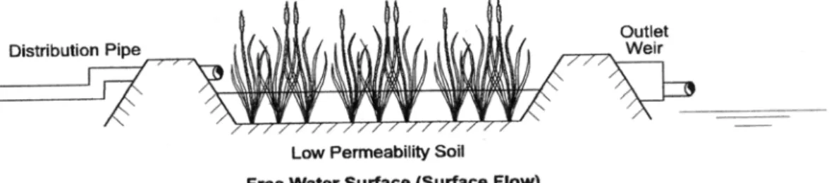
Figure 1.1b. SF Constructed Wetland Illustrative Cross-section (After: Kadlec and Knight, 1996)
Subsurface flow (SSF) systems operate with the influent flowing below the surface of the soil or gravel substrate. Purification occurs during contact with the plant roots and substrate surfaces, which are water-saturated and can therefore be considered to be oxygen-limited. The substrate in these systems is thermally insulated by the overlying vegetation and litter layer and so the wetland performance is not significantly reduced during the winter. Most of the earliest wetland treatment systems in Europe were SSF systems constructed to treat domestic wastewater. There are two basic flow configurations for SSF wetlands:
- horizontal flow (HF) systems where the effluent is fed in at the inlet but then flows slowly through the porous medium (normally gravel) under the surface of the bed in a more or less horizontal path to the outlet zone. These HF systems are also known in the UK as Reedbed Treatment Systems (RBTS) as the most frequently used plant is the common reed (Phragmites australis).
- vertical flow (VF) systems, which usually have a sand cap overlying the graded gravel/rock substrate, and are intermittently dosed from above to flood the surface of the bed. The effluent then drains vertically down through the bed to be collected at the base. Such VF systems are similar in design and operation to conventional percolating filters but are very rarely found on surface water drainage systems (Table 1.1).
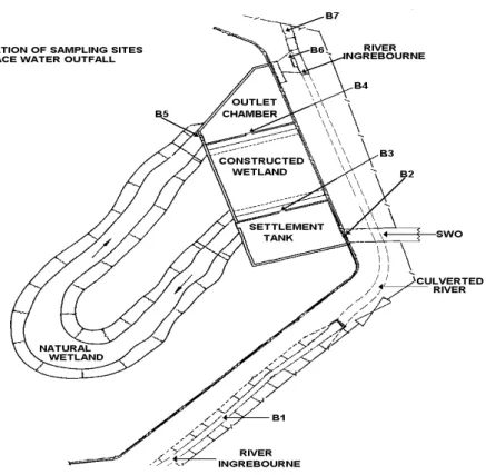
Figure 1.2a and b illustrates a SSF constructed wetland system located at Brentwood, Essex to treat surface water discharges from a 400ha mixed urban catchment prior to entry into the River Ingrebourne. During high flows, untreated effluent also overflows into a natural Typha wetland in addition to passing through the SSF Phragmites wetland before final discharge to the river. The total wetland area is 204m2 and the mean retention time is 50 minutes. Dry weather removals average 30 - 33% for Pb and Cu, 19% for Zn, 18% for SS, 26% for BOD and 50% for total ammonia with mean metal sediment removals varying between 17 - 33% .
Welford Mini-Wetland, Leics
A pocket or mini-wetland can be found on the outskirts of the S Leicestershire village of Welford where surface water from the A50 has been drained to support a linear 0.25 ha marsh site immediately adjacent to the highway and which helps to alleviate flooding on a dip in the carriageway. The development was entirely the result of local community effort with technical advice from the Groundwork Trust and provides an aesthetic environmental focus for the village.
Figure 1.2a. A SSF Constructed Wetland (Brentwood, Essex)
Figure 1.2b. A SSF Constructed Wetland Illustrative Cross-section (After: Kadlec and Knight, 1996)
1.5 Pocket or Mini-Wetlands
A particular form of compact (or pocket) stormwater constructed wetland which has been developed in the eastern United States and which is suitable for small sites of 0.5 - 5.0 hectares. Such pocket wetlands may not have a reliable source of baseflow and thus are subject to large fluctuations in water level.
Wharrage Brook, Redditch, Worcs.
The Environment Agency Midlands Region has constructed a modular treatment train system downstream of the urbanised section on the Wharrage Brook near Redditch, Worcs. A primary silt trap is followed by wet retention for flow and quality balancing and a final SF reedbed for stabilisation and treatment. The retrofitted design provides a maximum storage capacity of 3500 m3 and serves a 4km2 mixed urban catchment. Extensive surrounding landscaping has also provided valuable wildlife habitats and amenity features for the local urban community.
Webheath, Redditch, Worcs.
A 4 cell modular wetland system preceded by a small sedimentation basin has been recently retrofitted into a 270 housing development site at Webheath, Redditch. The linear reed bed cells (25m x 5m) have been retrofitted into a narrow pre-existing degraded channel on the site and provide a void storage of 50 m3 per impervious hectare for the initial 5mm of effective rainfall-runoff.
1.6 Modular or Treatment-Train Systems
The various types of storage basin all have similar basic design principles. They can be used in-series or as modular cells
within a single overall structure and can be adapted to either on or off-line configurations. The module sequencing is important in order to ensure that the primary function of each is sustainable. One effective form of treatment-train might consist of an inlet sediment trap or forebay, followed by a wet retention or dry
detention basin which is then discharged to a full wetland system. Islands in open water zones also provide important habitat and landscaping elements.
Series (or treatment-train) configurations can help to improve the treatment performance and can be particularly useful on steep sites, sites having several small separate "vacant" areas or in
narrow, linear spaces along fields, road edges or river corridors. They can also be used as a basis for retrofitting SuDS components into cramped
existing urban developments as evidenced by the restoration scheme in the floodplain of the River Skerne in Darlington . A linear series of small wetlands have also been successfully retrofitted into a ditch carrying the discharges from filter drains on the southern carriageways of the M25 just south of Junction 15 near Heathrow Airport.
1.7 How Wetlands Work 1.7.1 Introduction
A wetland system consists of biotic (plant, algae and associated fungi and bacteria) and abiotic (surface and interstitial water, sediment and detrital material) compartments. Each of the compartments can serve to differing degrees, as a storage location for pollutants entering the wetland. The vascular plants transfer nutrients, gas and other materials (including pollutants) from one part of the plant to another.
The microbial compartment is extremely complex and is probably the least understood although it may be the most important wetland component. The micro- organisms are found in the water column, attached to living and dead organic material and within the detritus that builds up on the wetland substrate. Some (facultative) bacteria can grow in either aerobic or anaerobic environments whilst others (obligate bacteria) are specific to either aerobic or anaerobic conditions. Bacteria have a direct role in nutrient cycling and through their oxygen consumption can contribute to an increase in wetland BOD levels. Certain organic and inorganic material can accumulate in the wetland substrate and lead to predominantly oxygen-deficient sediments which generally tend to inhibit decomposition and oxidation reactions.
This means that associated metals, oils and nutrients can be tied-up in the sediment for long periods.
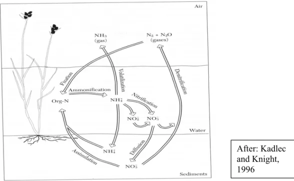
When pollutants enter the wetland they are acted upon by biological, chemical and physical processes which interact in a complex fashion. Figure 1.3 illustrates in a simplified form the interactions which occur in a wetland system between the air- water-sediment phases during sequential nitrogen transformations. Plants will take up dissolved inorganic nutrients (ammonia, nitrate, phosphate etc.) and incorporate them into their tissue whilst bacteria and fungi attack the organic material, utilising both carbon compounds and nutrients. The wetland biota die and become detritus in the
Figure 1.3. Nitrogen Transformation in a Wetland System
basal sediments or may be washed downstream. On an annual basis, pollutants may become buried in the sediments, transformed from one form to another, lost to the atmosphere or washed out of the wetland system either in the original or an altered form.
1.7.2 Pollutant removal processes
In order that the design and operational characteristics of wetland treatment systems are satisfactorily specified, it is necessary to have an understanding of the basic pollution removal mechanisms. Pollutants in urban surface runoff can be removed by wetlands as a result of sediment attachment, degradation, transformation and transfer.
They can also be transferred to the atmosphere or groundwater although the latter pathway should be prevented by the use of an impermeable base or liner. The principal physical, chemical and biological removal mechanisms include sedimentation, adsorption, precipitation and dissolution, filtration, bacterial and biochemical interactions, volatilisation and infiltration. Further details on these specific processes are given in Appendix A. Due to the complex interactions between the physical and biochemical processes which occur in wetland systems, these
After: Kadlec and Knight, 1996
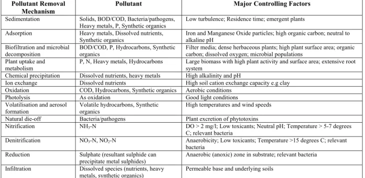
Table 1.1a. Wetland Pollutant Removal Mechanisms and their Major Controlling Factors
Pollutant Removal Mechanism
Pollutant Major Controlling Factors
Sedimentation Solids, BOD/COD, Bacteria/pathogens, Heavy metals, P, Synthetic organics
Low turbulence; Residence time; emergent plants Adsorption Heavy metals, Dissolved nutrients,
Synthetic organics
Iron and Manganese Oxide particles; high organic carbon; neutral to alkaline pH
Biofiltration and microbial
decomposition BOD/COD, P, Hydrocarbons, Synthetic
organics Filter media; dense herbaceous plants; high plant surface area; organic carbon; dissolved oxygen; microbial populations
Plant uptake and metabolism
P, N, Heavy metals, Hydrocarbons Large biomass with high plant activity and surface area; extensive root system
Chemical precipitation Dissolved nutrients, heavy metals High alkalinity and pH
Ion exchange Dissolved nutrients High soil cation exchange capacity e.g clay Oxidation COD, Hydrocarbons, Synthetic organics Aerobic conditions
Photolysis As oxidation Good light conditions
Volatilisation and aerosol formation
Volatile hydrocarbons, Synthetic organics
High temperatures and wind speeds Natural die-off Bacteria/pathogens Plant excretion of phytotoxins
Nitrification NH3-N DO > 2 mg/l; Low toxicants; Neutral pH; Temperature > 5-7 degrees C; relevant bacteria
Denitrification NO3-N, NO2-N Anaerobicity; Low toxicants; Temperature >15 degrees C; relevant bacteria
Reduction Sulphate (resultant sulphide can precipitate metal sulphides)
Anaerobic (anoxic) zone in substrate; relevant bacteria Infiltration Dissolved species (nutrients, heavy
metals, synthetic organics)
Permeable base and underlying soils
Table 1.1b. Relative Importance of Wetland Pollutant Removal Mechanisms
Pollutant Pollutant Removal
Mechanism Settleable solids
Colloidal solids
BOD N P Heavy
metals
Organics Bacteria, pathogens
Description
Physical Sedimentation Filtration Adsorption
P S
S S S
I I I
I I I S
I
S
I I
Gravitational settling of solids (and adsorbed pollutants).
Particulate filtered mechanically as water passes through substrate and/or root mass.
Inter-particle attractive forces Chemical
Precipitation Adsorption Decomposition
P P P
S
S I
P P
Formation of co-precipitation with insoluble compounds.
Adsorption on substrate and plant surfaces.
Decomposition or alteration of less stable compounds by UV irradiation, oxidation, reduction etc
Biological
Bacterial metabolisma
Plant metabolisma
Plant uptake Natural die-off
P P P
S
S I
S
S I
S
P
S
S
S
P
Removal of colloidal solids and soluble organics by suspended benthic and plant supported bacteria. Bacterial nitrification and denitrification.
Metabolism of organics and other pollutants by plants. Root excretions may be toxic to certain micro-organisms.
Significant quantities of these pollutants will be taken up by the roots.
Natural decay of organisms in an unfavourable environment
KEY: P = Primary effect; S = Secondary effect
I = Incremental effect (an effect occurring incidental to removal of another pollutant)
a The term metabolism includes both biosynthesis and catabolic reactions
Hydraulic Retention Time (HRT)
The nominal HRT (days) is the volume (LWD) of free water in the wetland divided by the volumetric inflow rate (Qin; m3/day):
HRT = LWD/Qin (or D/Qin )
Where L and W are length and width (m); D is free water depth (expressed as: porosity x water depth). Mean retention time can also be determined by undertaking an accurate tracer study.
Porosity (Void Fraction)
Porosity (expressed as a decimal fraction) = Total Void Volume (m3) / Total Wetland Volume (m3) In an SSF wetland, free water volume fractions are
removal mechanisms are not independent. The considerable variation in wetland characteristics e.g hydrology, biota, substrates etc., means that the dominant removal mechanisms will vary from one wetland to another as well as between differing storm events affecting the same wetland system. These inter- and intra-wetland variations help to explain why wetland pollutant removal efficiencies can vary with respect to both temporal and spatial resolution. Tables 1.1a and b summarise the principal mechanisms that capture, retain and transform various pollutant species found in urban runoff and the controlling factors that promote the various removal mechanisms and which lead to improved water quality.
As noted previously, the large majority of UK urban wetlands are free water surface systems containing emergent macrophytes in which the near-surface water layer is aerobic but with the deeper water and substrate being normally anaerobic. A constructed wetland has been traditionally thought to provide a combined aerobic- anaerobic environment. The anaerobic zone surrounds the root zone and at the same time provides a mini-aerobic zone surrounding the root hairs formed by the oxygen passed down from the stems and/or leaves of the aquatic vegetation and contributing to the degradation of oxygen-consuming substances and to nitrification. Ammonia is also oxidised into nitrate by nitrifying bacteria in aerobic zones (see Figure 1.3) with denitrification converting nitrate to free nitrogen (or nitrous oxide) in the anaerobic bottom layers and substrate by denitrifying bacteria. These processes will occur most rapidly during summer periods when high temperatures stimulate microbial activity.
Solids, settleable organics and solid-associated pollutants such as bacteria, metals and oils are very effectively removed by the physical filtration offered by the vegetation which imposes a considerable hydraulic resistance to the incoming flow.
Soluble metals are typically transformed by microbial oxidation and precipitated in the wetland substrate in the form of oxides or sulphates with soluble BOD removed by both attached and suspended microbial growth in the aerobic surface water layers.
1.7.3 Hydraulic retention time and loading rates
Perhaps the most important factor influencing the treatment mechanism function is hydraulic retention time i.e the average
time that stormwater remains in the wetland. This can be expressed as the ratio of the mean wetland volume to mean outflow (or inflow) rate although it must be noted that if short- circuiting (or high summer evapotranspiration) occurs in the
wetland, then the effective retention time can significantly differ from the calculated retention time. In addition, it incorrectly assumes that the entire wetland water volume is involved in the flow and that detention time response to variation in influent flow and pollutant
characteristics is linear. Wetlands should have a minimum retention time of at least 10 - 15 hours for the design
Hydraulic Loading Rate (HLR)
HLR (m/d) is equal to the inflow rate (Qin; m3/d) divided by the wetland surface area (As; m2 ):
HLR = Qi / As
It does not imply that the inflow is uniformly distributed over the wetland surface.
average annual storm volume for a minimum of 5 - 10 hours to achieve a high level of removal efficiency. When calculating the retention time for a SSF wetland system, the volume of the bed media must also be considered. The retention time of the bed is calculated from the porosity (or void fraction) of the substrate, which represents the fraction of the wetted volume that is occupied by free (drainable) water. The higher the porosity, the greater the retention volume of water per unit volume of media.
However, excessive porosity can lead to scour in the bed causing breakdown of the substrate.
The effectiveness of solids settling is directly related to the particle sedimentation time and time is also a crucial variable determining the efficiency of the biochemical processes. Chemically and biologically-mediated processes both
have characteristic reaction rates that must be satisfied if optimum treatment is to be achieved. Thus hydraulic loading rates, water depths and duration of flooding become important criteria for the operation of wetland systems and these need to be considered on a site-specific basis in terms of design storm, substrate and vegetation conditions. It has been suggested that a hydraulic loading rate of 0.2 m3/m2/day provides for maximum treatment efficiency whilst another study has recommended guidelines of up to 1m3/m2/day (wetland surface area) and a void storage capacity of 50m3 and 100m3 per impervious hectare respectively for 5mm and 10mm effective runoff volume. These latter hydraulic design parameters have been successfully used in the modular wetland systems developed by the Environment Agency for urban runoff control and treatment within the Lower Severn area.
1.8 Wetland classification
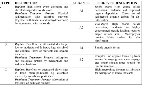
Research and field surveys have identified a number of quite different pollutant pathways, transformations and interception processes in urban wetlands. These processes operate as an inter-active function of inflow conditions (hydrology, hydraulics etc.) and pollutant characteristics (solids and toxic concentrations, organic loads etc.). Based on a consideration of the controlling processes, it is possible to theoretically identify three fundamental types of constructed wetland (Table 1.2).
Type A is essentially configured as a primary settling facility to maximise sedimentation and where solids capture is the operational objective. Type A can be of single or two-stage form with the latter configuration intended to utilise the sediment adsorptive capacity to lock-in and degrade nutrients. Type B is intended to provide a secondary biological treatment for surface runoff that may be low in solids but carrying high levels of organics and soluble pollutants. Type C provides a hybrid tertiary form of treatment for low flow volumes that may be associated with concentrated levels of micro-pollutants such as dissolved metals or pesticides. With the predominantly temperate climatic conditions and variety of soil types encountered in the UK, most urban wetlands will be of Type A and B1 and most frequently comprise a combined hybrid of these two types constructed in an on-line mode.
Table 1.2. A Process-based Classification of Constructed Wetlands
TYPE DESCRIPTION SUB-TYPE SUB-TYPE DESCRIPTION
A1
Single stage: High coarse solids deposition; moderate and dispersed organic deposition. Direct use of sedimented organic carbon for de- nitrification
A Regime: High storm event discharge and elevated suspended solids levels
Dominant Treatment Process: Physical sedimentation with adsorbed nutrients (together with bacteria and oil/hydrocarbons) being removed with the solids.
A2
Two-stage: High coarse solids deposition; moderate to highly concentrated organic loading; requires larger surface area. Macrophytes provide labile carbon for de- nitrification
B1 Simple organic forms B Regime: Baseflow or attenuated discharge,
low to moderate solids input; high dissolved and colloidal forms of nutrients and organic materials.
Dominant Treatment Process: adsorption and biological uptake by macrophyte and sediment biofilms
B2
Complex fine organic forms e.g from swamp drainage, groundwater seepage etc; longer contact times needed for biofilm removal.
C Regime: Baseflow or attenuated flows high in toxic micro-pollutants e.g dissolved metals, hydrocarbons, pesticides.
Dominant Treatment Process: adsorption of toxicants on cellulose biomass
High macrophyte biomass as substrate for adsorption of micro-toxicants
2. WETLAND DESIGN 2.1 Introduction
Factors that will determine the selection of the most appropriate design criteria include:
local climate, topography and geology;
traffic loadings (present and future);
road drainage area;
land availability;
cost;
size/extent and type of receiving water body;
water quality classification and objective (including water uses); and
environmental enhancement value.
A constructed wetland system to treat highway runoff should ideally include the following structures:
oil separator and silt trap;
spillage containment;
settlement pond and associated control structures;
constructed wetland and associated control structures;
final settlement tank;
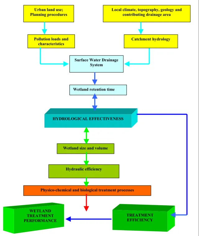
outfall into receiving watercourse; and access.
The successful design of constructed wetlands for urban surface runoff management requires the adoption of an integrated multi-disciplinary approach as performance criteria are difficult to set given the inherent random fluctuations in discharge and pollution loadings which characterise stormwater runoff. This temporal and spatial variability makes it difficult to define retention time and hydraulic loading and thus general design rules for urban stormwater wetlands have been developed from empirical performance data and using "single-number" techniques such as drainage