E
NERGY AND
E
NVIRONMENT
Volume 3, Issue 4, 2012 pp.505-520
Journal homepage: www.IJEE.IEEFoundation.org
Exergoeconomic performance optimization of an
endoreversible intercooled regenerative Brayton combined
heat and power plant coupled to variable-temperature heat
reservoirs
Bo Yang, Lingen Chen, Fengrui Sun
College of Naval Architecture and Power, Naval University of Engineering, Wuhan 430033, P. R. China.
Abstract
An endoreversible intercooled regenerative Brayton combined heat and power (CHP) plant model coupled to variable-temperature heat reservoirs is established. The exergoeconomic performance of the CHP plant is investigated using finite time thermodynamics. The analytical formulae about dimensionless profit rate and exergy efficiency of the CHP plant with the heat resistance losses in the hot-, cold- and consumer-side heat exchangers, the intercooler and the regenerator are deduced. By taking the maximum profit rate as the objective, the heat conductance allocation among the five heat exchangers and the choice of intercooling pressure ratio are optimized by numerical examples, the characteristic of the optimal dimensionless profit rate versus corresponding exergy efficiency is investigated. When the optimization is performed further with respect to the total pressure ratio, a double-maximum profit rate is obtained. The effects of the design parameters on the double-maximum dimensionless profit rate and corresponding exergy efficiency, optimal total pressure ratio and optimal intercooling pressure ratio are analyzed in detail, and it is found that there exist an optimal consumer-side temperature and an optimal thermal capacitance rate matching between the working fluid and the heat reservoir, respectively, corresponding to a thrice-maximum dimensionless profit rate.
Copyright © 2012 International Energy and Environment Foundation - All rights reserved.
Keywords: Finite time thermodynamics; Intercooled regenerative Brayton combined heat and power plant; Exergoeconomic performance; Profit rate; Optimization.
1. Introduction
reheat and total pressure ratio on the performance of the CHP plant. Khaliq and Choudhary [5] evaluated the performance of intercooled reheat regenerative gas turbine CHP plant by using the first law (energetic efficiency) and second law (exergetic efficiency) of thermodynamics and investigated the effects of overall pressure ratio, cycle temperature ratio, pressure losses on the performance of the CHP plant.
Finite-time thermodynamics (FTT) [6-18] is a powerful tool for analyzing and optimizing performance of various thermodynamic cycles and devices. Some authors have performed the performance analysis and optimization for various CHP plants by using finite-time thermodynamics. Bojic [19] investigated the annual worth of an endoreversible Carnot cycle CHP plant with the sole irreversibility of heat resistance. Sahin et al [20] performed exergy output rate optimization for an endoreversible Carnot cycle CHP plant and found that the lower the consumer-side temperature, the better the performance. Erdil et al [21] optimized the exergetic output rate and exergetic efficiency of an irreversible combined Carnot cycle CHP plant under various design and operating conditions and found that the optimal performance stayed approximately constant with consumer-side temperature. Atmaca et al [22] performed the exergetic output rate, energy utilization factor (EUF), artificial thermal efficiency and exergetic efficiency optimization of an irreversible Carnot cycle CHP plant. Ust et al [23] provided a new exergetic performance criterion, exergy density, which includes the consideration of the system sizes, and investigated the general and optimal performances of an irreversible Carnot cycle CHP plant.
In industry, Brayton cycle is widely used. some authors are interested in the CHP plants composed of various Brayton cycles. Yilmaz [24] optimized the exergy output rate and exergetic efficiency of an endoreversible simple gas turbine closed-cycle CHP plant, investigated the effects of parameters on exergetic performance and found that the lower the consumer-side temperature, the better the performance. Haoand Zhang [25, 26] optimized the total useful-energy rate (including power output and useful heat rate output) and the exergetic output rate of an endoreversible Joule-Brayton CHP cycle by optimizing the pressure ratio and analyzed the effects of design parameters on the optimal performances. Ust et al [27, 28] proposed a new objective function called the exergetic performance coefficient (EPC), optimized an irreversible regenerative gas turbine closed-cycle CHP plant with heat resistance and internal irreversibility [27] and an irreversible Dual cycle CHP plant with heat resistance, heat leakage and internal irreversibility [28], and compared the results with those obtained using the total exergy output as the objective.
Exergoeconomic (or thermoeconomic) analysis and optimization [29, 30] is a relatively new method that combines exergy with conventional concepts from long-run engineering economic optimization to evaluate and optimize the design and performance of energy systems. Salamon and Nitzan [31] combined the endoreversible model with exergoeconomic analysis for endoreversible Carnot heat engine with the only loss of heat resistance. It was termed as finite time exergoeconomic analysis [32-38] to distinguish it from the endoreversible analysis with pure thermodynamic objectives and the exergoeconomic analysis with long-run economic optimization. Furthermore, such a method has been extended to universal endoreversible heat engine [39] and generalized irreversible Carnot heat engine [40] and refrigerator [41]. On the basis of Refs. [32-41], Tao et al [42, 43] performed the finite time exergoeconomic performance analysis and optimization for endoreversible simple [42] and regenerative [43] gas turbine closed-cycle CHP plant coupled to constant temperature heat reservoirs by optimizing the heat conductance allocation among the hot-, cold- and consumer-side heat exchangers, the regenerator and the pressure ratio of the compressor. Chen et al [44] and Yang et al [45] analyzed and optimized the finite time exergoeconomic performance of an endoreversible intercooled regenerative Brayton CHP plant coupled to constant-temperature heat reservoirs.
2. Cycle model
A T-s diagram of CHP plant composed of an endoreversible intercooled regenerative Brayton closed-cycle coupled to variable-temperature heat reservoirs is shown in Figure 1. Process 1-2 and 3-4 are isentropic adiabatic compression processes in the low- and high-pressure compressors, while the process 5-6 is isentropic adiabatic expansion process in the turbine. Process 2-3 is an isobaric intercooling process in the intercooler. Process 4-7 is an isobaric absorbed heat process and process 6-8 is an isobaric evolved heat process in the regenerator. Process 7-5 is an isobaric absorbed heat process in the hot-side heat exchanger and process 9-1 is an isobaric evolved heat process in the cold-side heat exchanger. Process 8-9 is an isobaric evolved heat process in the customer-side heat exchanger.
Assuming that the working fluid used in the cycle is an ideal gas with constant thermal capacity rate (mass flow rate and specific heat product) Cwf. The hot-side heat reservoir is considered to have a
thermal capacity rate CH and the inlet and the outlet temperatures of the heating fluid are THin and THout,
respectively. The cold-side heat reservoir is considered to have a thermal capacity rate CL and the inlet
and the outlet temperatures of the cooling fluid are TLin and TLout, respectively. The cooling fluid in the
intercooler is considered to have a thermal capacity rate CI and the inlet and the outlet temperatures of
the cooling fluid are TIin and TIout, respectively. The consumer-side temperature is TK. The heat
exchangers between the working fluid and the heat reservoir, the regenerator and the intercooler are counter-flow and the heat conductances (heat transfer surface area and heat transfer coefficient product) of the hot-, cold- and consumer-side heat exchangers, the intercooler and the regenerator are UH , UL,
K
U , UI, UR respectively. According to the heat transfer processes, the properties of the heat reservoirs
and working fluid, and the theory of heat exchangers, the rate (QH) of heat transfer from heat source to
the working fluid, the rate (QL) of heat transfer from the working fluid to the heat sink, the rate (QK) of heat transfer from the working fluid to the heat consuming device, the rate (QI) of heat exchanged in the intercooler, and the rate (QR) of heat regenerated in the regenerator are, respectively, given by:
[
5 7]
5 7 min 1 75 7
( ) ( )
( ) ( ) ( )
ln ( ) ( )
Hin Hout
H H H Hin Hout wf H H Hin
Hin Hout
T T T T
Q U C T T C T T C E T T
T T T T
− − −
= = − = − = −
− − (1)
[
9 1]
9 1 min 1 99 1
( ) ( )
( ) ( ) ( )
ln ( ) ( )
Lout Lin
L L L Lout Lin wf L L Lin
Lout Lin
T T T T
Q U C T T C T T C E T T
T T T T
− − −
= = − = − = −
− − (2)
8 9
8 9 8
8 9
( ) ( )
ln[( ) ( )]
K K wf wf K K
K K
T T
Q U C T T C E T T
T T T T
−
= = − = −
− − (3)
[
2 3]
2 3 Im 1 22 3
( ) ( )
( ) ( ) ( )
ln ( ) ( )
Iout Iin
I I I Iout Iin wf in I Iin
Iout Iin
T T T T
Q U C T T C T T C E T T
T T T T
− − −
= = − = − = −
− − (4)
7 4 6 8 6 4
( ) ( ) ( )
R wf wf wf R
Q =C T −T =C T −T =C E T −T (5)
where EH1, EL1, EK, EI1 and ER are the effectivenesses of the hot-, cold-, consumer-side heat
exchangers, the intercooler and the regenerator, respectively, and are defined as:
[
]
[
]
1 min max
1
min max 1 min max
1 exp (1 )
1 ( ) exp (1 )
H H H
H
H H H H H
N C C
E
C C N C C
− − −
=
− − − (6)
[
]
[
]
1 min max
1
min max 1 min max
1 exp (1 )
1 ( ) exp (1 )
L L L
L
L L L L L
N C C
E
C C N C C
− − −
=
− − − (7)
1 exp( )
K K
[
]
[
]
1 Im Im
1
Im Im 1 Im Im
1 exp (1 )
1 ( ) exp (1 )
I in ax
I
in ax I in ax
N C C
E
C C N C C
− − −
=
− − − (9)
( 1)
R R R
E =N N + (10)
where CHmin and CHmax are the smaller and the larger of the two capacitance rates CH and Cwf, CLmin and
max L
C are the smaller and the larger of the two capacitance rates CL and Cwf, CImin and CImax are the
smaller and the larger of the two capacitance rates CI and Cwf. NH1, NL1, NK, NI1 and NR are the numbers of heat transfer units of the hot-side, cold-side, consumer-side heat exchangers, the intercooler and the regenerator, respectively, and are defined as:
1 min 1 min 1 Im
min max min
max Im Im
, , , ,
min{ , }, max{ , }, min{ , }
max{ , }, min{ , }, max{ , }
H H H L L L K K wf I I in R R wf
H H wf H H wf L L wf
L L wf in I wf ax I wf
N U C N U C N U C N U C N U C
C C C C C C C C C
C C C C C C C C C
= = = = =
= = =
= = =
(11)
Defining the working fluid isentropic temperature ratios x and y for the low-pressure compressor and the total compression process, i.e. x=T T2 1 and y=T T5 6 . According to the properties of endoreversible
process, one has:
( 1) ( 1) 1
1 , , 4 3
k k k k
x=π − y=π − T =T yx− (12)
where π1 is the intercooling pressure ratio which satisfies π ≥1 1, π is the total pressure ratio which satisfies π π≥ 1, and k is the specific heat ratio of the working fluid.
Figure 1. T-s diagram for the cycle process
3. The profit rate and exergy efficiency analytical formulae [46]
Assuming the environment temperature is T0, the total rate of exergy input of the CHP plant is:
[
]
0 0 0
0
(1 ) (1 ) (1 )
ln( ) ln( ) ln( )
Hin Lout Iout
Hout Lin Iin
T T T
H H L I
T T T
H L I H Hin Hout L Lout Lin I Iout Iin
e T T C dT T T C dT T T C dT
Q Q Q T C T T C T T C T T
= − − − − −
= − − − − −
∫
∫
∫
(13)H L I K
P=Q −Q −Q −Q (14)
The entropy generation rate of the CHP plant is:
ln( ) ln( ) ln( )
L Lout Lin I Iout Iin K K H Hin Hout
C T T C T T Q T C T T
σ = + + − (15)
From the exergy conservation principle for the CHP plant, one has:
0
H K
e = +P e +Tσ (16)
where eK is thermal exergy output rate, i.e. the exergy output rate of process heat, T0σ is the exergy loss rate.
Combining equations (13)-(16), the thermal exergy output rate eK can be written as:
0
(1 )
K K K
e =Q −T T (17)
Assuming that the prices of exergy input rate, power output and thermal exergy output rate be ϕH, ϕP
and ϕK, respectively, the profit rate of CHP plant is:
PP KeK HeH
ϕ ϕ ϕ
Π = + − (18)
When ϕP =ϕK =ϕH, equation (18) becomes:
0
( )
P P eK eH PT
ϕ ϕ σ
Π = + − = − (19)
The maximum profit rate objective is equivalent to a minimum entropy generation rate objective in this case.
When ϕP =ϕK and ϕ ϕH P →0, equation (18) becomes:
( )
P P eK ϕ
Π = + (20)
The maximum profit rate objective is equivalent to a maximum total exergy output rate objective in this case.
Combining equations (1)-(5) with (12)-(17) yields the inlet temperature of the low-pressure compressor:
2 4 1 Im 3 1 4 1 min
3 2 4 3 1 2 4 1 m
2
3 2 4
in 3 1
5 3 1
2 [ ( 1) ] [2 ( )
( )
2 { ( ) [ (1 ) ]}
2 ( ) ( )]
Iin I in R wf wf K Lin L L
wf R K wf wf wf Hin H H K
wf wf R R wf
yc c T E C c c yE C x C c T T E C
yC c E c c T C c yC c c
x C yC c E yc c c c c yE
c C T C c T
T C E − + + + − + − + − + − − −
= (21)
where
1 2(1 R), 2 1 K, 3 wf Hmin H1, 4 wf Lmin L1, 5 wf Imin I1
c = −E c = −E c =C −C E c =C −C E c =C −C E (22)
The power output is:
2
min 1 2 4 1 min 1 4 2 4
5 1 min 1 3 2 min 1 1 2 4 min 1 1
1 min 1 4
2 3 4
[ (1 ) ( )
( )] (1 )[ ( ) (
) ( )]
(1 )
H H wf Hin R wf wf L L Lin K K R
I I Iin R wf L L Lin I I
Iin wf K wf L L Lin K
R
C E xc c C T E xyC T C C E T c E T c c E y
xc T C E T xc E c C C E T T c c C E xT
T C E T C C E T c T
P
xc c c E
− − − − +
+ − − − + −
+ − −
=
− (23)
0 1 min 1 4 2 4
( )( )
wf K K wf L L Lin K
K
K
C E T T T C C E T c T e
c c T
− − −
= (24)
Defining price ratios a=ϕ ϕP H,b=ϕ ϕK H , Π can be nondimensionalized by using ϕHC Twf 0:
0
0 0
( 1) ( 1) K
P K K H H
H wf wf
a P b e T
P e e
C T C T
σ
ϕ ϕ ϕ
ϕ
− + − −
+ −
Π = = (25)
The exergy efficiency (ηex) is defined as the ratio of total exergy output rate to total exergy input rate:
0
K K
ex
H K
P e P e
e P e T
η
σ
+ +
= =
+ + (26)
where
min 1 2 4 1 min 1 4
2
2 4 5 1 min 1 2 3 4 min 1
1 4 min 1 1
ln{1 [ (1 ) ( )
( )] / [ (1 )]} ln[1
( ) / ( )] ln[1 ( ) / ( )]
H H H wf Hin R wf wf L L Lin K K
R I I Iin H Hin R L wf L L
Lin L Lin I I I Iin I Iin
C C E xc c C T E xyC T C C E T c E T
c c E y xc T C E T xc c c C T E C C C E
T T c C T C C E xT T C T C
σ = − − − − − +
+ − + +
− + + − + 1
min 1 4 2 4
(
) / ( )
wf K wf
L L Lin K K
E T C
C E T c T c c T
− −
(27)
4. Finite time exergoeconomic performance optimization
According to equations (25) and (26), the dimensionless profit rate Π and exergy efficiency ηex of the
endoreversible intercooled regenerative Brayton CHP plant coupled to variable- temperature heat reservoirs are the functions of the intercooling pressure ratio (π1), the total pressure ratio (π) and the
five heat conductances (UH , UL, UK, UI, UR) when the other boundary condition parameters (a, b,
Hin
T , TLin, TIin, TK, CH , CL, CI, Cwf) are fixed. In practical design, π1, π , UH , UL, UK, UI and UR are
changeable and the cost per unit of heat conductance may be different for each heat exchanger because different materials may be used. To simplify the problem, the constraint on total heat exchanger inventory is used for the performance optimization of intercooled regenerated Brayton cycles as Refs. [47-49] by taking power, efficiency and power density as the objectives.
Assuming that the total heat exchanger inventory (UT =UH +UL+UK+UI+UR) is fixed, a group of heat
conductance allocations are defined as:
/
h H T
u =U U ,ul =UL/UT,uk =UK/UT,ui =UI /UT,ur =UR/UT (28)
Additionally, one has the constraints:
0<uh <1,0<ul <1,0<uk <1,0<ui <1,0<ur <1,uh+ +ul uk+ +ui ur =1 (29)
For the fixed π, π1 and UT, the optimization can be performed by searching the optimal heat
conductance allocations (( )
opt
h
u Π , ( )
opt
l
u Π , ( )
opt
k
u Π , ( )
opt
i
u Π , ( )
opt
r
u Π ) which lead to the optimal
dimensionless profit rate (Πopt), and one can always obtain ( ) 0
opt
r
u Π = . The reason is that regeneration
makes the optimal dimensionless profit rate decrease.
When ur, π and UT is fixed, the optimization can be performed by searching the other four optimal heat
conductance allocations (
max
(uh)Π , ( )ul Πmax, (uk)Πmax, ( )ui Πmax) and the optimal intercooling pressure ratio
(
max 1
(π )Π ) which lead to the maximum dimensionless profit rate (Πmax). If π is changeable, the
double-maximum dimensionless profit rate (Πmax, 2) and the corresponding exergy efficiency (
max, 2
(ηex)Π ), optimal
total pressure ratio (
max, 2
πΠ ) and optimal intercooling pressure ratio (
max, 2 1
To search the optimal values of uh, ul, uk, ui, π1 and π, numerical calculations are provided by using
the optimization toolbox of Matlab 7.1. In the calculations, four temperature ratios are defined:
1 THin T0
τ = , τ =2 TLin T0 , τ =3 TIin T0 and τ =4 TK T0, and UT =10kW K/ , ur =0.1, k=1.4,
1.0 /
wf
C = kW K, CH =CL=CI =1.2kW K/ , τ =1 5, τ2 =τ3 =1 and τ =4 1.2 are set. According to analysis in
Ref. [50], a=10 and b=6 are set.
4.1 The optimal dimensionless profit rate
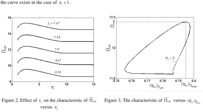
Assuming that π =15 (1≤π1≤π). Figure 2 shows the characteristic of the optimal dimensionless profit
rate (Πopt) versus π1 for different τ1. It can be seen that there exists an optimal intercooling pressure
ratio (
max 1
(π )Π ) which make Πopt reach the maximum dimensionless profit rate (Πmax). That is, there
exists a sole group of optimal heat conductance allocations (
max
(uh)Π , ( )ul Πmax, (uk)Πmax, ( )ui Πmax) and an
optimal intercooling pressure ratio (
max 1
(π )Π ) which lead to the maximum dimensionless profit rate
(Πmax). Πopt increases with the increase of τ1. The calculation illustrates that when π1 increases to a
certain value, one has ( ) 0 opt
i
u Π = , and Πopt keeps a constant.
Figure 3 shows the characteristic of Πopt versus corresponding exergy efficiency (( )
opt
ex
η Π ) with τ =1 5. It
can be seen that the characteristic of Πopt versus ( )
opt
ex
η Π is loop-shaped, there exists a maximum
dimensionless profit rate (Πmax) and the corresponding exergy efficiency ( max
(ηex)Π ). The broken line in
the curve exists in the case of π <1 1.
Figure 2. Effect of τ1 on the characteristic of Πopt
versus π1
Figure 3. The characteristic of Πopt versus ( )
opt
ex
η Π
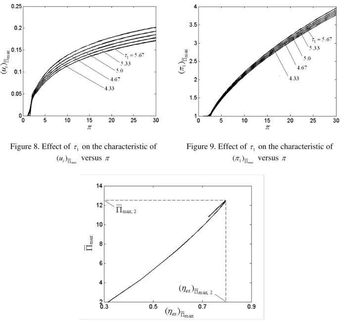
4.2 The maximum dimensionless profit rate
Figure 4 shows the characteristic of the maximum dimensionless profit rate (Πmax) versus π for different
1
τ . Figures 5-9 show the characteristics of the corresponding optimal heat conductance allocations (
max
(uh)Π , ( )ul Πmax, (uk)Πmax, ( )ui Πmax) and optimal intercooling pressure ratio ((π1)Πmax) versus π for
different τ1, respectively. Figure 10 shows the characteristic of Πmax versus the corresponding exergy
efficiency (
max
(ηex)Π ) with τ =1 5.
It can be seen from Figure 4 that there exists an optimal total pressure ratio (
max, 2
πΠ ) which make Πmax
ratio is
max, 2 1
(π )Π ). Πmax, 2 increases with the increase of τ1. It can be seen from Figures 5-9 that with the
increase of π ,
max
(uh)Π and (uk)Πmax decrease, ( )ul Πmax, ( )ui Πmax and (π1)Πmax increase. With the increase of
1 τ ,
max
(uh)Π and (uk)Πmax increase, ( )ul Πmax and ( )ui Πmax decrease, and (π1)Πmax decreases slightly. However,
when π >5, the value of
max
(uh)Π is about 0.4∼0.5, the value of ( )ul Πmax is about 0.1, the value of (uk)Πmax
is about 0.2, the value of
max
( )ui Π is about 0.1∼0.2. It can be seen from Figure 10 that the characteristic
of Πmax versus max
(ηex)Π is loop-shaped, there exists a double-maximum dimensionless profit rate (Πmax, 2)
and the corresponding exergy efficiency (
max, 2
(ηex)Π ).
Figure 4. Effect of τ1 on the characteristic of Πmax
versus π
Figure 5. Effect of τ1 on the characteristic of
max
(uh)Π versus π
Figure 6. Effect of τ1 on the characteristic of
max
( )ul Π versus π
Figure 7. Effect of τ1 on the characteristic of
max
Figure 8. Effect of τ1 on the characteristic of
max
( )ui Π versus π
Figure 9. Effect of τ1 on the characteristic of
max 1
(π )Π versus π
Figure 10. The characteristic of Πmax versus max
(ηex)Π
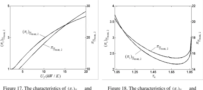
4.3 The effects of design parameters on the optimal performance Figures 11-18 show the characteristics of Πmax, 2 ,
max, 2
(ηex)Π , (π1)Πmax, 2and πΠmax, 2 versus a, b, UT and τ4
with τ =1 5, respectively. It can be seen from Figures 11-14 that Πmax, 2 increases with the increases of a,
b and UT. When UT is large, Πmax, 2 increases slowly, there exists an optimal consumer-side
temperature (( )τ4 opt) which leads to a thrice-maximum dimensionless profit rate (Πmax, 3). The
characteristics of
max, 2
(ηex)Π versus a, b and τ4 are parabolic-like, but the value of (ηex)Πmax, 2 changes
slightly with the changes of a and b. The characteristic of
max, 2
(ηex)Π versus UT is similar to that of
max, 2
Π versus UT. It can be seen from Figures 15-18 that
max, 2 1
(π )Π increases with the increases of a and
T
U . When a is large,
max, 2 1
(π )Π increases slowly,
max, 2 1
(π )Π decreases with the increase of b. The
characteristic of
max, 2 1
(π )Π versus τ4 is parabolic-like. The characteristics of πΠmax, 2 versus a, b, UT and
4
τ are similar to those of
max, 2 1
Figure 11. The characteristics of Πmax, 2 and
max, 2
(ηex)Π versus a
Figure 12. The characteristics of Πmax, 2 and
max, 2
(ηex)Π versus b
Figure 13. The characteristics of Πmax, 2 and
max, 2
(ηex)Π versus UT
Figure 14. The characteristics of Πmax, 2 and
max, 2
(ηex)Π versus τ4
Figure 15. The characteristics of
max, 2 1
(π )Π and
max, 2
πΠ versus a
Figure 16. The characteristics of
max, 2 1
(π )Π and
max, 2
Figure 17. The characteristics of
max, 2 1
(π )Π and
max, 2
πΠ versus UT
Figure 18. The characteristics of
max, 2 1
(π )Π and
max, 2
πΠ versus τ4
5. Thermal capacity rate matching between the working fluid and heat reservoirs
For the variable-temperature heat reservoirs, the thermal capacity rates of working fluid and heat reservoirs have important influence on the performances of intercooled regenerative Brayton power cycles [47, 48]. Figures 19 and 20 shows the characteristic of Πmax, 2 versus the thermal capacity rate
matching (Cwf /CL) between the working fluid and the cold-side heat reservoir for different CH /CL and
T
U with a=10, b=6, τ =1 5.0, τ =4 1.2 and CL =CI =1.2kW K/ . It can be seen that there exists an
optimal the thermal capacity rate matching ((Cwf /CL opt) ) that make Πmax, 2 reach a thrice-maximum
dimensionless profit rate (Πmax, 3). When (Cwf /CL)>(Cwf /CL opt) , Πmax, 2 decreases rapidly. When
(CH/CL)>1, the effect of CH /CL on the characteristic of Πmax, 2 versus Cwf /CL is slight. When
(CH/CL)<1, with the increase of CH /CL, (Cwf /CL opt) increases, and Πmax,3 decreases slightly. With the
increase of UT, (Cwf /CL opt) increases, Πmax,3 increases slightly.
Figure 19. The characteristic of Πmax, 2 versus
/
wf L
C C for different CH/CL
Figure 20. The characteristic of Πmax, 2 versus
/
wf L
6. Conclusion
Finite time exergoeconomic analyses is applied to perform the profit rate optimization of the CHP plant composed of an endoreversible intercooled regenerative Brayton closed-cycle coupled to variable-temperature heat reservoirs. The results show that the optimal heat conductance allocation of the regenerator is always zero at the design point of the optimal dimensionless profit rate. When the total pressure ratio, the heat conductance allocation of the regenerator and the total heat conductance are fixed, there exists a sole group of optimal heat conductance allocations among the hot-, cold- and consumer-side heat exchangers and the intercooler, and an optimal intercooling pressure ratio which lead to the maximum dimensionless profit rate. When the total pressure ratio is changeable, there exists an optimal total pressure ratio and an optimal intercooling pressure ratio which lead to a double-maximum dimensionless profit rate, and one can obtain that the value of
max
(uh)Π is about 0.4∼0.5, the value of
max
( )ul Π is about 0.1, the value of (uk)Πmax is about 0.2, and the value of ( )ui Πmax is about 0.1∼0.2,
respectively. The characteristic of the maximum dimensionless profit rate versus the corresponding exergy efficiency is studied and the characteristic is loop-shaped. The effects of some design parameters on the double-maximum dimensionless profit rate and the corresponding exergy efficiency, optimal total pressure ratio and optimal intercooling pressure ratio are discussed in detail. It is found that there exists an optimal consumer-side temperature which lead to a thrice-maximum dimensionless profit rate. When the optimization is performed additionally with respect to the thermal capacitance rate matching between the working fluid and the heat reservoirs, a thrice-maximum profit rate is obtained.
Acknowledgements
This paper is supported by The National Natural Science Foundation of P. R. China (Project No. 10905093), The Program for New Century Excellent Talents in University of P. R. China (Project No. NCET-04-1006) and The Foundation for the Author of National Excellent Doctoral Dissertation of P. R. China (Project No. 200136).
Nomenclature
a price ratio of power output to exergy input rate
b price ratio of thermal exergy output rate to exergy input rate C heat capacity rate (kW K/ )
E effectiveness of the heat exchanger e exergy flow rate (kW)
k ratio of the specific heats N number of heat transfer units
P power output of the cycle (kW )
Q rate of heat transfer (kW) s entropy (kJ K/ )
T temperature (K)
U heat conductance (kW K/ )
h
u hot-side heat conductance allocation
i
u heat conductance allocation of the intercooler
k
u consumer-side heat conductance allocation
l
u cold-side heat conductance allocation
r
u heat conductance allocation of the regenerator
x isentropic temperature ratio for low-pressure compressor
y isentropic temperature ratio for total compression process
Greek symbols
ϕ price of exergy flow rate (dollar kW/ )
η efficiency
Π profit rate (dollar)
1
π intercooling pressure ratio
π total pressure ratio
1
τ ratio of the inlet temperature of hot-side heat reservoir to environment temperature
2
τ ratio of the inlet temperature of cold-side heat reservoir to environment temperature
3
τ ratio of the inlet temperature of intercooling fluid to environment temperature
4
τ ratio of the consumer-side temperature to environment temperature Subscripts
ex exergy
H hot-side
I intercooler
in inlet
K consumer-side
L cold-side
max maximum
min minimum
opt optimal
out outlet
R regenerator
T total
wf working fluid
0 ambient
1, 2, 3, 4, 5, 6, 7,8, 9 state points of the cycle dimensionless
References
[1] Habib M A. Thermodynamic analysis of the performance of cogeneration plants. Energy, The Int. J., 1992, 17(5): 485-491.
[2] Rosen M A, Le M N, Dincer I. Exergetic analysis of cogeneration-based district energy systems. Proc. IMechE, Part A: J. Power Energy, 2004, 218(6): 369-375.
[3] Khaliq A. Exergy analysis of gas turbine trigeneration system for combined production of power heat and refrigeration.
Int. J. Refrig., 2009, 32(3): 534-545.
[4] Reddy B V, Butcher C.
Second law analysis of a natural gas-fired gas turbine cogeneration
system.
Int. J. Energy Res., 2009, 39(8): 728-736.[5] Khaliq A, Choudhary K. Thermodynamic evaluation of gas turbines for cogeneration applications. Int. J. Exergy, 2009, 6 (1): 15-33.
[6] Andresen B. Finite Time Thermodynamics. Physics Laboratory II, University of Copenhagen, 1983.
[7] Bejan A. Entropy generation minimization: The new thermodynamics of finite-size devices and finite-time process. J. Appl. Phys., 1996, 79(3): 1191-1218.
[8] Berry R S, Kazakov V A, Sieniutycz S, Szwast Z, Tsirlin A M. Thermodynamic Optimization of Finite Time Processes. Chichester: Wiley, 1999.
[9] Chen L, Wu C, Sun F. Finite time thermodynamic optimization of entropy generation minimization of energy systems. J. Non-Equilibrium Thermodyn., 1999, 24(4): 327-359.
[10] Durmayaz A, Sogut O S, Sahin B and Yavuz H. Optimization of thermal systems based on finite-time thermodynamics and thermoeconomics. Progr. Energy Combus. Sci., 2004, 30(2): 175-217. [11] Chen L, Sun F. Advances in Finite Time Thermodynamics: Analysis and Optimization. New
York: Nova Science Publishers, 2004.
[12] Ust Y, Sahin B, Safa A. Ecological performance analysis of an endoreversible regenerative Brayton heat-engine. Appl. Energy, 2005, 80(3): 247-260.
[13] Ust Y, Sahin B, Kodal A. Performance analysis of an irreversible Brayton heat engine based on ecological coefficient of performance criterion. Int. J. Thermal Sci., 2006, 45(1): 94-101.
[15] Ust Y, Sahin B, Kodal A, Akcay I H. Ecological coefficient of performance analysis and optimization of an irreversible regenerative Brayton heat engine. Appl. Energy, 2006, 83(6): 558-572.
[16] De Vos A. Thermodynamics of Solar Energy Conversion. Berlin: Wiley-Vch, 2008. [17] Feidt M. Optimal thermodynamics-New upperbounds. Entropy, 2009, 11(4): 529-547.
[18] Sieniutycz S, Jezowski J. Energy Optimization in Process Systems. Elsevier, Oxford, UK, 2009. [19] Bojic M. Cogeneration of power and heat by using endoreversible Carnot engine. Energy Convers.
Mgmt., 1997, 38(18): 1877-1880.
[20] Sahin B, Kodal A, Ekmekci I, Yilmaz T. Exergy optimization for an endoreversible cogeneration cycle. Energy, The Int. J., 1997, 22(5): 551-557.
[21] Erdil A. Exergy optimization for an irreversible combined cogeneration cycle. J. Energy Instit., 2005, 75(1): 27-31.
[22] Atmaca M, Gumus M, Inan A T, Yilmaz T. Optimization of irreversible cogeneration systems under alternative performance criteria. Int. J. Thermophys., 2009, 30(5): 1724-1732.
[23] Ust Y, Sahin B, Kodal A. Performance optimisation of irreversible cogeneration systems based on a new exergetic performance criterion: exergy density. J. Energy Instit., 2009, 82(1): 48-52. [24] Yilmaz T. Performance optimization of a gas turbine-based cogeneration system. J. Phys. D: Appl.
Phys., 2006, 39(11): 2454-2458.
[25] Hao X, Zhang G.
Maximum useful energy-rate analysis of an endoreversible Joule-Brayton
cogeneration cycle. Appl. Energy, 2007, 84(11): 1092-1101.
[26] Hao X, Zhang G. Exergy optimisation of a Brayton cycle-based cogeneration plant. Int. J. Exergy, 2009, 6(1): 34-48.
[27] Ust Y, Sahin B, Yilmaz T. Optimization of a regenerative gas-turbine cogeneration system based on a new exergetic performance criterion: exergetic performance coefficient. Proc. ImechE, Part A: J. Power Energy, 2007, 221(4): 447-458.
[28] Ust Y, Sahin B, Kodal A.
Optimization of a dual cycle cogeneration system based on a new
exergetic performance criterion. Appl. Energy, 2007, 84(11): 1079 -1091.
[29] Tsatsaronts G. Thermoeconomic analysis and optimization of energy systems. Progr. Energy Combus. Sci., 1993, 19(3): 227-257.
[30] El-Sayed M. Thermoeconomics of Energy Conversion. London: Elsevier, 2003.
[31] Salamon P, Nitzan A. Finite time optimizations of a Newton's law Carnot cycle. J. Chem. Phys., 1981, 74(6): 3546-3560.
[32] Chen L, Sun F, Chen W. The relation between optimal efficiency and profit rate of a Cannot engine. J. Engng. Thermal Energy Power, 1991, 6(4): 237-240 (in Chinese).
[33] Sun F, Chen L, Chen W. The efficiency and profit holographic spectrum of a two-heat-reservoir heat engine. Trans. Chin. Soc. Internal Combus. Engines, 1991, 9(3): 286-287 (in Chinese).
[34] Chen L, Sun F, Wu C. Exergoeconomic performance bound and optimization criteria for heat engines. Int. J. Ambient Energy, 1997, 18(4): 216-218.
[35] Wu C, Chen L, Sun F. Effect of heat transfer law on finite time exergoeconomic performance of heat engines. Energy, The Int. J., 1996, 21(12): 1127-1134.
[36] Chen L, Sun F, Chen W. Finite time exergoeconomic performance bound and optimization criteria for two-heat-reservoir refrigerators. Chin. Sci. Bull., 1991, 36(2): 156-157 (in Chinese).
[37] Chen L, Wu C, Sun F. Effect of heat transfer law on finite time exergoeconomic performance of a Carnot refrigerator. Exergy, An Int. J., 2001, 1(4): 295-302.
[38] Wu C, Chen L, Sun F. Effect of heat transfer law on finite time exergoeconomic performance of a Carnot heat pump. Energy Convers. Mgnt., 1998, 39(7): 579-588.
[39] Zheng Z, Chen L, Sun F, Wu C. Maximum profit performance for a class of universal steady flow endoreversible heat engine cycles. Int. J. Ambient Energy
, 2006, 27(1): 29-36.
[40] Chen L, Sun F, Wu C. Maximum profit performance for generalized irreversible Carnot engines. Appl. Energy, 2004, 79(1): 15-25.
[41] Chen L, Zheng Z, Sun F, Wu C. Profit performance optimisation for an irreversible Carnot refrigeration cycle. Int. J. Ambient Energy,2008, 29(4): 197-206.
[43] Tao G, Chen L, Sun F. Exergoeconomic performance optimization for an endoreversible regenerative gas turbine closed-cycle cogeneration plant. Riv. Mex. Fis., 2009, 55(3): 192-200. [44] Chen L, Yang B, Sun F. Exergoeconomic performance optimization of an endoreversible
intercooled regenerated Brayton cogeneration plant. Part 1: thermodynamic model and parameter analyses. Int. J. Energy and Environment, 2011, 2(2): 199-210.
[45] Yang B, Chen L, Sun F. Exergoeconomic performance optimization of an endoreversible intercooled regenerated Brayton cogeneration plant. Part 2: heat conductance allocation and pressure ratio optimization. Int. J. Energy and Environment, 2011, 2(2): 211-218.
[46] Yang B, Chen L, Sun F. Exergoeconomic performance analyses of an endoreversible intercooled regenerative Brayton cogeneration type model. Int. J. Sustainable Energy, 2011, 30(2): 65-81. [47] Wang W, Chen L, Sun F, Wu C. Power optimization of an endoreversible closed intercooled
regenerated Brayton cycle coupled to variable-temperature heat reservoirs. Appl. Energy, 2005, 82(2): 181-195.
[48] Wang W, Chen L, Sun F, Wu C. Efficiency optimization of an irreversible closed intercooled regenerated gas-turbine cycle. Proc. IMechE, Part A: J. Power Energy, 2006, 220(A6): 551-558. [49] Chen L, Wang J, Sun F. Power density optimisation of an endoreversible closed intercooled
regenerated Brayton cycle. J. Energy Instit., 2007, 80(2): 105-109.
[50] Fang G, Cai R, Lin R. Analysis on basic parameters in cogeneration cycle with gas turbine and steam turbine. J. Power Engng., 1998, 8(6): 118-124 (in Chinese).
Bo Yang received his BS Degree in 2008 and MS Degree in 2010 in power engineering and engineering
thermophysics from the Naval University of Engineering, P R China. He is pursuing for his PhD Degree in power engineering and engineering thermophysics of Naval University of Engineering, P R China. His work covers topics in finite time thermodynamics and technology support for propulsion plants. Dr Yang is the author or co-author of 11 peer-refereed articles (5 in English journals).
Lingen Chen received all his degrees (BS, 1983; MS, 1986, PhD, 1998) in power engineering and
engineering thermophysics from the Naval University of Engineering, P R China. His work covers a diversity of topics in engineering thermodynamics, constructal theory, turbomachinery, reliability engineering, and technology support for propulsion plants. He has been the Director of the Department of Nuclear Energy Science and Engineering, the Director of the Department of Power Engineering and the Superintendent of the Postgraduate School. Now, he is the Dean of the College of Naval Architecture and Power, Naval University of Engineering, P R China. Professor Chen is the author or co-author of over 1200 peer-refereed articles (over 520 in English journals) and nine books (two in English).
E-mail address: [email protected]; [email protected], Fax: 83638709 Tel: 0086-27-83615046
Fengrui Sun received his BS degree in 1958 in Power Engineering from the Harbing University of
![Figure 1. T-s diagram for the cycle process 3. The profit rate and exergy efficiency analytical formulae [46]](https://thumb-eu.123doks.com/thumbv2/123dok_br/17049199.234124/4.892.294.617.620.898/figure-diagram-process-profit-exergy-efficiency-analytical-formulae.webp)