THERMAL EXPANSION BEHAVIOR OF CO-EXTRUDED
WOOD-PLASTIC COMPOSITES WITH GLASS-FIBER REINFORCED
SHELLS
Runzhou Huang,a Wen Xiong,b Xinwu Xu,a and Qinglin Wu a,c,*
Coextruded wood-plastic composites (WPCs) with glass-fiber (GF) filled shells were manufactured, and their thermal expansion behavior was studied. A three-dimensional finite element model (FEM) considering differential properties of both shell and core layers was developed to predict the linear coefficient of thermal expansion (LCTE) of the material. It was shown that the LCTE values varied with composite structure and composition (i.e., core-shell thicknesses and materials). The use of GF-filled shells helped lower overall composite LCTE values. The imbalance of shell and core LCTE, and their moduli led to complex stress fields within a given composite system. The FEM predicted a trend of LCTE change with varying composite structures, which was in good agreement with the experimental data. This study provides for the first time a finite element modeling technique to optimize raw material composition and composite structure for optimizing thermal expansion behavior of co-extruded WPCs.
Keywords: Thermal expansion; WPC; Co-extrusion; Core shell; Modeling
Contact information: a: College of Wood Science and Technology, Nanjing Forestry University, Nanjing, 210037; b: Department of Bridge Engineering, School of Transportation, Southeast University, Nanjing, 210096, China; c: School of Renewable Natural Resources, Louisiana State University Agriculture Center, Baton Rouge, Louisiana 70803, USA. * Corresponding author: E-mail: [email protected]
INTRODUCTION
Co-extruded wood-plastic composites (WPCs) with a core-shell structure have recently been developed and used to enhance performance characteristics of WPCs (Yao and Wu 2010; Stark and Matuana 2007). The shell layer, made of thermoplastics unfilled or filled with minerals and other additives, plays a critical role in enhancing the overall composite properties. Investigations have been done to develop a stabilized shell layer by blending high-density polyethylene (HDPE) and additives including a compatibilizer, a photostabilizer, and a nanosized TiO2 in the co-extruded WPC (Jin and Matuana 2010) by
using combined wood and mineral fillers (Yao and Wu 2010). In the shell layer, carbon nano-tube (Jin and Matuana 2010) and precipitated calcium carbonate (Kim 2012) have also been used. With a proper combination of constituting layers, one can achieve a balance of such properties as low weight, high strength, high stiffness, wear resistance, biological resistance, unusual thermal expansion characteristics, appearance, etc. A fundamental understanding of the interactions between shell and core layers with different structural (e.g., thickness) and material combinations is, however, needed to achieve desired product performance.
caused by external temperature variations are considered to be some of the most important performance properties for WPC (Singh and Mohanty 2007; Klyosov 2007). Layered composites are particularly suitable for structural material when low thermal expansion properties are required (Jones 1975). Some high-strength fiber materials (e.g., glass fibers, GFs) show a very low or even negative linear coefficient of thermal expansion (LCTE). Therefore, by embedding these fibers in the composite matrix, which has a high and positive LCTE, it is possible to obtain a material with satisfactory mechanical characteristics and low LCTE (Zhu and Sun 2003). The developed materials can then be used as shell or core layers in co-extruded WPC to control overall composite thermal expansion.
The thermal expansion behavior of laminated composites can be analyzed following an approach based on classical lamination theory, CLT (e.g., Hsueh and Ferber 2002; Jones 1975; Halpin and Pagnao 1969). Halpin and Pagano (1969) studied the deformation of a laminate induced by swelling due to the effect of uniform temperature changes. Bressan et al. (2004) presented a procedure for the design of structural laminates made of carbon-epoxy with low thermal expansion. The influence of material characteristics and process parameters on the thermal expansion behavior was assessed using lamination theory. Yu and Zhou (2010) presented an integrated thermo-mechanical method for modeling the behavior of fiber-reinforced polymer composite structures subject to simultaneous fire and mechanical load. The model included heat transfer modeling to calculate temperature history of the structure and structural modeling to predict the mechanical performance of the structure using finite element models (FEMs). However, very little work has been done in modeling the thermal expansion behavior of WPC, especially extruded WPC. Furthermore, CLT cannot be directly applied to co-extruded composite material with a fully capped shell layer, due to the restraining effect of the composite shell. Thus, a numerical approach is needed for such composite systems.
The objectives of this study were: 1) to investigate the effects of various GF contents in the shell layer and shell thickness changes on thermal expansion properties of co-extruded WPC in combination with two core systems, 2) to develop a finite element modeling procedure for predicting thermal performance of the composites, and 3) to verify the model prediction of LCTE with experimental data.
EXPERIMENTAL
Raw Materials and Preparation
Struktol Co. (Stow, OH, USA) was also used to improve the processing of WPC profile. The mixtures of HDPE and R-LDPE were used as base resins to make two core systems. HDPE, 40% GF-filled HDPE and/or their mixtures were used to make a shell material as a function of GF content. Materials used for shells were used without pre-compounding to prevent further breakage of GF fibers.
Co-extruded WPC Manufacturing
The composites were formulated with two core types in combination with different GF contents and thicknesses in a shell layer for each core type. The formulations for the two-core systems were, respectively, R-LDPE: HDPE: WF: Lubricant: MAPE = 30: 10: 50: 6: 4 wt%, and R-LDPE: HDPE: WF: Lubricant: MAPE = 10: 30: 50: 6: 4 wt%. Five GF content levels (i.e., 0, 10, 20, 30, and 40 wt% of the total shell weight) and five shell thicknesses (i.e., 0.8, 1.0, 1.2, 1.4, and 1.6 mm) were used to make different shells.
The composites were manufactured with a pilot-scale co-extrusion system (Yao and Wu 2010). This system consisted of a Leistritz Micro-27 co-rotating parallel twin-screw extruder (Leistritz Corporation, Allendale, NJ) for the core and a Brabender 32 mm conical twin-screw extruder (Brabender Instruments Inc., South Hackensack, NJ, USA) for the shell. A specially designed die with a cross-section area of 12.5 x 50.4 mm was used. A vacuum sizer was used to maintain the targeted size. The co-extruded profiles were passed through a 2 m water bath with water spraying using a down-stream puller. Manufacturing temperatures for the core were controlled at 155 (feeder), 160, 165, 170, 170, 170, 160, 150, 140, 130, and 155 °C (die). Manufacturing temperatures for shells varied from 150 to 165 °C in the variation of different shell formulations. Different shell thicknesses were achieved by controlling shell material feeding rate and extrusion speed.
Thermal Expansion Measurements
The LCTE value of each specimen was measured parallel to the extrusion direction over a temperature range from 25 to 60 °C. The specimens had a long dimension of 76 ± 9 mm along the extrusion direction. They were conditioned in an oven at 60 °C for 6 hours from their initial equilibrium temperature of 25 °C prior to size measurements with a Mitutoyo digimatic indicator of ±0.01 mm accuracy (Mitutoyo Co.,
Kanagawa, Japan). Five specimens were used for each group. The LCTE for each sample was calculated based on size changes before and after conditioning.
FINITE ELEMENT MODELING
Basic Equations
The general stress and strain relationship for linear elastic material is expressed as (Melicher et al. 2007),
]) [ ] ]([ [ ] ][ [ ]
[ E EL E TH
(1)
where [σ] is the stress vector,
T zz yy xx zz yy
xx ]
[ ]
[
[ε] is the total deformation vector, [εTH] is the deformation vector from temperature change, and [E] is the elasticity matrix.
T zz yy xx zz yy xx ] [ ] [ (3)
By Equation (1), we obtain:
] [ ] [ ] [ ]
[ TH E 1
(4)
For the three-dimensional case, the thermal strain tensor is expressed as,
T z
y x
TH] T[ 0 0 0]
[
(5)
where αx αy, and αz are, respectively, thermal coefficients of expansion in x, y, and z
direction, T = (T-TREF) with T as current temperature. The elasticity matrix is
11/ / / 0 0 0
/ 1/ / 0 0 0
/ / 1/ 0 0 0
0 0 0 1/ 0 0
0 0 0 0 1/ 0
0 0 0 0 0 1/
xx xy xx xz xx
yx yy yy yz yy
zx zz zy zz zz
xy
yz
xz
E E E
E E E
E E E
E G G G (6)
where Exx, Eyy, and Ezzare Young’s moduli in the x, y, and z directions, νxx, νyy, and νzz
are Poisson’s ratios, and Gxy, Gyz, and Gxz are shear moduli in xy, yz, and xz planes. If it
is assumed that [E-1] is symmetric, then
yy yz zz zy xx xz zz zx xx xy yy yx E E ; E E E E ; (7)
For the anisotropic case, the elasticity matrix [E] includes 21 independent coefficients. For orthotropic material, the elasticity matrix [E] includes only 9 independent coefficients. The isotropic material has two independent material constants defined by the following equation:
2(1)
E
G
Finite Element Model
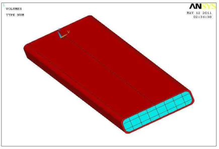
The commercial finite element code ANSYS Version 10 (ANSYS Inc. Canonsburg, PA, USA) was used for the numerical analysis of thermal expansion behavior of the extruded WPC. For simplicity, an isotropic material for both core and shell layers was assumed in the analysis. A typical geometrical model is shown in Fig. 1. The composites had a core-shell structure with an overall cross-section dimension of 12.5 x 50.4 mm. During simulation runs, the shell thickness and material type were varied with two different core systems with step-wise, steady state temperature increases throughout the composite system.
Fig. 1.Geometric model for coextruded wood plastic composites
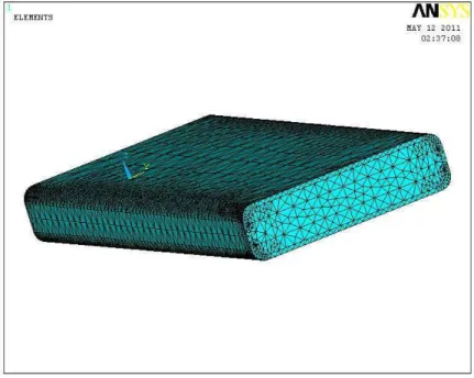
The finite element mesh (Fig. 2) was developed using Solid 64 for both core and shell materials with 8 nodes and 3 degrees of freedom at each node. Finer meshes were developed in the four corners of the composite. The model was solved with a precon-ditioned conjugate gradient (PCG) iterative equation solver available in ANSYS. Post-processing involved graphical plots for geometry, strain and stress fields, and numerical value output.
Material Properties
with an increase of glass fiber content from 0 (S1) to 40% (S5), indicating a large restricting effect of the GFs on the plastic matrix thermal expansion.
Fig. 2.Finite element mesh (bottom) for co-extruded wood plastic composites
Table 1. Summary of Material Properties at 20°C Temperature Used in FE Simulation
Material Type Young’s
modulus (MPa) Poisson Ratio Shear modulus (MPa) LCTE (10-5/°C)
Core Core I
Core II 2,160 3,230 0.34 0.34 802 1205 8.0 5.5 Shell
S1 (0% GF) S2 (10% GF) S3 (20% GF) S4 (30% GF) S5 (40% GF)
850 1,300 2,300 3,600 5,800 0.34 0.34 0.34 0.34 0.34 317 485 858 1,343 2,164 14.0 9.0 6.0 4.0 2.0
The effect of temperature on Young’s modulus (E, MPa) for both core and shell layers was estimated in the model using the following equations (Vos 1998; Haneef et al.
2011): )] 20 ( 0155 . 0 1 [ ) 20 ( ) ( )] 20 ( 0143 . 0 1 [ ) 20 ( ) ( T C E T E T C E T E o SHELL SHELL o CORE CORE (9)
RESULTS AND DISCUSSION
Predicted Thermal Stresses
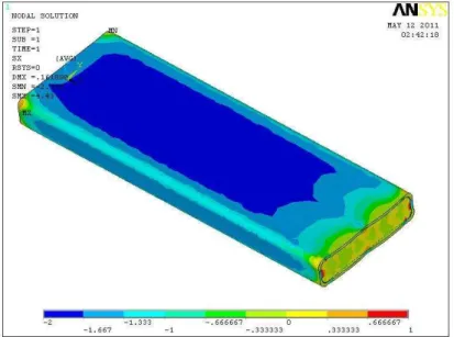
Figure 3 shows a typical graphical plot of a predicted stress field in the co-extruded WPC due to temperature change and mismatch of thermal expansion behavior between core and shell layers in the composites.
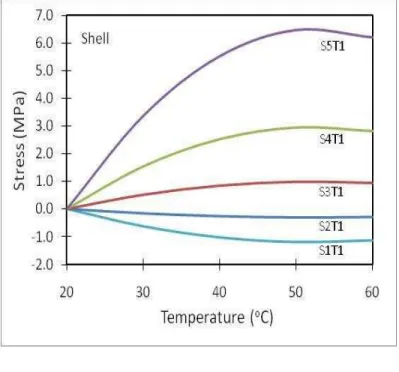
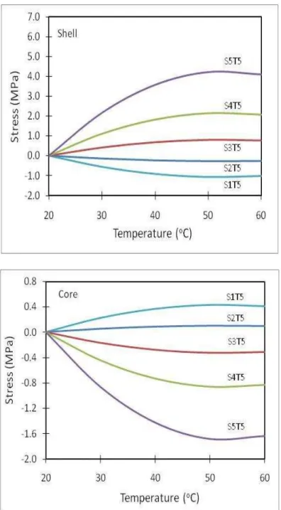
The HDPE shell (S1) had a larger LCTE value compared with that of the core layer. As the temperature increased, the HDPE shell tried to expand more, but was restricted by the core layer. As a result, the shell was put under compression (Fig. 3 and shell - S1T1 in Fig. 4), and as a reaction, the core was put under tension (Fig. 3 and core - S1T1 in Fig. 4). The magnitude of both compression and tensile stresses depended on the range of temperature changes and differences in LCTE and elastic moduli between core and shell layers for the given composites. Due to a symmetrical design of the composite, the stress distribution respect to the board center was balanced, and the thermal stresses did not cause any warping of the composite (Fig. 3). However, one common practice in co-extruded WPC is not to cap the bottom surface. This practice could lead to an imbalanced thermal stress field within the material, resulting in warping of the composites with temperature changes.
Fig. 3.Predicted thermal stress fields of co-extruded WPCs with temperature changes from 20 to 40 °C. Core II composite with HDPE shell (S1) at shell thickness T3 = 1 mm
core I composites) had a similar general thermal stress behavior, except for different stress mode of the shell 3 system. The LCTE value for shell 3 was larger than the core II LCTE value. The shell 3 in the core II composite system was under compression and its corresponding core was in a state of tension as temperature increased.
The thermal stresses developed may have an influence on the stability of core-shell interface in the composite. Also, any imbalance of the stresses can cause the composite to warp under the thermal load.
Fig. 4.Predicted shell and core stress distributions as a function of temperature increase for core I system (S1, S2, S3, S4, and S5 represent shells filled with 0, 10, 20, 30, and 40% GF,
Fig. 5.Predicted shell and core stress distributions as a function of temperature increase for core I system ((S1, S2, S3, S4, and S5 represent shells filled with 0, 10, 20, 30, and 40% GF,
respectively, as defined in Table 1, and T1 represents a shell thickness of 1.6 mm)
Predicted Thermal Strains
Fig. 6.Predicted thermal strain fields of co-extruded WPCs with temperature changes from 20 to 40 °C. Core II composite with shell HDPE (shell 1) at shell thickness T3 = 1 mm
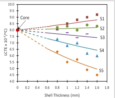
Figures 7 and 8 show predicted LCTE values of co-extruded WPC as a function of shell thickness and modulus for core I (E = 2.26 GPa; LCTE = 8.0x10⁻⁵/°C) and II (E = 3.26 GPa; LCTE = 5.5x10⁻⁵/°C) systems, respectively, in comparison with the experimental LCTE data. It was shown that LCTE values of the co-extruded WPC varied almost linearly with changes in the shell layer thickness. When the shell LCTE value was greater than the core LCTE (S1/S2 for core I system and S1/S2/S3 for core II system), an increase in shell thickness led to increased overall composite LCTE. As such, thin shells were preferred for such composites.
Fig. 8.Predicted LCTE values of co-extruded WPC as a function of shell thickness and modulus for core II (E = 3.26 GPa; LCTE = 5.5x10⁻⁵/°C) composite system in comparison with
experimental data
When the shell LCTE value was smaller than the core LCTE (S3/S4/S5 for core I system and S4/S5 for core II system), an increase in shell thickness led to decreased overall composite LCTE. Thick shells were preferred for minimizing the overall composite LCTE for these composites. The predicted lines converged at the core LCTE value for each system when the shell thickness approached zero (i.e., core-only composites). The use of strong shells with low LCTE values (e.g., shell 5 with 40% GF) helped lower overall composite LCTE, especially for the core I system with a large LCTE value.
A comparison of the experimental LCTE data (symbols) with the model prediction (lines) showed a good agreement between the two, considering the complexity of extruded materials with various fillers, lack of material constants, and linear elastic assumption of modeling. Thus, the finite element modeling approach provides a way to optimize raw material composition and composite structure to minimize thermal expansion behavior of co-extruded WPC.
CONCLUSIONS
1. Co-extruded wood-plastic composites (WPCs) with glass-fiber (GF) filled shells were manufactured, and their thermal expansion coefficients were evaluated.
2. The measured LCTE values varied with composite structure and composition (i.e., core-shell thicknesses and materials). The use of GF-filled shells helped to lower the overall composite LCTE values.
4. A three-dimensional finite element model based on linear isotropic material for both shell and core was developed to predict LCTE of the material.
5. The model predicted a trend that was in a good agreement with the experimental data, which provides a way to optimize raw material composition for minimizing thermal expansion behavior of WPC.
ACKNOWLEDGEMENTS
The authors would like to acknowledge financial support from the Louisiana Board of Regents (Contract Number: LEQSF-EPS (2011)-OPT-IN-04) and Nanjing Forestry University, Nanjing, China, and Dr. Fei Yao and Dr. Birm Jun Kim for helping with sample manufacturing.
REFERENCES CITED
Bressan, F., DeBona, F., and Soma, A. (2004). “Design of composite laminates with low thermal expansion,”J. Materials: Design and Applications 218, 201-209.
Halpin, J. C., and Pagano, N. J. (1969). “The laminate approximation for randomly oriented fibrous composites,”J. Composite. Material. 3(4), 720-724.
Haneef, M., Shabbir, A. R. M., and Ali, M. M. (2011). “Studies on delaminating effects
on stress development in composite structures,”World Congress on Engineering 2011 Vol III, July 6 - 8, 2011, London, U.K.
Hsueh, C. H., and Ferber, M. K. (2002). “Apparent coefficient of thermal expansion and residual stresses in multilayer capacitors,” Composites Part A 33, 1115-1121.
Huang, R. Z. (2012). “Thermal expansion and mechanical properites of co-extruded wood plastic composites,” Ph.D Dissertation, Nanjing Forestry University, Nanjing, China.
Jin, S., and Matuana, L. M. (2010). “Wood/plastic composites co-extruded with multi-walled carbon nanotube-filled rigid poly(vinyl chloride) cap layer,” Polymer International 59, 648-657.
Jones, R. M. (1975). Mechanics of Composite Materials, McGraw-Hill, New York, USA. Kim, B. J. ( 2012). “The effect of inorganic fillers on the properties of wood plastic
composites,” Ph.D Dissertation, School of Renewable Natural Resources, Louisiana State University, Baton Rouge.
Klyosov, A. A. (2007). Wood-Plastic Composites, John Wiley & Sons Inc, Hoboken, New Jersey.
Melicher, R. J., Mesko, P. N., and Zmindak, M. (2007). “Residual stress simulation of circumferential welded joints,”Applied and Computational Mechanics 1, 541-548. Singh, S., and Mohanty, A. (2007). “Wood fiber reinforced bacterial bioplastic
composites: Fabrication and performance evaluation,”Composite Science and Technology 67, 1753-1763.
Stark, N. M., and Matuana, L. M. (2007). “Coating WPCs using co-extrusion to improve
durability,”Conference for Coating Wood and Wood Composites: Designing for Durability, Seattle, WA, 1-12.
Thesis, University of Wisconsin - Madison.
Yao, F., and Wu, Q. (2010). “Coextruded polyethylene and wood-flour composite: Effect of shell thickness, wood loading, and core quality,”J. Applied Polymer Science 118, 3594-3601.
Yu, Z., and Zhou, A. (2010). “An integrated thermomechanical method for modeling fiber reinforced polymer composite structures in fire,” ASCE Analysis and Computation Specialty Conference, 492-503.
Zhu, R. P., and Sun, C. T. (2003). “Effects of fiber orientation/elastic constants on
coefficients of thermal expansion in laminates,”Mech. Adv. Mater. Struct. 10, 99-107.