E
NERGY AND
E
NVIRONMENT
Volume 6, Issue 4, 2015 pp.331-346
Journal homepage: www.IJEE.IEEFoundation.org
Minimum energy requirement of an endoreversible
desalination system of sea water
Lingen Chen
1,2,3, Liwei Shu
1,2,3, Yanlin Ge
1,2,3, Fengrui Sun
1,2,31 Institute of Thermal Science and Power Engineering, Naval University of Engineering, Wuhan,
430033, P. R. China.
2 Military Key Laboratory for Naval Ship Power Engineering, Naval University of Engineering, Wuhan,
430033, P. R. China.
3 College of Power Engineering, Naval University of Engineering, Wuhan 430033, P. R. China.
Abstract
A model of a typical endoreversible desalination system of sea water is established and the minimum energy requirement for the system is optimized by using finite time thermodynamic theory. The heat exchange between the endoreversible desalination system of sea water and surroundings are delivered by two endoreversible Carnot heat pumps and three endoreversible Carnot heat engines. The minimum energy requirement for the system can be found by subtracting the power outputs from the power inputs. The results show that the minimum energy requirement for the distillation system depends on not only the properties of the input saline water, the output pure water and the brine water, but also the inherent features of the heat pumps and the heat engines, i.e. the total heat conductance of the heat pumps and of the heat engines. The results obtained herein are closer to those of practical system than those obtained based on reversible model.
Copyright © 2015 International Energy and Environment Foundation - All rights reserved.
Keywords: Desalination system of sea water; Endoreversible, Heat pump; Heat engine; Energy requirement; Finite time thermodynamics.
1. Introduction
pumps. The reversible Carnot heat pumps supply heat to the incoming saline water and the evaporator, and the reversible Carnot heat engines extract heat from the condenser and brine. The minimum work requirement for the desalination system of sea water was obtained by using the first and second-laws of thermodynamics.
Since 1970s, the investigation on the performance characteristics of thermodynamic processes and optimization of thermodynamic cycles has made tremendous progress from classical to quantum processes by scientists and engineers by using finite time thermodynamics [7-13]. Finite time thermodynamics is also a powerful tool for performance analysis and optimization for various separation processes and devices[14, 15]. Nulton et al [16] addressed a number of questions related to the efficient integration network of heat with finite conductance and an endoreversible heat engine whose working fluid undergo a cycle custom designed to match the utility demands. The minimum exergy cost of supplying the utility demand to a heat exchange network was calculated particularly. The results give a simple measure of potential exergy savings from incorporating active elements into the network. Brown et al [17] optimized the performance of a porous plug separation system by taking ‘‘turnpike’’ (i.e., boundary-singular-boundary branch) trajectory. The minimum work required to move the plug from one equilibrium position to another equilibrium position in a given time period was optimized. And the lower bound for the separation of gases by diffusion was obtained. Tsirlin et al [18-22] derived the new thermodynamic limits on the performance of irreversible separation processes, including work of separation in finite time (a generalization of Van’t Hoff reversible work of separation for finite rate processes), maximum productivity of heat-driven binary separation process, the minimum average dissipation and the ideal operating line in an irreversible distillation column. The minimum dissipation level and the distillation column’s maximum productivity are achieved by realizing the ideal operating line for the profiles of heat supply/removal. The total entropy production of a fully diabatic distillation column with heat transfer effects was minimized by Schaller et al [23]. Shu et al [24] put bounds on the overall heat exchange and researched the optimal allocation of the heat exchanger inventory for the sequential heat exchangers in the diabatic distillation column. The optimal allocation of the heat exchanger inventory for the sequential heat exchangers was obtained and the optimal performance of the diabatic distillation column was achieved.
A typical endoreversible desalination system model of sea water is established in this paper based on Ref. [6] by using the fundamental theory and method of finite time thermodynamics. The reversible heat pumps in Ref. [6] are replaced by endoreversible heat pumps and the reversible heat engines in Ref. [6] are replaced by endoreversible heat engines in the developed model. The heat transfer between the endoreversible distillation system and surroundings are delivered by the endoreversible Carnot heat pumps and endoreversible Carnot heat engines. The minimum energy requirement for the distillation system is analyzed and optimized. The effects of pure water recovery ratio and the mole fraction of salt in incoming saline water on the minimum energy requirement are discussed.
2. Endoreversible desalination system of sea water
Carnot heat engine, thus producing power. The latent heat of condensation of the pure water is absorbed by the fourth endoreversible Carnot heat engine connected to the condenser. The pure water at TL is then routed into the heat exchanger to be cooled by the incoming saline water. On the other hand, the brine leaves the evaporator at temperature TH and transfers heat to the fifth endoreversible Carnot heat engine as it is cooled from TH to TL, producing power.
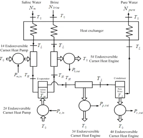
Figure 1. The schematic diagram of endoreversible distillation system
It can be seen from Figure 1 that the heat transfer between the endoreversible distillation system and surroundings are delivered by the two endoreversible Carnot heat pumps and the three endoreversible Carnot heat engines. The first endoreversible Carnot heat pump operates with variable-temperature heat sink and constant-temperature heat source. The second endoreversible Carnot heat pump operates with constant-temperature heat sink and constant-temperature heat source. The third and fifth endoreversible Carnot heat engines operate with variable-temperature heat sources and constant-temperature heat sinks. And the fourth endoreversible Carnot heat engine works with constant-temperature heat source and constant-temperature heat sink.
The main assumptions for endoreversible distillation system are:
(1) All components of the system operate steadily. The components of the system are well insulated. All heat transfers with the surroundings are through the endoreversible heat engines and heat pumps.
(2) The salinity of the incoming seawater is constant. No changes in kinetic and potential energies of the fluids occur as they circulate through the system. The fluid flow is inviscid, and thus there are no pressure drops.
(3) Liquid water is an incompressible substance with constant specific heats. The temperatures of the incoming saline water and the surroundings are
T
0. The saline water is an ideal solution.temperature heat exchangers is
U
T,1. The working temperatures of the working fluid of the heat pump areT
WH,1 andT
WL,1, respectively. The heat capacity rate of the working fluid isC
wf.(5) The heat conductances of the hot- and cold-side heat exchangers of the second endoreversible heat pumps are
U
H,2 andU
L,2, respectively. The total heat conductance of the high temperature and low temperature heat exchangers isU
T,2. The working temperatures of of the working fluid of the heat pump areT
WH,2 andT
WL,2, respectively.(6) The heat capacity rates of the heat sources of the third and the fifth endoreversible heat engines are
,
H i
C
(i
=
3,5
). The heat conductances of the hot- and cold-side heat exchangers areU
H i, andU
L i, (i
=
3,5
), respectively. The total heat conductances of the high temperature and low temperature heat exchangers areU
T i, (i
=
3,5
). The working temperatures of the working fluid of the heat engines are,
WH i
T
andT
WL i, (i
=
3,5
), respectively.(7)The heat conductances of the hot- and cold-side heat exchangers of the fourth endoreversible heat engine are
U
H,4 andU
L,4. The total heat conductances of the high temperature and low temperature heat exchangers areU
T,4. The working temperatures of the working fluid of the heat engines areT
WH,4 andT
WL,4, respectively.(8) The heat
Q
H i, (i
=
1, 2
) supplied by the endoreversible heat pumps and the heatQ
H i, (i
=
3, 4,5
) absorbed by the endoreversible heat engines are determined by the endoreversible distillation system. They are fixed values.The minimum energy requirement of the endoreversible desalination system of sea water in this paper is obtained by subtracting the maximum power outputs of the third, the fourth and the fifth endoreversible heat engines from the minimum power inputs of the first and the second endoreversible heat pumps. The major differences between the model in this paper and the model in Ref. [6] are that the reversible heat pumps in Ref. [6] are replaced by endoreversible heat pumps and the reversible heat engines in Ref. [6] are replaced by endoreversible heat engines in the developed model.
3. Analyses
The state of salt at 25°C is taken as the reference state and the specific enthalpy and specific entropy are assigned a value of zero at that state, respectively. Since the saline water is a mixture of pure water and salt, the properties of salt must be taken into account along with the pure water properties. The molar enthalpy and entropy of saline water can be expressed as [1]
,
( ln ln )
w f s s
w f s s u w w s s
h x h x h
s x s x s R x x x x
= +
= + − + (1)
where
x
w andx
s are the molar fractions of pure water and salt in the incoming saline water,h
f andh
s are the molar enthalpies, ands
f ands
s are the molar entropies of the pure water and the salt when they exist alone at the mixture temperature and pressure, respectively, andR
u is the universal gas constant. The enthalpy and the entropy for pure water in the above relations are obtained from thermodynamic tables, and those of salt are calculated by using the thermodynamic relations for solids. The enthalpy and entropy of the salt can be calculated by the following equations according to Ref. [25]2
2
0.000390361 0.221743 31.4833,
0.0010875 0.613198 86.3976 s
s
h T T
s T T
= − +
= − + (2)
. . .
m p b
N
=
N
+
N
(3)where the subscriptsm,
p
and b stand for the incoming saline water, pure water, and the brine; pm
N
N
,
andN
b stand for the molar flow rates, respectively. The recovery ratio is defined as the ratio of the mass flow rate of pure water (including the small amount of salt in it) to the mass flow rate of incoming saline water (including the salt in it)2 2 . . . . . p
p H O
m p H O b NaCl
N M m
r
m N M N M
= =
+ (4)
where mp and
m
m represent the mass flow rate of pure water and salt,2
H O
M
andM
NaCl are molar masses, respectively. Thus the molar flow rate of pure water and brine are2
. .
/[ (1 ) ]
p NaCl m NaCl H O
N =rM N rM + −r M and
2
. .
(1 ) /[ (1 )
b H O m NaCl
N = −r M N rM + −r
M
H O2]
, respectively. The salinity of the incoming saline water is defined asS
m%
, and that of brine isS
b%
, one can obtain2
2
2
2
, , ,
(1
) /
,
1
,
(1
) /
% /
(1
) /
,
1
(1
) /
/
m H O
w s w
m H O m NaCl
b H O
w b s b w b
b H O b NaCl
S
M
x
x
x
S
M
S
M
S
M
x
x
x
S
M
S
M
−
=
= −
−
+
−
=
= −
−
+
(5)3.1 The minimum power input supplied to the first endoreversible Carnot heat pump
The incoming saline water that flows out the system heat exchanger with temperature TL is heated by the first endoreversible heat pump. The first heat pump absorbs heat from the surroundings (constant-temperature heat source) with (constant-temperature
T
0 and releases heat to the incoming saline water(variable-temperature heat sink) whose (variable-temperature varies from TL to TH. The heat flux supplied by the first heat pump equals to the enthalpy change of the incoming saline water
. .
, ,
( )
m m H m L m
Q = N h −h (6)
where the subscripts
m
,
H
andm
,
L
stand for the states of the incoming saline water with temperature LT and TH, respectively, h represents the molar enthalpy. Substituting Eq. (3) into Eq. (6) yields
. . .
, , , ,
( b)[ w( f H f L) s( s H s L)] m p
Q = N +N x h −h +x h −h (7)
where the subscripts
f
,
H
andf
,
L
stand for the states of pure water with temperature TL and TH,H
s
,
ands
,
L
stand for those of salt with temperature TL and TH, respectively. According to Ref. [26], the supplying heat flux and absorbing heat flux can be obtained by using the heat transfer between the working fluid and heat source and heat sink, the property of heat source and heat sink, and heat exchanger theory,. .
,1 ,1 ,1
,1
,1 ,1
,1 ,1 ,1 ,1
[( ) ( )]
ln[( ) /( )]
( ) ( )
H WH L WH H H m
WH L WH H
H H L H H WH L
U T T T T
Q Q
T T T T
C T T C E T T
− − −
= =
− −
= − = −
.
,1 ,1( 0 ,1)
L L WL
Q =U T −T (9)
where
E
H,1 is the effectiveness of the hot-side heat exchanger,1
1 exp(
,1)
H H
E
= −
−
N
(10)where
N
H,1 is the number of heat transfer unit of the hot-side heat exchanger,,1 ,1
/
,1H H H
N
=
U
C
(11)According to endoreversible property and energy balance, one has
. . ,1 ,1 ,1 ,1 H L WH WL
Q
Q
T
=
T
(12). .
1 H,1 L,1
P =Q −Q (13)
Combining equations (8), (9), (12) with (13) gives the power input of the first endoreversible heat pump
. .
.
,1 ,1 ,1 ,1 ,1 ,1 ,1 0 ,1
1 . .
,1 ,1 ,1 ,1 ,1 ,1 ,1 ,1
[1 exp( / )] [1 exp( / )] ( )
[1 exp( / )] [1 exp( / )]
H H H m H H H L L L m
m
H H H m H H H L L L m
C U C Q C U C U T T U Q
P Q
C U C Q C U C U T U Q
− − + − − − +
=
− − + − − +
(14)
Assuming that the total heat conductance of hot- and cold-side heat exchangers of the first heat pump is a constant, that is
U
T,1=
U
H,1+
U
L,1. This is a practical design constraint for thermodynamic cycles and devices, and has been used in the performance analysis and optimization. The minimum power input for the first heat pump can be obtained by solving the optimum distribution of the heat conductance of hot- and cold-side heat exchangers. Defining the distribution of the heat conductance of cold-side heat exchangeru
1=
U
L,1/
U
T,1,
u
1∈
[0,1]
, one can obtain the optimum heat conductance distributionu
1,opt and the minimum power input supplied to the first heat pump as follows:,1 ,1
1,
,1
exp(
)
2 exp(
)
H T opt T
C
U
u
U
+
=
(15).
.
,1 1, ,1 ,1
.
1, ,1 ,1 1, ,1 ,1 0 1, ,1
1,min .
,1 1, ,1 ,1
1, ,1 ,1 1, ,1 ,1
{1 exp[ (1 ) / ]}
{1 exp[ (1 ) / ]}( )
{1 exp[ (1 ) / ]}
{1 exp[ (1 ) / ] m
H opt T H
m m opt T H opt T H L opt T
m
H opt T H
opt T H opt T H
C u U C Q
Q
u U C u U C T T u U Q
P
C u U C Q
u U C u U C
⎡ − − − ⎤ ⎢ ⎥ ⎢ ⎥ + − − − − + ⎢ ⎥ ⎣ ⎦ = − − −
+ − − − }TL u1,optUT,1Q.m
⎡ ⎤ ⎢ ⎥ ⎢ ⎥ + ⎢ ⎥ ⎣ ⎦ (16)
3.2 The minimum power input supplied to the second endoreversible Carnot heat pump
water vapor. The heat flux supplied by the second heat pump can be obtained by subtracting the enthalpy of the saline water that flows into the evaporator from the enthalpy of pure water and brine that flow out the evaporator.
. . .
, , , , , , ,
( ) [( ) ( ) ]
p g H w f H s s H b w b w f H s b s s H e
Q = N h −x h −x h +N x −x h + x −x h (17)
where the subscript
g
,
H
stands for pure water vapor at TH,x
s b, andx
w b, are molar fractions of the salt and pure water in the brine, respectively. The pure water contains no salt and is described by the property of water. The saline water in the evaporator absorbs the latent evaporation heat and becomes water vapor. According to Ref. [3], the obtained water vapor is superheated because of the fact that the temperature of the evaporator remains atP
0. According to Ref. [26], the supplying heat flux and absorbing heat flux of the second endoreversible heat pump can be expressed as. .
,2 ,2( ,2 )
H e H WH H
Q =Q =U T −T (18)
.
,2 ,2( 0 ,2)
L L WL
Q =U T −T (19)
According to endoreversible property and energy balance, one has
. .
,2 ,2
,2 ,2
H L
WH WL
Q Q
T =T (20)
. .
2 H,2 L,2
P =Q −Q (21)
Combining equations (18)-(21) gives the power input of the second endoreversible heat pump
.
,2 0 ,2 0
. .
,2 ,2
2 ,2 0 ,2 ,2 0 .
.
,2 ,2
,2
e L L H
H H L WL e L
e L e L H
H
U T Q U T T
U
P Q U T T Q U T
U Q
Q U T
U
⎡ ⎤
⎢ + ⎥
⎢ ⎥
= − ⎡⎣ − ⎤⎦= − ⎢ − ⎥
⎢ ⎥
+ +
⎢ ⎥
⎣ ⎦
(22)
Assuming that the total heat conductance of hot- and cold-side heat exchangers of the second heat pump is a constant
U
T,2. Defining the distribution of the heat conductance of cold-side heat exchangeru
2, one can obtain the optimum heat conductance distributionu
2,opt and the minimum power input supplied to the first heat pump as follows:2,opt
0.5
u
=
(23). .
,2 0
2,min .
,2
[
(
) / 4
]
/ 4
e e T H
e T H
U
T
T
Q Q
P
U
T
Q
−
+
=
+
(24)
3.3 The maximum power output of the third endoreversible Carnot heat engine
As the pure water vapor at TH is transferred to the condenser, it is cooled to its saturation temperature L
. .
, ,
( )
p g H g L p
Q =N h −h (25)
According to Ref. [27], the absorbing heat flux and releasing heat flux of the third endoreversible Carnot heat engine can be obtained by using the heat transfer between the working fluid and heat source and heat sink, the property of heat source and heat sink, and heat exchanger theory,
. .
,3 ,3 ,3
,3
,3 ,3
,3 ,3 ,3 ,3
[( ) ( )]
ln[( ) /( )]
( ) ( )
H H WH L WH H p
H WH L WH
H H L H H H WH
U T T T T
Q Q
T T T T
C T T C E T T
− − −
= =
− −
= − = −
(26)
.
,3 ,3( ,3 0)
L L WL
Q =U T −T (27)
where
E
H,3 is the effectiveness of the hot-side heat exchanger,,3
1 exp(
,3)
H H
E
= −
−
N
(28)where
N
H,3 is the number of heat transfer unit of hot-side heat exchanger,,3 ,3
/
,3H H H
N
=
U
C
(29)According to endoreversible property and energy balance, one has
. .
,3 ,3
,3 ,3
H L
WH WL
Q Q
T =T (30)
. .
,3 ,3
3 H L
P =Q −Q (31)
Combining equations (28)-(31) gives the power output of the third endoreversible heat engine
.
,3
3 ,3 ,3 0
. .
.
,3 ,3 ,3 ,3 0 ,3 ,3 ,3 ,3
. .
,3 ,3 ,3 ,3 ,3
( )
[1 exp( / )] ( ) [1 exp( / )]
[1 exp( / )]( )
H L WL
p p H H H L H H H H L p
p p H H H L H L
P Q U T T
C U C U T T C U C Q U Q
Q
C U C U T Q U Q
= − −
− − − − − − − =
− − − −
(32)
Assuming that the total heat conductance of hot- and cold-side heat exchangers of the third heat engine is a constant, that is
U
T,3=
U
H,3+
U
L,3. The maximum power output for the third heat engine can be obtained by solving the optimum distribution of the heat conductance of hot- and cold-side heat exchangers. Defining the distribution of the heat conductance of cold-side heat exchanger3 L,3
/
T,3,
3[0,1]
u
=
U
U
u
∈
, one can obtain the optimum heat conductance distributionu
3,opt and the minimum power input supplied to the first heat pump as follows:,3 ,3
3,
,3
exp(
)
2 exp(
)
H T
opt
T
C
U
u
U
+
,3 3, ,3 ,3 3, ,3 0 .
. .
,3 3, ,3 ,3 3, ,3
3,max . .
,3 3, ,3 ,3 3, ,3 3, ,3
[1 exp( (1 ) / )] ( )
[1 exp( (1 ) / )]
[1 exp( (1 ) / )]( )
H opt T H opt T H
p
p p
H opt T H opt T
p p
H opt T H opt T H opt T
C u U C u U T T
Q
C u U C Q u U Q
P
C u U C Q u U T u U Q
− − − − ⎡ ⎤ ⎢ ⎥ ⎢− − − − − ⎥ ⎣ ⎦ =
− − − − − (34)
3.4 The maximum power output of the fourth endoreversible Carnot heat engine
The saturated vapor at TL then flows into the condenser. The latent heat of condensation of the pure water vapor is transferred to the fourth endoreversible Carnot heat engine which operating between the condenser (constant- temperature heat source) and the environment at
T
0 (constant-temperature heat sink). The saturated vapor then becomes saturated water and the latent heat of the saturated vapor is. .
, ,
( )
p g L f L c
Q =N h −h (35)
According to Ref. [27], the absorbing heat flux and releasing heat flux of the fourth endoreversible Carnot heat engine can be obtained by using the heat transfer between the working fluid and heat source and heat sink
. .
,4 ,4( ,4)
H c H L WH
Q =Q =U T −T (36)
.
,4 ,4( ,4 0)
L L WL
Q =U T −T (37)
According to endoreversible property and energy balance, one has
. . ,4 ,4 ,4 ,4 H L WH WL
Q
Q
T
=
T
(38). .
,4 ,4
4 H L
P =Q −Q (39)
Combining equations (36)-(39) gives the power output of the fourth endoreversible heat engine
.
4 ,4 ,4 ,4 0
.
,4 0 .
,4 0
. .
,4 ,4 ,4 0 ,4 ,4
,4 . 0 .
.
,4 ,4 ,4 ,4 ,4
,4 ,4
(
)
(
)
(
)
(
)
L WL H L c L LH H L L H L c
L
c c
L c H L L H L c
L L c
H
P
Q
U
T
T
U
T Q
U
T T
U
U
U
T
T
U
U
Q
Q
U
T
Q
U
Q
U
U T
U
U
Q
Q
U
T
U
=
−
−
⎡
⎤
⎢
−
⎥
⎢
⎥
−
−
+
=
−
⎢
−
⎥
=
⎢
⎥
−
+
+
−
⎢
⎥
⎢
⎥
⎣
⎦
(40)Assuming that the total heat conductance of hot- and cold-side heat exchangers of the fourth heat engine is a constant
U
T,4. Defining the distribution of the heat conductance of cold-side heat exchangeru
4, one can obtain the optimum heat conductance distributionu
4,opt and the minimum power input supplied to the first heat pump as follows:4,opt
0.5
. .
,4 0
4,max .
,4
[
(
) / 4
]
/ 4
c c T L
c T L
U
T
T
Q Q
P
U
T
Q
−
−
=
−
(42)3.5 The maximum power output of the fifth endoreversible Carnot heat engine
The brine that flows out of the evaporator (variable-temperature heat source) is cooled from
T
H to TL by the fifth endoreversible Carnot heat engine. The heat flux absorbed by the fifth heat engine is. .
, , , , , ,
[ ( ) ( )]
b w b f H f L s b s H s L b
Q =N x h −h +x h −h (43)
According to Ref. [27], the absorbing heat flux and releasing heat flux of the fifth endoreversible Carnot heat engine can be obtained by using the heat transfer between the working fluid and heat source and heat sink, the property of heat source and heat sink, and heat exchanger theory,
. .
,5 ,5 ,5
,5
,5 ,5
,5 ,5 ,5 ,5
[( ) ( )]
ln[( ) /( )]
( ) ( )
H H in L in H b
H in L in
H H L H H H WH
U T T T T
Q Q
T T T T
C T T C E T T
− − − = = − − = − = − (44) .
,5 ,5( ,5 0)
L L WL
Q =U T −T (45)
where
E
H,5 is the effectiveness of the hot-side heat exchanger,,5
1 exp(
,5)
H H
E
= −
−
N
(46)where
N
H,5 is the number of heat transfer unit of hot-side heat exchanger,,5 ,5
/
,5H H H
N
=
U
C
(47)According to endoreversible property and energy balance, one has
. . ,5 ,5 ,5 ,5 H L WH WL Q Q
T =T (48)
. .
,5 ,5
5 H L
P =Q −Q (49)
Combining equations (44)-(49) gives the power output of the fifth endoreversible heat engine
.
,5
5 ,5 ,5 0
. .
.
,5 ,5 ,5 ,5 0 ,5 ,5 ,5 ,5
. .
,5 ,5 ,5 ,5 ,5
( )
[1 exp( / )] ( ) [1 exp( / )]
[1 exp( / )]( )
H L WL
b b H H H L H H H H L b
b b H H H L H L
P Q U T T
C U C U T T C U C Q U Q
Q
C U C U T Q U Q
= − −
− − − − − − − =
− − − −
(50)
can obtain the optimum heat conductance distribution
u
5,opt and the minimum power input supplied to the first heat pump as follows:,5 ,5
5,
,5
exp(
)
2 exp(
)
H T
opt
T
C
U
u
U
+
=
(51),5 5, ,5 ,5 5, ,5 0 .
. .
,5 5, ,5 ,5 5, ,5
5,max
,5 5, ,5 ,5 5, ,5
.
,5 5, ,5 ,5
{1 exp[ (1 ) / ]} ( )
{1 exp[ (1 ) / ]}
{1 exp[ (1 ) / ]}
{1 exp[ (1 ) / ]}
H opt T H opt T H
b b b H opt T H opt T H opt T H opt T H
H opt T H
C u U C u U T T
Q
C u U C Q u U Q
P
C u U C u U T
C u U C Q
− − − −
⎡ ⎤
⎢ ⎥
⎢− − − − − ⎥
⎣ ⎦
=
− − −
− − − − b u5,optUT,5Q. b
⎡ ⎤
⎢ ⎥
⎢ − ⎥
⎣ ⎦
(52)
3.6 The minimum energy requirement of endoreversible distillation system
The minimum power requirement of endoreversible distillation system can be calculated by subtracting the total power output of the endoreversible heat engines from the total minimum power inputs supplied to the endoreversible heat pumps. The minimum energy requirement of endoreversible distillation system can be calculated from the minimum power requirement divided by the product of the molar flow rate
p
N
and molar mass2
H O
M
of the pure water,2
.
min ( 1,min 2,min 3,max 4,max 5,max) /( pure H O)
W = P +P −P −P −P N M (53)
Substituting Eqs. (16), (24), (34), and (42) into Eq. (53) yields the minimum energy requirement relation of the endoreversible distillation system.
4. Numerical examples
The pressure and temperature of the endoreversible desalination system of sea water are assumed to be the same as that of the surrounding, 101.325kPa and 25℃, respectively. The molar masses of NaCl and water are 58.5 and 18, respectively. The minimum energy requirement of the given endoreversible distillation system can be obtained by changing the parameters
r
,S
m%
, andS
b%
in their admissible regions.The isobaric specific heat of the incoming saline water, pure water, and brine are assumed to be the same value,
C
P=
4.2
kJ
/(
kg K
⋅
)
. The total heat conductances of the first and second endoreversible heat pumps areU
T,1=
500
kW K
/
andU
T,2=
50000
kW
/
K
, respectively. The total heat conductances ofthe third, fourth, and fifth endoreversible heat engines are
U
T,3=
500
kW K
/
,U
T,4=
50000
kW
/
K
,and
U
T,5=
500
kW K
/
, respectively. The boiling point rising according to the salinity of the incoming saline water is adopted from Ref. [28].Table 1 lists the minimum energy requirements of the endoreversible distillation system for incoming saline water at different salinities and recovery ratios at 298K. It can be seen from the table that the minimum energy requirement is 15.6890
kJ kg
/
at 20% recovery ratio for typical seawater. And it increases to 33.8388kJ kg
/
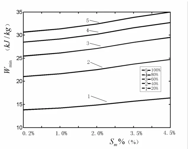
as the recovery ratio increases to 100%. When the salinity of incoming saline water are assigned various values of 0.2%, 1%, 2% and 4.5%, the minimum energy requirement changes with the similar laws, respectively.minimum energy requirement of the distillation system increases with the increase of the recovery ratio for the fixed salinity of incoming saline water. The minimum energy requirement per unit output pure water of endoreversible distillation system increases with the increase of the recovery ratio for the fixed salinity of incoming saline water. It can also be seen that the minimum energy requirement of the distillation system increases with the increase of the salinity of incoming saline water for the fixed recovery ratio.
Table 2 lists the distributions of the power inputs supplied to the endoreversible heat pumps and the power outputs produced by the endoreversible heat engines when the recovery ratio varies with given pure water output. The salinity of the incoming saline water is set to be 3.5%. It can be seen from the table that the minimum power input of the first endoreversible heat pump is a constant when the recovery ratio varies from 20% to 100%. The minimum power input of the second endoreversible heat pump, the maximum power outputs of the third and the fourth endoreversible heat engines increase with the increase of the recovery ratio. However, the maximum power outputs of the fifth endoreversible heat engine decreases with the increase of the recovery ratio. The same qualitative results can be obtained when the salinity of the incoming saline water takes the other values.
While for a reversible system, the minimum energy requirement is 2.248
kJ kg
/
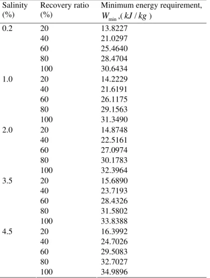
[6]. One can see that the results obtained herein are larger than those obtained based on reversible model.Table 1. Minimum energy requirement for incoming saline water with different salinities and recovery ratios
Salinity (%)
Recovery ratio (%)
Minimum energy requirement,
min
W
,(kJ kg
/
)20 13.8227 40 21.0297 60 25.4640 80 28.4704 0.2
100 30.6434 20 14.2229 40 21.6191 60 26.1175 80 29.1563 1.0
100 31.3490 20 14.8748 40 22.5161 60 27.0974 80 30.1783 2.0
100 32.3964 20 15.6890 40 23.7193 60 28.4326 80 31.5802 3.5
100 33.8388 20 16.3992 40 24.7026 60 29.5083 80 32.7027 4.5
Figure 2. The effect of salinity of the incoming saline water on the minimum energy requirement of given endoreversible distillation system
Table 2. The distributions of the power inputs supplied to the endoreversible heat pumps and the power outputs produced by the endoreversible heat engines
r
(%)P
1,min(kW )P
2,min (kW )P
3,max (kW )P
4,max (kW )P
5,max (kW )20% 8.9517 4216.6 1.4561 4092.7 4.8576
40% 8.9517 6490.4 2.2221 6202.2 2.7843
60% 8.9517 7908.3 2.6947 7488.4 1.5021
80% 8.9517 8877.0 3.0153 8354.4 0.6307
100% 8.9517 9580.6 3.2471 8977.2 0
5. Conclusion
A typical endoreversible desalination system model of sea water is established by using finite time thermodynamics in this paper based on Ref. [6]. The analytical expressions for the minimum power inputs of the first and second endoreversible heat pumps and the maximum power outputs for the third, fourth, and fifth endoreversible heat engines are derived. The minimum energy requirement of the endoreversible desalination system of sea water is optimized.
The minimum energy requirement characteristic for the endoreversible desalination system of sea water is similar to that of actual desalination system of sea water that minimum energy requirement increases with the increasing of the salinity of the incoming saline water and/or the increasing of the recovery ratio.
The results obtained herein are closer to those of practical system than those obtained based on reversible model. They can provide guidelines for design and operation of practical distillation system.
This paper performs the analysis and optimization based on the classical analysis and optimization performed by Cerci [6]. The major contribution of this paper is to show the application effect of finite time thermodynamics. The utilization of five heat engines and heat pumps was firstly provided by Cerci [6]. A further step based on it is made. Of course, nobody would use five expensive heat engines and heat pumps. Instead of the #1 heat pump and #3 and #5 heat engines, a counter current heat exchange of the flows would be much more efficient and cheaper to build, like the heat exchanger marked to and from
T
0 in Figure 1. A more realistic study than the one presented here would have been to compare a simple heat pump arrangement against such a pressure staged system. In this case, the finite time thermodynamic analysis and optimization can be also applied.Acknowledgments
This paper is supported by The National Natural Science Foundation of P. R. China (Project No. 10905093).
References
[1] Dodge B F. Thermodynamics of some desalting processes. Adv. Chemistry Ser, 1960, 27: 7-20. [2] Curran H M. Energy computations for saline water conversion by idealized freezing processes.
Adv. Chemistry Ser, 1960, 127: 56-74.
[3] Hawes R I, Leslie D C. A study of the mechanism of flashing flow by experiment and theoretical analysis. Desalination, 1967, 2: 329-336.
[4] Cengel Y A, Cerci Y, Wood B. Second law analysis of separation processes of mixtures. Proceedings of the ASME Advanced Energy Systems Division, 1999, 39: 537-543.
[5] Cerci Y, Cengel Y A, Wood B. The minimum separation work for desalination processes. Proceedings of the ASME Advanced Energy Systems Division, 1999, 39: 545-552.
[6] Cerci Y. The minimum work requirement for distillation processes. Exergy, An Int. J., 2002, 2(1): 15-23.
[7] Andresen B. Finite-Time Thermodynamics. Physics Laboratory II, University of Copenhagen, 1983.
[8] Bejan A. Entropy generation minimization: The new thermodynamics of finite-size devices and finite-time processes. J. Appl. Phys., 1996, 79(3): 1191-1215.
[9] Chen L, Sun F, Wu C. Finite time thermodynamics optimization or entropy generation minimization of energy systems. J. Non-Equilib. Thermodyn., 1999, 24(3): 327-359.
[10] Berry R S, Kazakov V A, Sieniutycz S, Szwast Z, Tsirlin A M. Thermodynamic optimization of finite-time processes. Chichester: John Wiley & Sons Ltd., 1999.
[11] Chen L, Sun F. Advances in Finite Time Thermodynamics: Analysis and Optimization. New York: Nova Science Publishers, 2004.
[12] Sieniutycz S. Thermodynamic limits on production or consumption of mechanical energy in practical and industry systems. Progress Energy & Combustion Science, 2003, 29(3): 193-246. [13]
Andresen B. Current trends in finite-time thermodynamics. Angewandte Chemie
International Edition, 2011, 50(12) : 2690-2704.
[14] Demirel Y. Thermodynamic analysis of separation systems. Separation Science and Technology, 2004, 39(16): 3897-3942.
[15] Shu L, Chen L, Sun F, Wu C. Thermodynamic optimization of distillation, separation, drying and reaction processes and devices: The state of the arts. Int. J. Energy, Environment and Economics, 2006, 12(4): 203-214.
[16] Nulton J D, Salamon P. Finite-time thermodynamic analysis of controlled heat integration. Proc. ECOS1998, 1998, 473-479.
[18] Tsirlin A M, Kazakov V A, and Zubov D V. Finite-time thermodynamics: Limiting possibilities of irreversible separation processes. J. Phys. Chem. A. 2002, 106(45): 10926-10936.
[19] Tsirlin A M, Romanova T S. Selection of the sequence of separation of ternary mixtures. Theoretical Foundations of Chemical Engineering, 2007, 41(1): 69–76.
[20] Tsirlin A M, Romanova T S, Grigorevskii I N. Optimal organization of binary distillation. Theoretical Foundations of Chemical Engineering, 2008, 42(4): 421-429.
[21] Tsirlin A M, Vyasileva E N, Romanova T S. Finding the thermodynamically optimal separation sequence for multicomponent mixtures and the optimum distribution of the heat- and mass-transfer surface areas. Theoretical Foundations of Chemical Engineering, 2009, 43( 3): 238-244.
[22] Tsirlin A M, Grigorevsky I N. Thermodynamical estimation of the limit potentialities of irreversible binary distillation. J. Non-Equilib. Thermodyn. , 2010, 35 (4): 213-233.
[23] Schaller M, Hoffmann K H, Rivero R, Andresen B, Salamon P. The influence of heat transfer irreversibilities on the optimal performance of diabatic distillation columns. J. Non-Equilib. Thermodyn., 2002, 27(3): 257-269.
[24] Shu L, Chen L, Sun F. Performance optimization of a diabatic distillation column by allocating sequential heat exchanger inventory. Appl. Energy, 2007, 84(9): 893-903.
[25] Ye D, Hu J. Databook for Thermodynamic Properties of Inorganic Substances (2nd ed.). Beijing: Metallurgical Industry Press, 2002 (in Chinese).
[26] Wu C, Chen L, Sun F. Optimization of steady flow heat pumps. Energy Conversion and Management, 1998, 39(5/6): 445-453.
[27] Ibrahim O M, Klein S A and Mitchell J W. Optimum heat power cycles for specified boundary conditions. Trans. ASME J. Engng. Gas Turbine Power, 1991, 113(4): 514-521.
[28] Wang S. Desalination Engineering for Seawater. Beijing: Chemical Industry Press, 2003 (in Chinese).
Liwei Shu received all his degrees (BS, 2000; MS, 2003, PhD, 2009) in power engineering and engineering thermophysics from the Naval University of Engineering, P R China. His work covers topics in finite time thermodynamics and technology support for propulsion plants. Dr Shu is the author or coauthor of 12 peer-refereed articles (six in English journals).
Lingen Chen received all his degrees (BS, 1983; MS, 1986, PhD, 1998) in power engineering and engineering thermophysics from the Naval University of Engineering, P R China. His work covers a diversity of topics in engineering thermodynamics, constructal theory, turbomachinery, reliability engineering, technology support for propulsion plants and optimization for iron and steel process. He had been the Director of the Department of Nuclear Energy Science and Engineering, the Superintendent of the Postgraduate School, and the President of the College of Naval Architecture and Power. Now, he is the Direct, Institute of Thermal Science and Power Engineering, the Director, Military Key Laboratory for Naval Ship Power Engineering, and the President of the College of Power Engineering, Naval University of Engineering, P R China. Professor Chen is the author or co-author of over 1430 peer-refereed articles (over 635 in English journals) and nine books (two in English). E-mail address: [email protected]; [email protected], Fax: 0086-27-83638709 Tel: 0086-27-83615046.