PUBLICAÇÃO DA ABCM • ASSOCIAÇÃO BRASILEIRA DE CIÊNCIAS MECÂNICAS
REVISTA BRASllBRA ()f CIÊNCIAS Ml'CÃNlCAS JOURNALOF THE BRAZil iAN SOCifTY OF MECHANICAL SCIENOE$
Vo!. I. N~ 1 (f97~)· Rioile Ja ne~o; i\sSQciação Brasileira de C ~nôlliS t;l ~ n íc~
Trime.stral lnelui re t e r ~ n c l a& bíbllonra!icas. 1. Mecanic.J ISSN ·0100·738G
A REVIS:lA B ~ ASILEffiA O[.ÇtENClAS MF-6Â ~ II6A$ p~bl!ca t t.~bathos que cobremos .,arcos ~s p eclos da
ciBnciae da tecnologia em Ell gen~arra Mecãmça,' lnctuíndo Interfaces com aslngenharlas Civil. Elélclca,
Ou1mica, Na•1al. Nuclear. AerouspatÍat. Alimentos. Açrlcota, PWôleo, M a ter i a l ~. etc .. bem tomo apfre<~ç~e~ · da F[i;jca e ~a Malemálica à Mecànlea
INDEXF.O bY A~p ll ed Mechanícs Ro v i~ w S' and Englneering lnfbrmalior.1: lnt ..
Pubhcaç!o daft'ublishad ~Y ASSOCIAÇÃO BRASILEIRA DE CIENCIAS M EC Â f'IIC~S TliE BRAZIUAN SOCifTY OF M EC fi ANiú~ L S C I~ NC ES
S ~ c r etar i:l da ABCM . Ana LúctafrOas de SOu<a llvenida·llia Branw. 1 2~ 18' Andar 20040·001 ijío de Janeiro RJ
Tet · (O~t) ~21-0 4 38/ r a x :· {Olfi 509-7128 . WW 'N . p~ c· r lo,br/ pa rceilast a bc m
abc•u@olornain.com.br
Pres\deme: Gartos .Atbertu ceAtmelda Ylce· Presidente: lians ln~ o Wetier .Setrulárlo: P a~ló B~ l ls1a Gonçalves Dlrotor de Patrirnôqiu: Felipe llasros d ~ F. tiach:id S!l(;relárlo Geral Nestor Alberto
z.
Perotra .Seêretãria 9\l RBCM: Mar(a de fâlima AIPnso 1ft Sousa \Jf.IICAMP - f(M • C P. 6122 1JOS3·970 tamp!nas SP
Te!: \0 19) 7Ba-3205/Fax: {019) 2&1·3n2 ,
f-Mall. ~or.m@~ m.u rnc a m p . b r
JOURNAL OF THE BRAZILIAN
~OCIHTY
OF MECHANICAL
~CIENCE~
REVI~TA
BRMILEIRA DE
CI~NCIA~
MECÂ NI CA~
EDITOR Leo,aroo Gcld,tein J•. UfUCAMP FEM Oflf ·C.P. 6122 13083-970 Camp'nas S•
Te I: (019) 289·3006ra>: (019) ?89 3722 EvMail abCITI~~crn.ur i i:?.l!lt!.bl
WITDRES ASSOCIA!lOS Ageoor de Tolertu Fleury IPT Instituto de t•esqu•sas Tecnolóqlcas
Dl•,isão de Mr:<:ânica c fiel! ridade ·/,gruJJ<1menrc de S slemas de Controle Cidade Uni•1crsWia c P 7141
O 1064 970 s.io Põulu SI'
lel.: (01 1) 268·2211 Rarr.ar 504 Fax: (01 11859 3353 E·Ma•L aglreury@lp1 br
Allsson Rotha Mach•rto Univcrsidaife Federal de Uber;iind1a
C~l)<lrtamenlo " ' tngenltaua Mecl ~ lca -Cam:us Santa Món·ca 38400.200 Ubertandia MG
Tet · (034) 239-4 149 ra.;: (034) 235;i382 E·Mail· allssonrr~ulu b•
t..rgela Ot..r 'lia t~ . ecke ' e
Ponlil'cia Unlvmidade Católica do R i ~ di Jarelro Dep;uta·nento de Enge11-harla Mectlnica Rua t.•arquês ~c São Vicente, 225 Gavea 22453·900 Rio d~ Ja1ciro RJ Tcl.: (021) ~J9 0719 fax: (021)29H t48 E-Ma!l· n:rx:kchf4inw.c.r>uc·•io.br thns lng!l Weber
Po11rffcla Unf,ersldadz Ca:ôlica do R o de Janeiru
Deí)artamemo de [ngenharia t ~J1el :; ! n ca
Rua Marou!s de s;o Vlce•rle. 225 Cávea 22<53·900 Rio de Jan•im HJ Tcl (021) 529 9323 ~ '"'' (021) 294-91•8 ( Mail hans@mf.c.puc·rlo.br P~uto Eigl Mlyagi
Unf·;ersldade de São Paulo tswla Polilêcrrca Oeparta.'llCOtO de fngeni •ria MeolmC!I • Mecalrônrca ~.venióa Prol. Mello Moraes. 2231
0550~ 900 $ão Paulo SP
lei.: (011) 81S·~oao F~x: (0 11}818 547 1/813·1886 E ·M ~ ~: pemryagi®aso.br
Seyyctl S~ i d Dana
Unlv·,sid>de Fed".1al da Pa•a ba
Cr.r,l!o de l etoó l ~ gi3-C ·3m pus I
Dep;ularnHIO de Tet110 I ~gia f.'e<:ánica
58059-900 João Pessoa PB fel. (033) 216-7356 Fax: (003) 216·7179 E·Mail: óana@dtm.et.l/lpb.b• COt\PD EOI fOR I ~ L · Alt ir de Faro Orlt1CO (PUG 11Ji Antonio Fraoc,sco f ortes (UnB) Am>ando Albertaw Jr.;UFSC) Atalr Rios Nero (Ut41VAP) 8cnr:<lito tloraes t>u•queilo (EESC·USPi Carlos Aberto de 111 nelda iPUC·RJ) Carlos >I be<to Martin (UFSC) Clovis Raimuudo Maliska (UFSC) Emanuel Rocha Vloiski (UNESP·f EIS) fmncisco Eml'lo Baccar ~ Nlgro UPT·SP) Francisco José Sioõ-:s (UFPb) Gencs•o José M•non (EfEt) llenriq"' Aozenleld (EESC USP) Ja r Carlos Oulra (UFSC) João Alma Hm de Jornada (UrRGSJ .lo•é João ae Espindola (UFSC) Jurandir lti1o Yanagiham (( P USPI llrio Schaeler (UF RG~)
Lourival Boehs (Uf~C) Luis Carlos Sar~o v ~l Goes (111\) Mareio Ziviani (UFMGJ tlafio Ussyr (EMBRACO) t ~o yses t ndeluk (COPPE·Uf RJ) t·I!SiOd' Ca<Ylllho Lobu 81001 (CDPP(·UfR.J) Nivaldo Lemos Copplnl (UNtCAMP) · I';'" lo Ato~so de Olrvua Sovicro (I tA) Rogêuo Manurs Sa'dznha da Gama (LNCC) Vaider St,llell Jr. (UFU)
REVISTA FINANCIADA COM RECURSOS DO
Programa de Apoio a Publicações Científicas
RBCM • J. o f the Braz. Soe. Mechanical Sclences ISSN 01 00-7386
Vol. XXI- No.1- 1999- pp. 1-9 Prlnted in Brazil
Tool Wear of Polycrystalline Cubic Boron
Nitride and Ceramic Materiais When Hard
Turning Bearing Steel
Alexandre Mendes Abrão
Universidade Federal de Minas Gerais Escola de Engenharia
Departamento de Engenharia Mecânica 31270·901 Belo Horizonte, MG Brazil abrao@vesper.demec.ufmg.br
David Keith Asplnwall
University of Birmingham
School of Manutacturing and Mechanical Engineering Edgbaston, Birmingham B152TT U. K.
Abstract
This work aims to invesligate the principal wear mechanisms involved when tuming AIS/ E53JOO bearinf( s/eel hardened to 60-62HRC using two grades ofpolycrystalline cubic bomn nitride (PCBN) and three grades ofceramic tool materiais (mixed alwnina, whisker reinforced alwnina and silicor~ nitride-bused). In addition to the tool l{fe data. scarming electronic micrographs of the culting edge and the projile of the rake and clearance faces are presenteei. The result.ç suggest that the mixed alrunina tool presented higfres/ flank wear resistance when cutting un.der finishing conditions. wherea.\' lhe low contem PCBN compact was superior wlten rough cuuing. DijJusiou, abrasion and plastic deformation were lhe 11WÍJ1 cau.,·e t~f'toolfailure. .
Keywords: Hem/ Tuming. Bearing Steel. PCBN and Ceramic Tools.
lntroduction
Thc advent of cubic boron nitride in lhe 70's and further developmcnts on oxide and non-oxide ceramic tool materiais allowed cutting of some difficull to machine materiais, particularly hardened
steels, hard cast irons and nickel-based alloys. However, due to differences in composition and
properties, the performance of these tool materials wiU obviously vary accord.ing to the cutting parameters and workpiece matetial. This papcr compares the performance of tive tool materiais when turning bearing steel hardened to 62 HRC with regard to tool life and wear resistance.
Gradual wear of advanced ceramic tool materiais when machining hardened steels is a complex process which involves several concurrent mechanisms. The relevance of each of these mechanisms to the tool life will vary according to the composition, and consequently the hardness, of the workpiece and tool malerials and lhe opcrating parameters being used. According to Hooper el ai. ( 1989) lhree
main processes are involved in the wear of polycrystalline cubic boron nitride (PCBN) cutting tools: chemical wear caused by interactions , with the environment (including aunospheric oxidation), the formation of a protective layer on the surface of the tool at high tempcrature and the removal of this layer by the swarf at lower cutting speeds (lower temperature) leading to altriLion wear and further chemical wear. When comparing the wear of a high content PCBN compact (Amborite) with a low content tool (DBC50) during finish cutting, Hooper and Brookes (1984) found that higher cutting temperatures were generated when using DBC50 dueto its lower thermal conductivity, leading to the formation of the protective layer on lhe rake face of lhe tool and consequently, lowcr wear rates than when using Amborite. Klimenko et al. (1992) also found signs of a liquid phase between the tool-workpiece and the tool-chip interfaces when turning bearing steel (60-62 HRC) using PCBN compacts. However, it was not clear bow the presence of this Jayer affected lhe wear behaviour of PCBN tool materials. Such layer was not observcd wben using alumina-based ceramic cutting tooJs. Other rcsearchers (Chen , 1993 and Xin, 1980) have identified the formation of this protective layer on PCBN tools.
Abrasion caused by hard particles present in the workpiece material, togethcr with dislodged tool material grains, are likcly to play a part. Wear of PCBN and both white and mixed alumina tools when turning cold work die steel (JIS SKDll, 60 HRC) is reported by Ohtani and Yokogawa (1988) as the result of abrasion caused by hard alloy carbide particlcs present in the workpiece.
Diffusion wear is probably of more significance, especially when considering the high temperatures that can be achieved at the tool-chip-workpiece interface. !t is believed tbal lhe prescnce of titanium
2 J . oi lhe Braz. Soe. Mechanical Sciences- Vol. 21. March 1999
carbide (Ti C) in the composition of the cutting tool can lead to lhe formation of the above mentioncd
protective layer on PCBN tools under a spccifi c range of cutting tempcratures and thatthis fLim can act
to prevcnt diffusion wcar. Although there is some evidence for sucb a laycr, it has not bccn explained
bow it can inbibit tool wear or wby it is not observed on A110 ,-TiC product~. Sucb tools possess lower
thermal conductivity than PCBN compacts conlaining TiC and thereforc are capablc of generating similar o r even bigber tcmperatures in Lhe cutting zone. Narutaki and Yamanc ( 1979) considered remotc Lhe possibility of di(fusion wear of PCBN tool s wbcn machining hardened stccls owing to the low affinity of Lhe CBN grain with iroo and to the lower tempcratures gencrated at tbe culling zone compared witb cememed carbide tool materiais.
Static diffusion tests between PCBN tools of diffcrent compositions anel DIN 100Cr6 bearing steel (60 HRC ) have indicated that recrystallisalion of the secondary phase occurs at bigh tcmperaturc leading to the weakcning of the binder material and hence contributing to the wear of lhe tool material
(Kõnig and Neises, 1993). In addition, subsequent abrasion lCSts carried out by tbe authors using a
diamond indcnter showed that tbe amount of wear increased with temperature rise, tbc wear scars on the low conccotration PCBN Lools being slightly deepcr than on the high concentralion products, although lhe weight loss caused by abrasion was nol signi ticant. Cutting tests, however, sbowed opposite results. One reason for lhis could bc lhe massive loss of CBN grains whcn Lhe bindcr phase surrounding the grain is eroded. The presence of TiC in lhe binder phase of DBC50 incrcased its etcbing resistance tbereby minimising chemical wear. Sliding tcsts using single CBN anel AI:O, grits against hardened
M-50
tOol steel (62 HRC) indicated that CBN grains presented approximately half of Lhe frictioncoefficient of lhe a lurnina, thcreby producing a more unifonn track and less ridgcs and rnicrocracks (Calabrese and Murray, 1989).
With rcgard to attrition wear, wclding of workpiece fragmcnts is reportcd to protect Lhe cutting
edge. however wben this material is rcmoved, particles o f lhe cutting tool may also be affecled. Takatsu
ct ai. ( 1983) reponcd Lhe welding of lhe workpiece material on lhe cutting edge after cutling differcnt lypes of hardcncd steels using cutting tools with various CBN conccntrations. The amount of wclding apparenlly increased with a decrease in thc CBN contcnt and protected Lhe cutting edge from wear. Work by Oishi and Nishida (1992) involving PCBN and severa! conventional ccramic lool materiais
when machining hardcned llS SUJ2 bearing steel (66 HRC) indicatcd thal under dry finisbing
conditions, there was a criticai cutting speed below which tool fracture did not take place. This criticai cutting speed was hi gher for thc PCBN than for a núxed alumina cutting tool. Surprisingly, the use of t:ulling fluid had a positivc cffect on thc tool life of tbc mixed alumina tool material. Similar results have bccn rcported whcn tuming hardcned low alloy steel (En2), where abovc 50 m/min cutting speed lhe zirconia toughened aJumina tool was ourperformcd by the PCBN, failing by chipping of tbe cutting edge (Nakai et ai., 1988).
Gane anel Stephcns ( 1983) reported tests involving turning o f hardened alloy steel En26 (550HV)
using Amboritc anel mixed alumina (A/103 + 20% TiC) cutting tools. At low cutting specds (50 mlmin)
lhe llank wcar of lhe PCBN tool was thrce times grcater tban that of tbe mixed alumjna, but wbcn Lhe cutting spccd was incrcased to 75 m/mi n rhe life of Lhe alumina tool was limited by cracking and cbipping of lhe cutting edge, wbercas lhe PCBN insert showcd relatively low wear. It was suggested that thc poor performance of tbe mixed alumina tool at the hi gher cutting spced was due lo its lower thcrmal conductivity anel inferior lhermal shock rcsistance.
When machining hardened cold work die stecl AISJ 02 using Amborile inscrts, it has becn reported by Nottcr and Heath (1988) that wear occurs almost immediately, afler which lhe cutting edgc stabilises and further wear takes place at a much reduced rate. Machining the same workpiece material with BZN-6000, Bhattacbaryya et al. (1978) assened that in general, a uniform flank wear occurred as a combination of bigh cutting speeds and relatively higb fecd rales. Tbe crater wear dcpth increased with an increase in lhe cutting spced. The cratcr width was dependent only on the feed rale (increasing the feed rate causcd a decrease in lhe crater width). Wben face milling hardcned steels using PCBN tool s,
tbe tool can also fail due to flaking/spalling anel tcaring of Lhe flank face anel also flaking of the rake
face as a consequencc of thermal fatigue in addition to lhe gradual wear mcchanisms, Xiangning anel Guangmin (1994).
Enomoto et al. ( 1988) suggcsl that tbe wcar o f PCBN tool when culling low aUoy steel (TIS SCM435H) of various bardnesses is caused by abrasion and adhcsion. Minimum flank wear was
obtained using cutting tools with 60% CBN contem and small CBN grain sizc (2 J.LID). It was s uggested
that reducing the grain si te increascd Lhe contact area between the CBN grains and Lhe bonding material
leading to a greater bonding force.
A. M. Abrão et ai.: Tool Wear of Polycrystalline Cubic ... 3
hardened Mccls with rnixed alumina ceramic tools, the formation of built-up edgc was reported by Vandcr Voort and Lesher (1994) to be dependent only on the hardness of the workpiece. Whcn thc bardness exccedcd a criticai value, lhe buih-up edge disappeared irrespective of thc cutting speed used.
Finally, plastic deformation leading to sudden fracture of thc cutting edge seems to affect mixcd alumina tools to a grcatcr extent lhan PCBN tools beca use o f the lower hot hardness o f lhe conventional ceramic material. As with cemented carbide tool materials, the occurrence of sliding wear, and consequently notching of tbe leading and truiling edgcs of ceramic tools, especially when machining hardcncd tool steels, is not well undcrstood and requires further investigation.
Experimental Procedure
Bars of AISI E52100 bearing steel approximatcly 150 mm in diameter and 750 mm long were used as workpiece material. The hardness of lhe workpicce was monitored with a portable hardness tcster
and it was found wilhin lhe range 60-62 HRC. Two grades of PCBN cuttiog tools (De Beers Amborite
and OBC50) wcre tested in additioo to convcnrional cerarnic tooling (Sandvik CC650-mixed alumina, CC670-whiskcr reinforced alumina and CC690-silicon nitride based cerarnic). The PCBN indexable inserts conformcd to SNGN 090316 and werc cmployed in a top clamp tool holdcr whicb provided lhe following geomctry: cutting edge angle Xr=45°, nonnal rakc angle y,:-6° and cutti ng edge inclination
anglc J..,=-7•. They incorporatcd a T-land chamfer of 0.2 mm x 20•. The ceramic tools conformed to
SNON 120416 and were similarly locatcd, but the normal rake anglc was
y,,
:-7• due to differencesbetween thc two toolholders used to accorrunodated different siz:e inserts. In this case lhe T-land chamfer was 0.25 mm x 20" for CC650 and CC690 and 0.1 mm x 20• for CC670.
Conlinuous dry turning tests were conducted on a high stiffness luming centre (30 kW, 3000rpm maximum rotational speed) equipped with a CNC unit. Tests were perfom1ed in accordancc to ISO 3685-1977 using lhe following cutting parameters: culting spccds (vc) of 70, 140 and 200 m/min, feed
rales (f) of 0.06 and 0.25 mm/rev and depths of cul (a, ) of 0.5 and 2.0 rum. A full factorial experiment
was dcsigoed resulting in 12 cutting conditions for each tool material.
lnitially, a toollife criterion bru;ed on a avcrage flank wear VB=0.3 mm was cstablished. However,
tests were slopped aftcr 30 minutes i f lhis va luc had not been reached. In severa.! instances Lhis was thc
case and thereforc Lhe v-T result.~ are presenled using VB:0.2 mm to avoid the use o f exlrapolated data.
flank wear was measurcd using a toolmaker's microscope cquipped with digital micrometers. Workpiccc surface roughness was monitored using a Milutoyo Surftest 201 unit sct with a 0.8 mm cut-offlength.
The proftle of the rake and 11ank face wcrc obtained with a Talysurf 5 system after etching sample culting tools in a 50% HCl solution. Pholographs of worn cutting tools were taken using a scanning
electron microscopc and due to differences in lhe clcctrical conductivity of the tool materiais used, all
inscrts were gold coated beforc examination.
Results
Toollife curves obtained from the flank wear data for a depth of cut of 0.5 rum and feed rale of 0.06
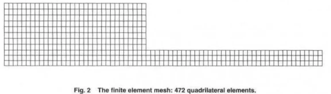
mm/rev are shown in Fig. 1, whereas Fig. 2 shows the results wben feed rate was increased to 0.25
mm/rev. The rnixcd alumina tool (CC650) providcd bcst results ata feed rate o f 0.06 mm/rev. but failed
wben both feed rale and cutting speed were incrcascd, whereas the low contenl PCBN tool (DBC50) gave good resulls undcr both 0.06 and 0.25 mm/rev. At the lower feed rale CC670 produced a negative slope much steeper than the rest of thc toolmaterials, however, withoullhe loollifc values at 70 m/min for OBC50, CC650 and CC670 (wbich did not reach the tool life crilerion, and thcrefore, are not presentcd) it is difficult to establisb prcciscly thc tendencies for these lool materiais.
The whiskcr rcinforced alumina (CC670) also failcd suddenly wben cutting speed increased to 200 m/min. Oue to its high hardness and toughoess. the high conlent PCBN tool (Amborite) was expected to
perform better at higb feed rates, but this was not the ca~e. Finally, the silicon nitride-based cutting tool
presented lhe worst results for all cutting conditions.
Figures 3 and 4 show lhe v-T curves obtained for feed rates of 0.06 and 0.25 mm/rcv, respectively.
and a depth of cut of 2.0 rum. In general, it can bc seen that for a feed rate of 0.06mm/rev lhe same
trend observcd previously was maintained, where CC650 gave longer tool life, however, a sligbt
reduclion in tool lifc was reported in comparison to iip=Ü.5 mm. Additionally, only CC670 and CC690
4
~
c: 'é
~
g
f-J . of the Braz. Soe. Mechanical Sc1ences-V oi. 21 , March 1999
I()() ...- - ---"T --.-- -.- .- ,.- ,---~ -- -.- ----. -,
1
-+-Amld.el
lO
lO 100
Cutting spccd (m/min)
-e-DBC50
....-cc6so
-&-CC670 ..._ CC690
1llfi1
1000
Fig. 1 v-T curves for hardened bearing steel at f=0.06 mmlrev and ap=O.S mm.
~
-~
5 I()
~
-~
0.1
l O 100
Cutting speed (mim in)
-+-Amb<>n"'
-e-oscso
I
ó. CC650
I
-e-cc1;7o -+- ccó90I ~
~ ·
1000
Flg. 2 v-T curves for hardened bearlng steel at f=0.25 mmlrev anda ap=O.S mm.
lO 100 1000
Cullm& <p«d {mlllW'I)
Fig. 3 v-T curves for hardened bearing steel using a 1=0.06 mmlrev and a.,=2.0 mm.
A further diminishing in tool life was noticed when t11c feed rate incrcased to 0.25 nuu/rev. Undcr
this circumstancc lhe mixcd alumina material could not withstand cutting even at lhe lowest culling
speed. For thc m o~ t severc opcrating conditio n Amborite provided lhe best result, lasting Iess than one
A M. Abrão et ai.. Tool Woar of Polycrystalllne Cubic ...
H'
I
~I
;
.,:
U,l
'I
I100 Cu nm ~ "JlCCd 1 ruluun 1
- A ...
~r1
-=1- lm(.'~()
6 t.t.'tt.~l -n ' 6~t _. CC~
HKXI
Fig. 4 v-T curves for hardened bearlng steel uslng a f=0.25 mm/rev and a.=2.0 mm.
5
Figure 5 shows samples of tool wear generatcd after reaching the tool life criterion under various
cutting conditlons for those material~ which presented superior performance. i.e., CC650, DBC50 and
Amborite.
When rinish turning with CC650 an increase Íll cutting speed from 70 to 200 m/min (Fig. 5a and 5b,
respcctively) led to chipping of lhe eulling edge and accelerated tlank and crater wear. Rough tuming parameters caused the fracture of the culling edge. The same trend was observed whcn culling with
DBC50 tools (Figs. Se and 5d). When cutting with Amborite (Figs. 5e and 51) thc tool wear appeared lo
be more severe when finishing than whcn roughing. Increasing lhe cutting speed and feed rale led to the
appearancc of grooves on lhe cratcr surfaee near the rake face. The discontinuous tüm shown in Fig. 5f
was dueto poor adhesion o f the gold coating applied prior to lhe SEM analysis.
The profile of the clearance and rake faces after reacbing the tool lifc criterion whcn fmishing and
rougbing can be 1>een in Figs. 6 and 7 , respectivcly, where lhe cutting limeis shown betwecn bracketl>.
a) mm b)CC650
mm
e) Amborite v.=200 m/mln, f=0.06 mm/rev end a0=0.5 mm f) Amborite v.=200 f=0.25 mm/rev a
6
a) Amborite (4 mín)
c) CC650 (26 mln)
e) CC690 (2 mln)
J. of the Braz. Soe. Mechanical Sciences • Vol. 21, March 1999
b) DBC50 (16 mln)
d) CC670 (2 mín)
Scalc:
H
0.2mm
I
0.05mmFíg. 6 Profíle of lhe rake and tlank faces after finlsh turning (vc=.200 m/min, f::0.06 mmlrev and a.,:0.5 mm) hardened AISI E52100 steel wlth: a) Amborlte, b) DBC50, c) CC650, d) CC670 and CC690.
When finish 1urning , CC650 showed the bcsl crater wcar resistance followcd by DBC50 and
Amborite. CC670 showed a rapid loss of the cutting edge and excessive wear was observe<! on CC690. When rough turning Amboritc gave the bcst resuh. Both CC670 and CC690 presentcd insuflicient crater wear resistance and thc profile of DBC50 and CC650 tools afler roughing are not shown due to tool fracture.
a) Amborite {8 mln)
c) CC690 (2 mln)
b) CC670 (4 mln)
Sale:
H
0.2mm
I
0.05mmA. M. Abrão et ai.: Tool Wear oi Potycrystalhne Cublc ... 7
Discussion
Whcn cuning wi lh a dcpth o f cut o f 0.5 rum and a fccd rate of 0.()6 mm/rev (Fig. I ), CC650 and
DBC50 gave comparable results, followed by CC670 (at lower cutti ng speeds). Amborite tool life was shorter and CC690 shortest of ali. When thc fced rate was increased to 0.25 nunlrev, howcver, lhe tool life of thc m.ixed alumina cutting tool showcd a draslic rcduction ending in catastrophic failure. The v-T curves for f=0.25 mm/rev (Fig. 2) shows that DBC50 provided the bcst flank wear resistance, followed
by Amborite in~tcad of CC650. Th.is is an indication lhat when machining materiais within this levei of
hardness, lhe mechanical propcrties of the tool, particularly hot hardness and fracrure toughness, are crucial for a satisfactory performance. The fracturc toughness of Amborite is approxirnately tive times highcr than reported values for CC650.
When the deplh of cut was inereascd to 2.0 mm (Fig. 3) the samc trend observed previously was
maintained. however, as the cutting spccd increased, the flank wear rate increased considerably, even so
CC650 exhibited su perior tool wear resistance. Neverthelcss, wilh an incrcase in feed rate to 0.25 IDJnlrev none of lhe tool materiais was able to produce a satisfactory performance. DBC50 gave lhe
longest toollife resu lts at 70 and 140 m/min but was outperfonned by Amborite at 200 m/min. lt would
appcar that when rough turning at cutting spccds as high as 200m/min, the mcchanical and thermal stre:.ses irnposed are too high for most of the tool materials. Failure occurred within a short period of time eilher due to lack of toughness or as a consequence of accentuatcd diffu sion wear caused by the high tempera111res generated at lhe tooVclúp interface. Tbc overall poor performance of Amborite compared to DBC50 when rough cutting was a surprise since the former product is partieularly
recorumended for hcavy/rough cutting operations. In spite of its high hot hardness, the inferior wear
resistance of Amborite eould bc explained in terms of grain siz.c. According to Enomoto (1988).
reducing the C BN grain size the contact arca betwcen the C BN crystals and lhe binder phase is
increased leading to a grcater bonding force. This would bc an advantage in favour of DBC50 whose
grain size is approximately one tenth of lh<tt o f Amborite. Furthermore, lhe presence o f titruúum carbide
increased lhe wear resistance of DBC50 due to its lower solubility in stecl compareci to CBN (Kramer,
1987) and also bccause of i L ~> good atmospheric ctching resistance (Hooper el ai., 1989).
The micrographs of wom cutting tools (Fig. 5} together wilh lhe profile of lhe rake and clearance faces after finish and rough tuming (Figs. 6 and 7) give ao insight into the possible wear mechanisms acting when machining such high hardncss workpiece materiais. Whcn fuúsh tuming with Amborite, the smooth appearanee of lhe crater was onc possible indicatioo that di ffusioo had occurrcd and lhe grooves oo thc clearance face suggested that abrasioo was also a factor. Since thcse grooves wcre notas
distinctive wbcn usiog lhe olhcr tool materials, it would scem logical to assume that lhey were not
caused by hard carbide particlcs present in Lhe workpiece, but by loose CBN grains which rubbed against the clearancc face. They werc also noticed, to a much lesscr cxteot, when tuming at v"=l40 m/min, f=0.25 mm/rev and a,.=0.5 mm but were noL observed wilh DBC50 tools. Therefore their appearance was associated with a combination of high cutting speed and feed rate. Tbey could be a
result of chenúcal wear when high temperalurcs are reached in the tool/ehip interface, which did not
occur with DBC50 because of lhe presence o f titanium carbide and the lower thermal conductivity of
lhe low CBN content product. Tbis form of localised wear may al so bc associated with the
manufacturing routc of the compact. It has been reported by ll ooper et al. ( 1989) lhat during the synthesis of lhe tool blank.s, the CBN grains in DBC50 are subjected to much less plastic dcformation than in Amborite. As a result, DBCSO will possess higher resistance to wear caused by the devclopment of structural defects in lhe C BN grains.
Similar wear pattems were observed in DBC50 and CC650. When rurning al v<=70 m/min, f=0.06
mm/rcv and <~v=0.5 rum minimal wear was observed after 30 minutcs, but when thc cuning speed was
increased to 200 m/min signs of chipping of the cutting edge were evideot. The texl11re of Lhe crater
produccd in CC650, particularly in Fig. 5a. and of lhe crater and rake faces of DBC50 (Fig. Sd) indicated lhe occurrence of diffusion wcar. Tbe profile of the cutting edge when finish turning
suggested that lhe mixed alumina product had a higher eraLer wear resistance tban DBC50. ln contrasr,
thc gross fracture observed when rough tuming using both materiais indicatcd insufficient fraciUre
toughness (k,,=3.7 MPa.mM for DBC50 and typically k1c=2.9 MPam''' for AJ,O, + 30% TiC according
to De Becrs, 1990}. Certa.inly. this difference accountcd for the fact lhat the CC650 fa.ilcd after 30 seconds of cutting whereas the DBC50 laSted for 4 minutcs.
8 J. of lhe Braz. Soe. Mechaníca1 Sciences-Vol. 21. March 1999
CC670. The wear of lhe silicon nüride-based product when finishing was characterised by spalling and fracturc, possibly caused by lhe weakening of lhe culling edgc due to rbc high di ffusion wear ratcs evident from rapid crarering.
Conclusions
When continuous tuming hardened bearing steel using PCBN and ceramic cutting tools, the following conclusions can be drawu:
• Superior wear resistance was obtained by the mixed alurnina tool and by tbe low coutcnt
PCBN at low feed rate (f=<l.06 mm/rev);
• Wbcn lhe feed rate was incrcased to 0.25 mm/rev, lhe low and high contcnt PCBN compacts
gave bcst results, in this order;
• Tool wcar mi crograph~ and prolile samples suggest lhat diffusion and abrasion (causcd by
dislodgcd CBN grains) wcrc the principal reasons for tool wcar of thc high contcnt PCBN compact. whereas thc low contcnt compacl and tbe mixed alumina tool failcd due to diffusion
al low fecd rates and plastic deformation followed by catastropbic failure at lligb feed rates.
References
Bhattacharyya. S.K .. A~pinwall. D.K. and Nicol. A.W .. 1978, 'Thc application of palycrystalline compacts for ferrous machining". Proceedings. 19 .. lntemauonal Machinc Tool Oesign and Reo,earch Conferencc, Manchester, UK, pp. 425-434.
Calabre~c.S.J. and Murray.S.F .. IYllY. "SEM ohscrvation~ of the sliding bchavior of Ab03 and CBN against ~ t eci",
Scanning. Vol. 11(5). pp. 231-236.
Chen.W .. 1993. "The rnachining of hardened Meels using ~uperhard CBN tooling and CBN tipped rotary cutting tools". PhD Thcsis, University of Birmingham, UK.
De Beers Industrial Diamond Divis ion. 1 Y90, "DBC50", Technical catalogue n•. I 14000890.
Enomoto, S .. Katt),M. and Miyv.awa.S .. 198!!. "Flank wear of CBN cutting tools o f various cnmpositions" . .lournal of Mechanical Working Technology. Vol. 17. pp. 177- 186.
Gane. N. and Stephens. L.W .. 1983. "The wear and fracture resistance of cerarnic cutting tool~ ... Wear, Vol. 88. pp. 67 - 83.
Hooper. R.M .. Shakih,J.l.. Parry ,A. and Brookes,C.A .. 1989, "Mechanical properties, rnicrostructure and wear of DBC50 ... Industrial Diarnond Review. Vol. 4. pp. 170 - 173. Hoopcr.R .M . and Brookes,C.A., 1984. ''Microstructure and wear of cubic boron nitride aggregate toob". Proceeding,. 2d tntemational Conference Scicnce Hard Materiais, Rhodes. pp. 907 - 9 17. 1503685, 1977. "Specilication for tool lifc testing with single pointturning t.ools''.lnternational Standartl~ Organization.
Klimcnko.S.A .. Mukovoz.Y.A .• Lyashko,V.A .. Vashchcnko.A.N . and Ogorodnik, V.V .. 14;192. ·'On the wear rnechanism of cubic boron nitride ba.~c cuuing tools ... Wear. V oi. 157. pp. I- 7.
Kõnig,W. and Nei~es.J\ .. 1993, "Wear mechanisms of ultrahard, non-mctallic cutting materiais". Wcar, VQI. 162-164. pp. 12-2 1.
Kramer. B.M., 1987. "On tool materiais for high spccd machining". Journal of Enginecring for lndustt)' (Transactions of lhe ASME). V oi. 109. pp. 87-91.
Nakai,T .. Goto.Y. and Nakatani.S .. L988, "Cuttiog perfommnce of PCBN and PCD for P/M parts", Proceedings. Modern Devclopments in Powder Merallurgy. V oi. 19, Orhmdo. USA, pp. 379 393.
Narutaki. N. and Yamane. Y., 1979. "Tool wear and cuuing temperature of CBN tools in machining of hardene~ Mecls". Annals of the CIRP, VoL 28(1). pp. 23- 28.
Notter. A. T. and lleath, P. J.. 1980. "Machining of hard ferrous materiais with Amborite". De Becrs Industrial Diarnond Division, Technical Service Centre. Chaners. Ascot. England, pp. 6- 13.
Ohtani, T .• and Yokogawa,H., 1988, 'The cffects of workpiece hardness on tool wear charactcl'istics/Machiniog of cold work tool steel with CBN. ceramic and earbide U)ols", .Bulletin of Japan Socicty of Precision Engineering, Vo1.22(3). pp. 229-23 L
Oishi.K. and Nishida,T., 1992, "Study oo the fracrure charncteristics of ceramic cutting toob - first repart". Wear. Vol. 154, pp. 361 - 370.
A. M. Abrão et ai.: Tool Wear of Polycrystalline Cubic ... 9 Vander Voort. G. and Le ~ her.J.A .. 1994, "Prcparmion of high alloy martensitic steels". Struers Journ;tl of
Mctalography , Vol. l, pp. 3-8.
Xiangning.W. and Guaogmin.L., 1994. "'Study on the tool wear of PCBN face milling cuner", Procccdings, Advancement of Jntclligent Production. The Japan Socicty for Precbioo Engineering. pp. 401 -406.
RBCM -J. of the Braz. Soe. Mechanlcal Sciences
Vol. XXI- No. 1 • 1999 • pp. 10-16
ISSN 0100-7386 Printed in Brazil
Analysis of Polyethylenes Used to Coat
Telephone Wires and Cables Submitted to
Severe Wether-Ometer Conditions
Derval dos Santos Rosa José Eduardo Volponi Sebastião Sahão Júnior CPqD-Fundação
Rodovia Campinas Mogi·Mirim, Km 118.5 Camp1nas. SP Braz11
derval@cpqd.com.br Abstract
l'olvethylene.\, usecl to coat teleplwne cabln anel "ires, are the nwleria/.1 1/wt lwl'e s/UJ\1'11 the be.vl behm•ior ll'hen .111bmined to the acrion uftlw em·iromnent; in many cti.Ie.• they last m·er '" enty .vears. Amnng them, ,..e highlightlou·-clemity polw•thylene (WPE). tluu. however, Jw.1 /ou re.1·i.vtance to abrasion: thi.\ muJ.es impossible it.\' use in lif'/1\'0rÁ.!. that um/erga a gretll incidem·e of /..ires and culling materiais. An allemotil•e for this muteriul is tlll! high-deiiSity po/yethylel/e ( IJDPE). Dewi/ed studies hm·e .1 /11111'11 thm both. in lhe labomtrny 11.1 in the .field. hal'e sim i lu r l>eiw1•wr as 10 resrstance to severe wemher ('{mditirms. with The adtlitional advantuge tlwt 1/D/'F, hus u nwclt higher mechanical re,,·ivtunce. This work pre.\'l!tUS 1m asst's,,.,,,em of lhe belwvior of these materiais and demonstra/i' wlty
they have an e.lcellenl resistam·e to ,\'t'l'ere wemher mmlitions. 1\.eywords: \Vire and Cahle CIHI/tnf:, Pohethylmes. Agmg
lntroduction
The presence of polymeric materiais in the lelephone network has been increasing along the years due to the high costlbenefit ratio these materiais deliver to telecommunications products: low costs, good mcchanical properties. high performance and long life. provided they are used adequately. Among tbose most used, one can mention polyethylenes, wbich can be: Higb-Densi ty Polyethylene (HDPE). Low-Density Polyethylene (LDPE), Low Linear Density Polyethylenc (LLDPE), etc.
These polymeric materiais are rated as "commodities" anel are widely used in coating of telephone
cables anel wires, with some applications also in Optical Splicc Closures, Sub-Ducts, lnsulation of
Telephone Cable Coneluctors. etc, anel have exccllent performance, when submitted lo severc weather conditions: heat, raio, polluunts aod, abovc ali, UV radiation from the sunlight. Althougb thcy belong to thc same family of materiais, polyethylcnes have significant differences in their propertics due to
minor differenccs in their structurcs. Figures l(a), l(b) and I (c), bclow, illustrate Lhe structures o f
Higb-Density, Low-Dcnsity anel Low Linear Density Polyethylenes:
---(a)
I
(b)
I I
II I
(c)
Flg. 1 Schema of the molecular structure of: (a)-LDPE; (b) • HDPE and (c)-LLDPE
D. S. Rosa et ai.: Analysls oi Polyethylenes Used to Coat Telephone Wlres ... 11
These struclure clifferences determine different physical and mechanical properties, and have a direct inOuence on thc bchavior of these materiais in telecommunication products, mainly with respect to dimensional stability and resistancc to abrasion, and, at times, resistance to being c ut.
LDPE's low cutting and abrasion resistances have beco observed in telephone wires installed in
arcas with great incidence o f kitcs preparcd with cutting strings, as illustrated in Figs. 2 and 3.
Fig. 2 Telephone wlres and cables involved with kite strings.
Flg. 3 Detail of a cut in a telephone wlre
Nevertheless. LDPE has been used in shcath of wires and cablcs. and has shown an cxccllent bebavior and performance in sevcrc weather conditions. Currently there are reports of cables that have been installed for over 20 years in thc Brazilian Telecommunication Company telcphone network, with
12 J. of the Braz. Soe. Mechanical Sciences- Vol. 21 , March 1999
As HDPE has a more uniform molecular structure, that is, more crystalline, its rcsi~lance to cuLS or
abrasion is higber than LDPE, and this feature is even more evident in Lhe prcseoce o f heat. because the
LDPE hardening and softening points are very low. Our studies, have shown that HDPE has thc same behavior as LDPE when submítled to scvere weathcr conditions. both in laboratory and in the field, and these resulLS will bc presented ncxl.
Materiais and Methodology
Thc materiais used in dcvcloping this work werc:
• Purc LDPE:
• PureHDPE;
• LDPE with 2.5% carbon black, plus chemical stabilizcrs, and
• HDPE with 2.5% carbon black plus chemical stabilizers.
where
• Low-Density Polyethylene:
Density: 0.92-0.94 g/cm~
Melt Flow lndex: 0.6 gJ 1 Omin.
• High-Density Polyclhylene:
Density: 0,95-0,97 g/em'
Melt Flow Index : 0.8 g/lOmin.
• Carbon Blaek N 220
From these fonnulations, standard specimens were prepared for tensile strength tcsls. They werc submitted to naluraJ and aecelerated aging tests, so lhat thcir meehanieal propertics eould be assessed before and after agiog.
Thc purpose of lhe addition of earbon blaek and chemieal stabilizers to polyethylenc was to ioerease stability of lhe material lo severc wealher eooditions, particularly to ultraviolet radiation from sunlighl, and hcat. Carbon blaek is an absorber of ultraviolet rays and, in order to detiver an effective
protection to the polymer, its grain size should be smaller lhan 25l1fl1 (N220 carbon black ) and the
concentration should bc 2 lO 3 percent of the polyrneric matrix mass. Above 3%, no significant protection improvcment was noticed, doe to lhe difficulty of incorporating and dispcrsing carbon black particlcs in Lhe polymer matrix.
Aging
To study lhe bebavior o f the polyelhylenes when submiued lo severe weather conditions, two lypes of aging procedurcs were used: natural aging in resl fields and accelerated aging in laboratory.
Thc acceleratcd aging test is usually conducted on an apparatus named "Weather-Ometer ®", which
supplies weather conditions as close as possible to those found in nature. It simulates sunlight radiation
with a xenon are lamp; it also simulates lemperalUrc, humidity and rain. The tese parameters uscd were thc following, in aecordance with ASTM G-26:
• Xcnon are lamp 6500 W with borosilicate filters
• Two-hours cycles (I 02 minutes of light + 18 minutes of ligbl and watcr spray)
• Black pancltemperature
=
63±
5 °C• Relative humidity = 65 ± 5%
• Radiation at 340 nm = 0.35 W/m2
In the natural aging test, samplcs were exposed directly to the samc conditions of product use, but the responsc time was very long. ln this work, materiais were installcd in differcnt locations of the
country, including climates that are very aggressivc to polymers. The thrce cities chosen were:
Campinas- SP. Fortaleza- CE and Belém- PA.
Laboratory Tests
O. S. Rosa et ai.: Analys1s of Polyethylenes Used to Coai Telephone Wires ... 13
In general, when polymers are submiltcd to degradation. they tend tn reduce their tensile strength
and their res istance to abrasion and bccome more briulc; therefore they rcduce their elongalion at break.
Tcnsile strength and clongation at break are parameters measured in standard tcst specimens, in
accordance to the ASTM D-638 norm. To measure resistance to culling, there is a specific tcst which simulatcs a real situation. where a standard "cerol"(kite string with little fragments of glass and glue) cutting küe string is placcd in contact wilh lhe telephone wire, and the number of cyclcs required to cut
the string is measured wilh a frequency of 1 .5 Hz. A schcmatic drawing o f thc test assembly is shown in
Fig. 4.
Telephone wire (transversal)
"Cerol"outting string
---M =400g
Fig. 4 Resistance to cuttlng test assembly
In addltion to the prcviously described tests to foltow degradati on, anolher widely used test lO assess lhe performance of polyethylenes, before aging. is the measurement of lhe coefficient of carbon black absorption in ultraviolet. The purpose of this spectroscopic tcchnique is to evaluatc lhe degree o f
dispersion of carbon black particlcs in the polyrneric matrix, since lhis property is direclly linkcd to lhe
stability o f the material to wealher, particulady to ultra violei radiation.
Another lechniquc to eva luale carbon black dispersion ls optical mi croscopy, where onc can check
qualitarively i f lhe carbon black particlcs are well di sperscd in the polymeri c mau·ix.
Results and Díscussíon
lnitiabl y the carbon black (C. B.) formulation was characterií'.ed by measuring its absorption cocfficiem in the ultraviolet:
LDPE 2.5% carbon black ~ 3607
:t
64 abs/cmHDPE 2.5% carbon black ~ 4084
:t
110 abs/cmand dispersion by optical microscopy. These results are shown in Fig. 5.
LDPE HDPE
Flg. 5 Micrographles showing carbon black dlspersion in LDPE and HDPE.
The analysis of these results. showcd that bolh fonnulations with carbon black had good dispcrsion (lhcrc are no parliclc clusters - Fig. 5). Also, they have a high absorption coefficient in lhe ultraviolct, above 3,500 abslcm. Thcrcfore, both fonnulaúons have good stability against severe wcather conditions
14 J . of the Braz. Soe. Mechanical Sciences- Vol. 21 . March 1999
Thc mechanical properties after acccleratcd aging in lhe Weather-Omctcr are shown in Figs. 6 and 7. where small differcnce bctween pure polyethylene and with addition of carbon black can be obscrwed. Bcfore 1,000 hours of uging the same bchavior wus maintained, howevcr. aftcr that, one can see a sharp decrcase in the mechanical propcnies of the pure material. As to lhe p<1lymers with add iti ve, both preserved their mechanical propcrties up to lhe end of the test, i.e., approximately 3,500 bours. N01e that the values for thc HDPE tensilc strength are greater than for LDPE.
In thc case of natural aging, despite thc short time exposurc (two years), Figs. 8, 9 and 10 show that
no differcnces were found among polyetJ1ylencs as to their tensilc strength during thc period a~:lyz:ed.
ACCELERATED AGING IN THE WEATHER-OMETER
.-~
60.lo: cu 50
Q)
.... 40
ID iQ 30 c
.2 20
iQ
-+--
LDPE pure -tt-LDPE 2,5% C.B. __..,_ HDPE pure,.._ HDPE 2,5% C.B.
Cl 10
c
o
üi
o
o
1000 2000 3000 4000Aglng Time ( hours )
Fig. 6 Results of lhe elongation at break after aging in the Wealher-Omeler
ACCELERATED AGING IN THE W EATHER-OMETER
350 300
I ~L DPEpure
, _ _ LDPE 2 ,5% C.B.
I
--..- HDPE pu r e
I
1-
HOPE 2,5% C.B..s:.
Õl 250
c~
QIN
:; E
200
(/)~
.!!!ÕI
·- .;,t
150
V I
-c
~
100 50
o
o
1000 2000 3000 4000Aging Time ( hours)
o. S. Rosa et ai.. Analysis of Polyelhylenes Used to Coat Telephone Wires ...
~ 350
-
Cl 300iN'
2so!:
E
200(/) <J
~ ~ 150
·- .:tt:. 100
"'
-c
504)
...
o350
~
300
-
Clc:
-
2504) C'll
...
E 200-(/) <J ;;:: 150
.!!
C) Ui-
.:tt:. 100c: 50 4)
...
o
350 ~ 300...
Clc: - 250
Q)C'II
... E
200c;;~
.!!Õl 150
·-U I -.:tt:. 100
c: 50
4)
...
o
o
NATURAL AGING IN BELÉM
··· li: ···· ····
-2 3 4
Aging Time (years)
l
HDPE 2,5% C.B. l• • • • • • LDPE 2,5% C.B.
Flg. 8 Ten slle strength after natural aging in Belém
NATURAL AGING IN FORTALEZA
. - - - -
- - -
-·---o
o
·:E ...••••• . x:
2 3
Aging Time (years)
4
1-
HDPE2,5% C.B.l· . · . · -·
LDPE 2,5% C.B .Flg. 9 Tenslle strength after natural aging in Fortaleza
NATURAL AGING IN CAMPINAS
-... . x -... z: ... ~ . . ·
-2 3 4
Aging Time (years)
- - HDPE 2,5% C.B. I
· · · - · LDPE 2,5% C.B.
Flg. 10 Tenslle strength after natural aging in Campinas
16 J . of lhe Braz. Soe. Mechanlcal Sciences- V oi. 21 . Ma rch 1999
Thc resistancc to c uuing tcsts, conductcd on telcphone wi rcs with Lhe same configuration, but wilh diffcrcnt coating materiais gavc:
Wirc coaled with LDPE: 34±2 cycles
Wirc coated witb HDPE: 125:1:7 cydes
Whic h shows that HDPE's rcsistance lo culting with cerol string was much higher lhan LDPE's.
Conclusions
Afte r up to 3,500 hours aging in lhe Weather-Ometcr, and aftcr two years of natural aging in tbrcc test fields, thc analysis of the mechanical propcrties showcd that HDPE and LDPE have tbc same performance undcr severe wcalher condiüons. HDPE also has greater rcsistance to cutting and abrasion,
a criticai propcrty for which tbc sheathing o f lelephonc wires anel cables is applied.
Acknowledgement
Thc authors thank T ELEPARÁ anel TELECEARÁ for the installation of Lhe tcst specin1cns in tbeir test ficlds.
Reference.s
Allen. ~.S .. 1983 . .. Dcgradation and Stabil i1ation of Polyolefins", Applied Science Publishers. F.10sex. p.384. Amcric;m Sociery for Tesling and .Ylaterial ~. 1995. ASTM G-26/95 - Standard Practice for Opcrating Light Exposure
Apparatus (Xenon 1\rc Type) witb and without wmer for Exposure
or
Nonmetallic Materiais, p.l O.American Society for Testing nnd Materiais, 1996. ASTM D-638/96 - St;mdard Tcst Methnd fo r Tensilc Properti es of Pla~Lics. p.l3.
Ragarolli. A .. Silva . .Yt.C. and Lopes. S.J.C. 1995. Technica.l Report PD.I 2.AT.CST.OOOSA/RT-01-AA: CPqD TELEBRÁS. p.52 (internai communi cmive).
Brydson, J.A .. 1975. " Pia.stics Matcrials", Ncwncs Butherwortbs, p. 182-2 16.
Davis. A. and Davis, S., 1986. "Weathering of Polymer". Applied Scicncc Publi,hcrs L1d., I cd. New York, 289p. Gilmy. H.M. and Chan. M.G .. 1984, ~ Pol ymer Scicoce and Techoology ... v.26 . p. 2D-287.
Gugumu~. F .. IY!!9. Polymer Dcgradation nnd Stabüity, v.24 . p.289-301. Uugumus, F., 1Y93, Polymcr DcgradaLion and Stability, v.39, p.ll?- 135.
Ognrkiewicz. R.M .. 1974 ... Thermoplaslics - Propcrties and Dcsign", John Wiley & Sons, New York, p. 155- 160. Parris. D.R. and Gao. Z .. 1997. "lntemational Wire & Cable Symposium Procecdings··. p.l22-125.
Sahão Junior. S .. 1996. Report of Rcsearch Projcct Applicated in Special P olymer~- Tclcbrá'- S/ A P .A. PER PD .33.PE.004.C>OO!NRT-04-AA. p.29 (internai cornmuoicati vc) .
Sahüo Junior. S .. 1996. Rcport on Field Operatlonal Test -Tclcbrás- S/A- P.A. PER - PD.24.1A.OOI.0001A/RT- 12-AA. p.48 (intcmal comrnunicative).
Schnabel. W .. 1982. "Polyrner degmdation principies and pmctical applicmion~. Macmillan, New York. p.227 . Verdu. J.. 1993, Trncrnalional Polymer Science and Technology. v.20. p. T64-T70.
RBCM • J. of lhe Braz. Soe. Mechanical Sciences
V oi. XXI- No.1 - 1999- pp. 17-28
ISSN 0100-7386 Printed in Brazil
Theoretical and Experimental Study of a CPL
Using Freon 11 as the Working Fluid
Edson Bario Sergio Colle
UFSC - Federal University oi Santa Catarina Department of Mechanical Engineering 88040-900 Florianópolis , SC Brazil ebazzo@emc.ufsc.br
Manfred Groll
IKE- lnstitute for Nuclear Technology and Energy Systems University of Stuttgart
70550 Stuttgart, Germany
Abstract
Theorerical and exrJerimenlul unu~ysis ure presenled }i1r u Capillwy Pumped Loop (CPL). using Freon li os rhe working jluíd. ti mathematical modelto predicl the hydrodynamic behavior and lhe hem mmsporl wpabilily on the basis o.f capilúuy Limítalíon ü presenled. CircW1!ferentially grooved heat pipes are considered to be used as rhe capil/ary pumps. 17ze capillary pwnps consísl of 19 mm O.D. alwninum tubes. with fine ôrt·umferential gmoves madlined along their imzer swj'aces. Srar/-up. he01 transporr limirs ond repriming after dryout were invesligmed. Experimental results up 10 1.7 W!c:nl were found. ti good agreement between measured volues and those computed hy using rhe th.eoretical model has betm observed.
Keywords: CPL, Capillary Pumped Lnop, Hear Pipe. Two-Phase Hear Transfer Loot>.
lntroduction
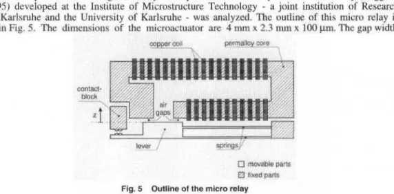
Hcat pipes have found wide acceptance in the thermal managemenl of currcnt spacecraft and in many industrial applications. As conventional two-phase loops, with a common tine for the vapor and liquid nows, hcat pi.pes are ablc to transfer a Jarge amount of thermal energy, at small temperature drop, and without need of a noisy mcchanicaUy driven pump to circulate tbe working fluid. Typical applications of hcat pipes in the range of LOO to 200 W bavc bcen identified to the need to transport waste heat from electronic components of communicalion satcllitcs over radiator areas. Tbe most cornmon heat pipes for space application have been made o f axially grooved aluminum tube. However, due to new rcquirements related to the increased heat loads and reduction in weight, high composite heat pipe configurations (Schlitt, 1995; Dubois et al., 1997), loop beat pipes (Goncharov et al., 1995; Maidanik et ai., 1997) and capillary pumpcd loops (Ku, 1993; Hoang, 1997) are being developed.
Tbe performance of Capillary Pumped Loops (CPL) bave been satisfactory in most ground tests in order to attend the heat transport capability or temperature control as rcquired for space applications. Up to date, several ground tests and also flight tests have been already carried out using different types of capillary pumps. Most capillary pumps bave been built using tubular porous material as the capiUary structure. Porous material currently used in thc capillary pumps are made of bigh density polyethylene or sintered nickel powder. Porous material has the advantage to produce bigber capillary pumping pressure, when compared with axially or circumferentially grooved surfaces. However, some opcrational problems related to the startup and to the repriming ability in case of dryout must still to be cffectivcly solved. Also, porous material is more sensitive to non-condensable gases or to vapor bubbles formation inside of its structure.
Circumfcrcntially grooved heat pipes are also proposed as capillary pumps to be used in two-phase heat transfer loops. Theoretical and experimental results are presenteei here for capillary pumps made of aluminum tubes assembled as the evaporator plate mounted in a two-phase heat transfcr loop. Tbe capillary structure consists of circumferential grooves with slightly different geometry. Tbe corresponding capillary pumping pressure was calculated in the range of 1.3 kPa to 2.0 kPa. First resulls regarding ground tests were reported (Bazzo et al., 1997). As an extension of this work, additional information regarding the tests, a mathematical model and theoretical results are now presented. The experimental results have dcmonstrated its ability to transfer heat fluxes up to 1.7
W/cm2, for an effective inlemal heat transfer surface of tb.e capiUary pump cqual to 0.0166 m2, using
Freon 11 as the working fluid. Success in startup and success in repriming a capillary pump in case of
dryout have been observed. The corresponding values for ammonia was found to be up to ll W/cm2•
18 J . of lhe Braz. Soe. Mechanlcal Sciences ·V oi. 21, March 1999
Despite the low capillary pumpiog pressure, a ci rcumferentially grooved capiiJary pump is a rcliable candidate to be used in smaJ I CPLs, or in those cases whcre the prcssure drops through the vapor and li quid lines are not high enough to lead Lhe systcm to lhe dryout condition.
The Capillary Pump Design
Thc capillary pump consist.s of a 19 mm O .D. aluminum tube with fine circumfercntial grooves machined oo its inncr ~ urfac e. An insert is used to separatc the inlet liquid channel from two outlet vapor channcls. Thc interna! structure of the capillary pump is schematically shown in Fig. 1. 1-leat is applicd, along the vapor scction, ont() the outcr surfacc of lhe capillary pump. The circumferential grooves create Lhe requircd surface lension forces to move thc working fluid from lhe liquid tine, througb lhe groovcd surface , from wherc the hcat is removed by phase chaoging. The actíve length is considered to be equ al to the leogth of the inseri. The internai surface is equal to 2. rr. r1• L= 0 .025 rn2,
where r;= 7.93 mm is lhe internai radius and L = 500 mm is lhe activc Jength of the lu bc. Dueto thc positioo of the insert ~ the effective interna] heat transfer surface of lhe capillary pump is considered to be equaJ to 0.0166 m· (213 of thc total value). T he gcometrical charactcrislics o f thc capillary pump are also schcmatically showo in Fig. 2.
Vapor
channel
Groove
Inseri
Fig. 1 The internai conflguration oi the capillary pump.
R,
Fig. 2 Cross-sectlon of lhe grooved wall.
Groovcs
1
n
tl
\\
p
\11
T st
E. Bazzo et ai.: Theoretical and Experimental Study of a CPL Using ... 19
According to lhe scheme of Fig. 2, w il> lhe groove widlh,
o
is lhe groove depth, 2 ~ is the groovcopening angle. a ís the groove pitch, r, is lhe internai radius of the tube, R1 is lhe smaller meniscus
radius and
e
ilo the conLact anglc. Thc second meniscos R2 is relatively large and its intluencc isneglected in this study (R1 > r1 >> R1 ). To mcasurc thc parameters o f the capillary strucLure, severa!
samples were preparcd in lhe laboratory, cuning lhe capillary pumps afler lhe tcsts.
A microphotograph rclated to one sample is shown in Fíg. 3, where one sees in cross-section lhe
aluminum tube. lt was found thaL Lhe groove structure of lhe capillary pump is not uniform. According
to the microphoLograph analysis o f I O samples from 5 differcnt capillary pumps, lhe following
parameters were measured a:, avcragc valucs:
• IV= 33.0 ± 6.7 J.lffi
• o= 309.7
±
59.2 ~ • a=214.7±9.7~-.tm•
~=
0.57 ± 0.4 degrceFlg. 3 Mlcrophotograph of the grooved wall.
Theoretical Analysis
A computer program was devcloped to observe the capillary pump behavior and to estimate the
maximum hcat transport capability o f the CPL. A nonlinear equation system was derived accounting for
the geomctrical cbaracteristics of the capillary pump. The maximum heal inpul is found when
(I)
where p ,.,. is the maximum capillary pumping pressure, ~ ce is the pressure drop inside the capill ary
pump and .1p1"''" is the pressure drop along the loop. The maxtmum capillary pumping prcssurc is
2a
Pcm=-r,.
(2)
where ais the surface tension o f Lhe workin g Ouid and rc is the effcctive capillary radius of thc groove.
The pbysical meaning and the correspondi ng values for rc of some of the more common wicking
20 J . of the Braz. Soe. Mechanlcal Sclences- V oi. 21. March 1999
2 COS {J ( IV 10 {J )
r,.= --ucan
1-sin{J 2 (3)
Equalions (2) and (3) should bc uscd i f the circumferentiaJ grooves are the only connection between
thc liquid channel and vapor channcl. That means. therc is no gaps at the interface along the insert and
the groovcd wall. Existing gaps are strongly a.ssociated to the capillary action o f lhe capillary pump. In
reality, an cffective capillary pumping pres~ure related to thc gaps. so called Prms• must bc also
calcul ate. or even mcasured in lhe laboratory. The larger the gaps, thc smallcr
p,.,,
8• lt is expected thatthe system works only while P rmR > t1p'"''l"
Thc term óph"'l' is easily calculatcd applying existing correlations available in thc literatu re of nuid mcchanics. On lhe other hand, to calculate óp<P• one should consider lhe changes of the mass flow rale,
m. liquid velocity, v, liquid cross scction, A, meniscus contact angle, 9, meniscus radius, R1 and lhe
meniscus position from tbe inner surfacc of thc tube, y, along a groove lcngth of the capiUary pump (scc
Fig. 4 ). The pressure drop along the liquid cbannel and vapor channcls is relatively small and can bc ncglecled. The pressurc drop along one singlc groove of the capillary pump is calculated taking into account the gcometricaJ characteristics of the capillary structure and thc momentum equation.
(4)
subjcctcd to the foJJowing boundary condition
(5)
where p, is assumed to be equal to thc saturation pressure as a function of tbe loop opcration
temperature. sct through the reservoir. ln Figure 4, p , is the vapor pressure inside the capillary pump
and p,(ljl) is the liquid pressurc along the groove as a function of the angle VI (see also Fig. 5).
Conccrning the right hand sidc of Eq. 4, the tirst tcrm represents the graviry cffcct, the second term rcprcscnts lhe viscous forces, and the third term rcpresents the inertial cffccts. The third term is rclativcly small and can bc neglected.
X
Liquid: P. (
I
r.
f
Flg. 4 Cross-sectlon of one half groove and its geometrlcal characteristics.
E. Bazzo et ai.: Theoretical and Experimental Study of a CPL Using ...
Aluminum tu
Liquid
channcl
Circumfcrcntial groovc
I nsert
Flg. 5 Cross-section of lhe caplllary pump.
21
The problcm is easily solvcd dividing the groove in n cqual elements (i = 1,2, ... ,n), making
!Jp,1, = L/Jp; so that ali these variables can be considered constant along every element, withoul
significant effecl.\i on the evaluation o f the pressure drop. Thus, neglecting thc inerlial effects, onc find ~:
where
- 1C V·=v·( --111 . )
I I 2 T' I
r
it/tPn
=c os
VI dljlI!' i
A;=( Ô-y; ){R li cos( {3+8;
~
tan{J ]-RiJ(; {3-8; >-fsin2( {3+8; )f(6)
(7)
(8)
(9)
( lO)
(11)
22 J . oi lhe Braz. Soe. Mechanical Sciences • Vol. 21. March 1999
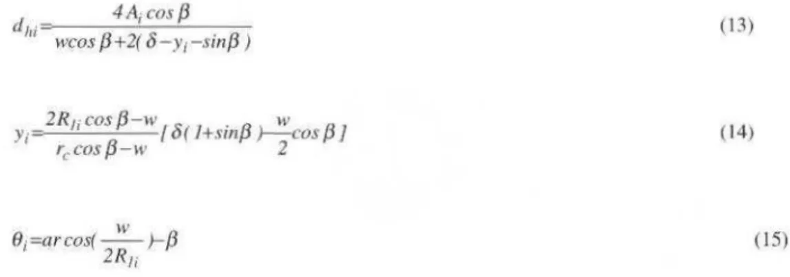
4A;cos {J
dh;=-- - -..:.,____:. _ _ _
WCOS {3+2(
8-y
1-si11{3) ( 13)2Rrcos {3 -w w
Y; ' {J /8( l+sin/3 )--:-cos /31
rccos -w 2 (14)
w
9; =ar c os(-- )-{J
2Rii (15)
where Q, is the total heat input, p1 is thc liquid density, g is Lhe gravitatiooal acceleraLion,
fi
is thefri cLion facLOr of thc ith element. dh, is thc hydraulic diametcr of lhe ith element and
v, is
Lhe liquidvelocity of thc ith c1ement. Addiúooal information about lhe mathematical modc1 de~cribed bere werc
rcportcd for Buzo ( 1996). At such conditions. for a desired heaL input applied onto the capillary pump.
assuming the above boundary condition. lhe problem is solved itcratively, step by stcp. for every clement along the groovc.
Despite the eviden t non-uni formi ty of lhe grooves, in tJ1 is work Lhe geometrical vulues obtained from the microphotograph analysis are used to estimate the maximum heat input capabi lity and to determine the characteristic curve of lhe capillary pump. Freon 11 is assumed to be the working fluid at an operation tempcrature equal to 300 K. The characterisúc curve of lhe capillary pump is plotted in Fig. 6. The in nuence of lhe groove width and the ioner radiu s is shown in Figs. 7 and 8.
12r---~~-~---T====~~
1.0
.f 0.8 .
i 0,6
~
... o.•
...
0.2
Puwer input. W
Fig. 6 Characterlstl c c urves for the c aplllary pump. Comparison wllh pressure fosses along the loop.
The pressure tosse~ concerning two different pipes for lhe CPL are also plotted in Fig. 6, for a
lenglh of 10m of liquid and vapor tines. Curve 1 is plotted taking into account obtained results for O. D. 20 mm. Curve 2 is plotted taking into account obtained res uhs for O. D. 10 mm. The values found
for Curve l are equivalcnt to lhe pressure lo s~e~ found for lhe CPL set-up showo in Fig. 9. In case of
curve I, and aceording to the characteristic curve shown in Fig. 6, it is expected to ftnd a power input of
approximately 250 W a~, lhe maximum hcat inputto the transported by lhe CPL. In case o f curve 2, this
value falls to 170 W.
Despitc thcir low capillary pumping pressu re, circumfcrentially grooved capi llary pumps could be also tlpplied in large two-phasc heat transfer loops. Onc could select liqui.d !ines and vapor tines of largcr diameters, oncc tbc increase in weight of the 1oop is not so high. So, Lhe pressurc losses to be
overcome can bc as ~ma ll as desirable, or poss ible. In fact, there is no reason to dismiss
c ircumfereotially grooved capillary pumps as possible candidates in two-phase heat transport loops for
space applicaúons. However. special care about lheir manufacture must be takeo. The manufactnre of a
circumfcrcotially grooved capillary pump is not so easy as the manufacturc of tubular porous material capillary pumps. Spccial tools are required to machioe fi ne circumfcrcntial grooves along the inner
surface of small tubcs. Also, special care must bc taken in fi tting thc insert inside lhe tube in order to
avoid any damage or any gap atthe in terface with the grooved wa ll.
E. Bazzo et ai.: Theoretical and Experimental Study of a CPL Using ...
.l. ... . ...
~...
I
.. L.
I
L.
I
... !.. ...
I
Freon 11
(300 K)
.i.. . .. ;.
5 10 15 20 25
Inner radius of the tube, mm
30
Flg. 7 Capillary limitas a function of the inner radius of the caplllary pump.
23
The groove width and tbe groove opening angle also have a strong influcncc ovcr the capillary
limitation o f the pump. Thc üúluence of the groove width is shown in Fig. 8 for two diffcrcnt values of
groove opening angles ({J = 0.57" and {3
=
3°). The value () = 0.57n represents the average gwoveopcning angle of the capitlary pumps testcd in the laboratory. The remaining parameters related to
ô,
aand r were kept constant and also equal to the average values found from the microphotograph analysis.
For {3
=
0.57°, one can see a maximum heat input of about 34 W/cm at groove width near to 130IJ.ID.
But it is also shown in Fig. 8 that the maximum capillary pumping pressure decreases steeply for higher values of groovc widths. Therefore, it stands to reason that the best choice does not mean tinding the
point where the heat input is maximum. A small value for lhe groove width is preferable because of its
higher capillary pumping pressure. So, by comparing the two curves, rectangular grooves ({J = 0") look
bel ter than trapezoidal grooves ({J > 0").
9
"'
~=p.s70
~
2
:::1 6 .."'
"'
e
P.
~
3:::l
·a
"'
u
J
Freonll E 30 .... (300 K)
~
]
20~
s
lOª"
u
40 80 120 160 200
Groove width, ).1m
24 J . of lhe Braz. Soe. Mechanical Sclences • Vol. 21, March 1999
Due to i L~ smallcr e ffectívc capillary radius. one should expect bígher capílli>ry pumpíng prcssure
for a trapezoidal groovc than for a reclangular groovc. Howcvcr. for lligh inputs applied to a CPL, trapezoidal grooves are not ablc lo mainlaín the capíllary pumping pressure as rectangular groovcs. In
fact. good performance i~> poss ible only for very small hea1 input applied on1o the evaporator. H was
dcmonstrated that lhe higher thc ~ angle, the hi gher the infiucnce of the loop prcssure drop over the
meniscus radius o f thc !,'l'Oovcs (see Bazzo et al., 1994). So, it ís possíble to transpot1 higher heat inputs
and lo overcome higher pressure losscs with rcctangular groovcs. Anyway, to overcome any additional pressure drop during lhe startup. or even during the normal ope ration of the loop, onc should make the option for capillary pumps with narrow grooves.
Experimental Set-up
Ali the lests wcre carried out al IKE (lnslitut für Kernencrgetik und Energícsystemc) of lhe Univcrsity of Stuttgart. Thc se1-up consisted bac;ically of one cvaporator wilh scvcn capillary pumps. one condcnser and one reservoir (see Fig. 9). Ali lhe capillary pumps have similar groove structure. Thc rescrvoir is uscd lo conlrol lhe liquid inventory in the loop. ll was designcd to contain enough liquid to cnsure a good performance of lhe loop. A nearly blockcd condcn:,cr section must occur whcn a minimum hcal input is applicd to lhe cvaporator al lhe mi.nimum condenser sink temperature. On lhe
other hand, lhe condcn:.er musl be fully actíve whcn a maximum heat input is applied to lhe evaporalor
at lhe maximum condcnser tcmperaturc.
TIS
Detaii: Capillary pump
(Evaporawr)
Fig. 9 Schematlc of the CPL set-up.
The CPL was instrumented wilh 27 thermocouples, two differential pressure sensors (DPS). one absolute prcssure sensor (APS), one digital voltmcler, onc digital amperemctcr and onc water-cooling t1owmeter. Two cryostals and one DC-power supply werc used opcrale thc CPL. A firsl cryoslat was
uscd to contro l the tcmperaturc o f the rc~>ervoir. The second cryostal was uscd lo remove heat from the
~
(
f
c
'
I..
i:
t tJ
J:
p
te
a
Jj
d
...